EP1203684A2 - Dispositif d'admission d'air pour véhicule - Google Patents
Dispositif d'admission d'air pour véhicule Download PDFInfo
- Publication number
- EP1203684A2 EP1203684A2 EP01850188A EP01850188A EP1203684A2 EP 1203684 A2 EP1203684 A2 EP 1203684A2 EP 01850188 A EP01850188 A EP 01850188A EP 01850188 A EP01850188 A EP 01850188A EP 1203684 A2 EP1203684 A2 EP 1203684A2
- Authority
- EP
- European Patent Office
- Prior art keywords
- air
- screen
- air intake
- intake system
- flow path
- Prior art date
- Legal status (The legal status is an assumption and is not a legal conclusion. Google has not performed a legal analysis and makes no representation as to the accuracy of the status listed.)
- Withdrawn
Links
- 230000007246 mechanism Effects 0.000 claims description 6
- 230000005484 gravity Effects 0.000 claims description 2
- 238000000034 method Methods 0.000 claims 2
- 239000000463 material Substances 0.000 description 4
- 238000004026 adhesive bonding Methods 0.000 description 2
- 238000004140 cleaning Methods 0.000 description 2
- 238000002485 combustion reaction Methods 0.000 description 2
- 239000002184 metal Substances 0.000 description 2
- 239000004033 plastic Substances 0.000 description 2
- 230000000630 rising effect Effects 0.000 description 2
- 238000003466 welding Methods 0.000 description 2
- 238000009825 accumulation Methods 0.000 description 1
- 239000000356 contaminant Substances 0.000 description 1
- 230000007812 deficiency Effects 0.000 description 1
- 230000000994 depressogenic effect Effects 0.000 description 1
- 239000000428 dust Substances 0.000 description 1
- 239000011152 fibreglass Substances 0.000 description 1
- 230000007257 malfunction Effects 0.000 description 1
- 238000004519 manufacturing process Methods 0.000 description 1
- 239000000203 mixture Substances 0.000 description 1
- 238000012216 screening Methods 0.000 description 1
- 230000035939 shock Effects 0.000 description 1
- 238000003860 storage Methods 0.000 description 1
Images


Classifications
-
- B—PERFORMING OPERATIONS; TRANSPORTING
- B60—VEHICLES IN GENERAL
- B60K—ARRANGEMENT OR MOUNTING OF PROPULSION UNITS OR OF TRANSMISSIONS IN VEHICLES; ARRANGEMENT OR MOUNTING OF PLURAL DIVERSE PRIME-MOVERS IN VEHICLES; AUXILIARY DRIVES FOR VEHICLES; INSTRUMENTATION OR DASHBOARDS FOR VEHICLES; ARRANGEMENTS IN CONNECTION WITH COOLING, AIR INTAKE, GAS EXHAUST OR FUEL SUPPLY OF PROPULSION UNITS IN VEHICLES
- B60K13/00—Arrangement in connection with combustion air intake or gas exhaust of propulsion units
- B60K13/02—Arrangement in connection with combustion air intake or gas exhaust of propulsion units concerning intake
-
- B—PERFORMING OPERATIONS; TRANSPORTING
- B62—LAND VEHICLES FOR TRAVELLING OTHERWISE THAN ON RAILS
- B62D—MOTOR VEHICLES; TRAILERS
- B62D25/00—Superstructure or monocoque structure sub-units; Parts or details thereof not otherwise provided for
- B62D25/08—Front or rear portions
- B62D25/10—Bonnets or lids, e.g. for trucks, tractors, busses, work vehicles
- B62D25/12—Parts or details thereof
-
- B—PERFORMING OPERATIONS; TRANSPORTING
- B60—VEHICLES IN GENERAL
- B60Y—INDEXING SCHEME RELATING TO ASPECTS CROSS-CUTTING VEHICLE TECHNOLOGY
- B60Y2200/00—Type of vehicle
- B60Y2200/20—Off-Road Vehicles
- B60Y2200/252—Snowmobiles
Definitions
- This invention relates to an air intake system for a vehicle, and more particularly to an air intake system for a vehicle such as a snowmobile that resists drawing in debris, and that is less noisy for a vehicle operator.
- Known motorized vehicles require air intake systems to provide air to an engine, most commonly an internal combustion engine.
- vehicles are equipped with simple "straight-line” air intakes that draw air in an essentially linear path from the outside to the engine. This is unsatisfactory for a variety of reasons.
- a path that permits the flow of air may also permit the flow of debris, such as dust, snow, rain, leaves, etc.
- debris such as dust, snow, rain, leaves, etc.
- engines are typically very sensitive to contaminants, such debris can cause malfunctions or damage if drawn in.
- An embodiment of an air intake system in accordance with the principles of the present invention includes a hood adapted to be connected to a vehicle.
- the hood comprises first and second portions.
- the second portion is engaged with the first portion, and is vertically displaced from the first portion.
- the second portion is essentially a raised or depressed area of the hood.
- the first portion also underlies the second portion.
- the first and second portions cooperate to form at least one intake aperture through the hood.
- the first and second portions may be separate pieces that are fitted and/or secured together.
- the hood may be formed as a single piece, with the first and second portions being integral with one another.
- the second portion is shaped so as to extend horizontally beyond the intake apertures, such that the intake apertures advantageously have zero exposed area in the upper surface of the hood. That is, the intake apertures cannot be seen from above the hood. In this configuration, debris cannot fall directly into the intake apertures from above. This is of particular importance with regard to snow, ice, and other debris. Additionally, the intake apertures are unlikely to become blocked or filled with accumulating debris. This is of importance with regard to storage of the vehicle, when snow can accumulate from above onto the upper surface of the vehicle.
- the air intake system also comprises a screening device, such as a mesh type screen or a filter material, hereinafter referred to as a "screen", engaged with the lower surface of the second portion in such a way that the lower surface and the screen define a cavity therebetween.
- a screening device such as a mesh type screen or a filter material, hereinafter referred to as a "screen”
- the screen defines at least one screen aperture therethrough.
- the air intake system may further comprise a screen mount.
- the screen mount is engaged with the lower surface of the second portion of the hood, and is engaged with the screen at the screen aperture.
- the screen mount defines at least one mount inlet located between the screen and the lower surface of the second portion of the hood, and at least one mount outlet.
- the mount inlet and the mount outlet are in communication with one another such that air may flow therethrough.
- air may flow from the cavity defined between the second portion of the hood and the screen, into the mount inlet, through the screen mount, and out through the mount outlet.
- the hood, screen, and screen mount cooperate to define at least one air path from the intake apertures to the mount outlet.
- the cavity comprises a portion of the air flow path.
- the hood, screen and screen mount are configured so that the air flow path is non-linear.
- the air flow path inclines upwards near the intake apertures, and inclines downwards near the mount outlet, so that air must rise and then fall as it passes through the air flow path.
- Such an air flow path tends to minimize the amount of debris carried from the intake apertures to the mount outlet, and reduces the passage of sound therethrough.
- an air flow path that is configured such that air travels upward through the screen is especially advantageous, since it is particularly effective in preventing debris from passing through the air flow path. Also, when the air flow path has such a configuration, debris that is stopped by the screen falls naturally from the screen, making such an air intake system resistant to the accumulation of debris, and at least partially self-cleaning.
- the intake apertures and screen mount are located far from the operator, so as to further minimize perceived engine noise.
- the intake apertures are located on the opposite side of a windshield from the operator.
- the air intake system may also comprise an air plenum engaged with the screen mount.
- the air plenum serves to baffle the air, further restricting the emission of noise from the engine.
- Figure 1 is a perspective view of an embodiment of an air intake system in accordance with the principles of the present invention, without the second portion.
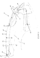
- Figure 2 is a longitudinal cross section of the air intake system shown in Figure 1.
- Figure 3 is a perspective view of an embodiment of the second portion of the hood.
- Figure 4 is a perspective view of an embodiment of an air intake system.
- Figure 5 is another perspective view of an embodiment of an air intake system.
- the present invention comprises an air intake system 10 suitable for use with a vehicle.
- the air intake system 10 is configured so as to be suitable for use with a snowmobile. Details of the engine, steering system, etc. are omitted for clarity. It will be apparent to those knowledgeable in the art that the present invention may also be suitable for use with other vehicles, including but not limited to personal watercraft, etc. Suitable vehicles are well known, and are not described herein in detail.
- the air intake system 10 comprises a hood 20 adapted to be engaged with a vehicle.
- the hood 20 comprises a first portion 21 and a second portion 22.
- the second portion 22 is engaged with the first portion 21, and is vertically displaced from the first portion 21. That is, the second portion 22 is essentially a raised area of the hood 20, while the first portion 21 is that portion of the hood other than the raised second portion 22.
- the first portion 21 extends horizontally across the area over which the second portion 22 extends when in place on the first portion 21.
- first portion 21 and the second portion 22 are separate pieces that are connected together to form the hood 20.
- the first portion 21 of the embodiment is illustrated in Figure 1, and the second portion 22 is illustrated separately in Figure 3.
- a hood 20 formed as a single piece, wherein the first and second portions 21 and 22 are integral with one another, may be equally suitable.
- a hood 20 that is formed as more than two pieces may be equally suitable.
- the underlying part 23 of the first portion 21 over which the second portion 22 extends may be a separate piece from the remainder of the first portion 21.
- hood 20 has a particular streamlined shape for reasons of efficiency and aesthetics, it will be apparent to those knowledgeable in the art that a wide variety of other shapes may be equally suitable.
- the second portion 22 may be removable from the first portion 21.
- the first and second portions 21 and 22 cooperate to define at least one intake aperture 24 through the hood 20.
- the second portion 22 of the hood 20 comprises an upper surface 26 and a lower surface 28.
- the second portion 22 is configured so that it extends horizontally beyond the intake apertures 24, such that the intake apertures 24 have substantially zero exposed horizontal area.
- the intake apertures 24 With the hood 20 oriented for engagement with a vehicle, the intake apertures 24 have substantially zero area of projection on a plane located above the hood 20 and generally parallel to a surface on which the vehicle would rest. With such a configuration, debris cannot fall from directly above the hood 20 into the intake apertures 24. Additionally, debris falling from directly above the hood 20 cannot block or accumulate within the intake apertures 24.
- the embodiment of the hood 20 shown comprises intake apertures 24 in particular shapes.
- some or all of the intake apertures 24 are far from the operator of the vehicle, so as to minimize engine noise as perceived by the operator.
- the intake apertures 24 are defined in a portion of the hood 20 on the opposite side of a windshield 12.
- the windshield 12 is disposed between the intake apertures 24 and an operator. This is particularly advantageous in reducing engine noise as perceived by the operator.
- a variety of shapes, sizes, locations, and numbers of intake apertures may be equally suitable.
- the air intake system 10 further comprises a screen 30.
- the screen 30 allows air to flow therethrough, but prevents debris from passing therethrough and reaching the engine air inlet 14.
- the outer edge 34 of screen 30 is in engagement with the lower surface 28 of the hood 20, such that the lower surface 28 and the screen 30 cooperate to define a cavity therebetween.
- the screen 30 may be removably mounted to the lower surface 28 of the second portion 22.
- the outer edge 34 of the screen 30 may comprise a edge mounting mechanism 35 to enable convenient engagement of the screen 30 with the lower surface 28.
- a variety of edge mounting mechanisms 35 may be suitable for engaging the screen 30 with the lower surface 28.
- a mounting rim or a screen holder may be suitable.
- these mechanisms are exemplary only, and other mechanisms may be equally suitable.
- the screen 30 defines at least one screen aperture 32 therethrough, the screen aperture having an inner edge 36.
- the air intake system 10 may also comprise a screen mount 40 disposed within the screen aperture 32.
- the screen mount 40 may be engaged with at least one of the lower surface 28 and the screen 30.
- the screen mount 40 is engaged with both the screen 30 and the lower surface 28.
- the screen mount 40 may be engaged with a plenum 60.
- the screen mount 40 defines at least one mount inlets 42 between the lower surface 28 and the screen 30 .
- the screen mount also defines at least one mount outlet 44. As illustrated in Figure 2, the mount outlet 44 is below the screen 30. However, the mount outlet 44 could also be above the screen 30, or at the same level as the screen 30.
- the mount inlets 42 and the mount outlet 44 are in communication with one another such that air may flow therethrough.
- the screen mount 40 serves as a durable contact point for the screen 30 and the mount outlet 44.
- the screen 30 may be secured to the screen mount 40 by gluing, welding, etc.
- the screen mount 40 may be generally cylindrical in form, and may be made of plastic, metal, or other suitable material.
- the screen mount 40 may be secured by welding, gluing, etc. or may be part of an integrally formed structure.
- the mount inlets 42 may be in the form of apertures or notches in the upper portion of the wall of the screen mount 40.
- screen mount 40 is exemplary only, and that embodiments of the air intake system 10 without a screen mount 40 may be equally suitable.
- a screen mount 40 is illustrated that is engaged with the hood 20 and the screen 30 and removably engaged with the plenum 60.
- this configuration of outflow mount is exemplary only, and that other configurations of outflow mount, or no outflow mount at all, may be equally suitable.
- the air intake system 10 defines an air flow path 50 therein, extending from the intake apertures 24 to the engine air inlet 14.
- the screen 30 is spaced apart from the lower surface 28, so that the screen 30, the lower surface 28, and the outflow mount 40 cooperate to define a cavity 52.
- the cavity 52 comprises a portion of the air flow path 50.
- the air flow path 50 extends from the intake apertures 24, through the screen 30, and through the cavity 52 to the mount inlets 42, through the screen mount 40, and to the mount outlet 44.
- the outer edge 34 of the screen 30 is in contact with the lower surface 28 of the second portion 22 above the intake apertures 24, and the inner edge 36 of the screen 30 is in contact with the screen mount 40 below the mount inlets 42 so as to bound the air flow path 50.
- the air entering through the intake apertures 24 thus passes through the screen 30 before it reaches the mount inlets 42.
- an air flow path is exemplary only, and that other configurations may be equally suitable.
- an air flow path would be defined by the screen 30 and lower surface 28, and would extend from the intake apertures 24 to the mount outlet 44.
- the air flow path 50 is shaped such that air traveling therethrough must move in a non-linear fashion. That is, air flowing from the intake apertures 24 to the mount outlet 44 must travel in a curve or around at least one comer. Arrows marked on Figure 2 indicate exemplary directions of air motion within the air flow path 50.
- the air flow path 50 is shaped so that air traveling therethrough must travel upward through the screen 30, rising near the intake apertures 24 and falling near the mount outlet 44. Such a configuration is particularly effective for preventing the movement of debris along with flowing air.
- any debris stopped by the screen 30 will be on the underside of the screen 30. It is thus unlikely that debris will adhere to or accumulate on the screen 30, since gravity tends to remove any debris attached to it. Vibrations and shocks, as from the engine and from the motion of the vehicle, will also tend to loosen any debris.
- the screen 30 is at least partially self-cleaning.
- the screen may be shaped so as to be generally parallel with the lower surface 28 of the second portion 22 of the hood 20 .
- This is advantageous, in that the shape of the hood 20 in the embodiment illustrated yields an air flow path 50 with non-linear air flow while taking up relatively little volume.
- this shape is exemplary only, and that other shapes may be equally suitable.
- the embodiment illustrated comprises an air plenum 60 removably engaged with the mount outlet 44.
- the air plenum 60 is adapted to provide air to an engine, in particular to an internal combustion engine.
- the air plenum 60 serves to further baffle and disrupt the flow of sound from the engine.
- the removable engagement permits the easy engagement and disengagement of the screen mount 40 and the plenum 60, e.g. when opening and closing the hood 20.
- this configuration is exemplary only, and that other configurations of plenum, including but not limited to a plenum that is flexible to accommodate motion of the hood with or without being removably engagable, or no plenum at all, may be equally suitable.
- the plenum 60 comprises at least a portion of the airflow path 50.
- the air intake system 10 may also define a further intake aperture 25 provided in addition to or instead of the intake apertures 24.
- the further intake aperture 25 may be located nearer the operator, for example in front of the windshield, and may have a non-zero exposed area in the upper surface 26 of the hood 20. Air entering through the further intake aperture 25 enters the air flow path 50 as does air entering the intake apertures 24.
- air entering through the further intake aperture 25 also travels upward through the screen 30, rising near the further intake aperture 25 and falling near the mount outlet 44.
- a further intake aperture 25 is illustrated with a particular shape and location. However, it will be apparent to those knowledgeable in the art that a further intake aperture 25 with a different configuration, or no further intake aperture 25 at all, may be equally suitable.
- the air intake system 10 may comprise a variety of generally durable materials. Suitable materials include but are not limited to plastic, metal, and fiberglass.
- the air intake system may also comprise filters, seals, and engagement mechanisms. Such devices are well known, and are not detailed further herein.
Landscapes
- Engineering & Computer Science (AREA)
- Chemical & Material Sciences (AREA)
- Combustion & Propulsion (AREA)
- Transportation (AREA)
- Mechanical Engineering (AREA)
- Cooling, Air Intake And Gas Exhaust, And Fuel Tank Arrangements In Propulsion Units (AREA)
Applications Claiming Priority (2)
| Application Number | Priority Date | Filing Date | Title |
|---|---|---|---|
| US24588600P | 2000-11-03 | 2000-11-03 | |
| US245886P | 2000-11-03 |
Publications (2)
| Publication Number | Publication Date |
|---|---|
| EP1203684A2 true EP1203684A2 (fr) | 2002-05-08 |
| EP1203684A3 EP1203684A3 (fr) | 2004-02-11 |
Family
ID=22928502
Family Applications (1)
| Application Number | Title | Priority Date | Filing Date |
|---|---|---|---|
| EP01850188A Withdrawn EP1203684A3 (fr) | 2000-11-03 | 2001-11-02 | Dispositif d'admission d'air pour véhicule |
Country Status (3)
| Country | Link |
|---|---|
| US (1) | US6968916B2 (fr) |
| EP (1) | EP1203684A3 (fr) |
| CA (1) | CA2361045A1 (fr) |
Families Citing this family (10)
| Publication number | Priority date | Publication date | Assignee | Title |
|---|---|---|---|---|
| US7040437B1 (en) | 2004-01-06 | 2006-05-09 | Polaris Industries Inc. | Engine air intake system |
| US7237635B2 (en) | 2004-07-12 | 2007-07-03 | Honda Motor Co., Ltd. | Automobile over-bulkhead air intake system |
| US8201651B2 (en) * | 2004-07-12 | 2012-06-19 | Honda Motor Co., Ltd. | Automobile over-bulkhead air intake system |
| US7234555B2 (en) * | 2004-07-12 | 2007-06-26 | Honda Motor Co., Ltd. | Secondary path automobile air intake system |
| EP2205479B1 (fr) * | 2007-08-08 | 2016-05-25 | Mahindra & Mahindra Ltd. | Capot à conduite d'air intégrée |
| US8540043B2 (en) | 2010-08-30 | 2013-09-24 | Honda Motor Co., Ltd. | Over bulkhead air intake for reduced snow ingestion |
| US8439143B2 (en) | 2011-02-21 | 2013-05-14 | Honda Motor Co., Ltd. | Over bulkhead air intake system |
| JP6096616B2 (ja) * | 2013-07-24 | 2017-03-15 | ヤンマー株式会社 | トラクター |
| CN107107964A (zh) * | 2014-10-24 | 2017-08-29 | 洋马株式会社 | 拖拉机的机罩 |
| US11427283B2 (en) * | 2019-12-20 | 2022-08-30 | Polaris Industries Inc. | Snowmobile storage compartment, display, antenna, and body trim system |
Family Cites Families (19)
| Publication number | Priority date | Publication date | Assignee | Title |
|---|---|---|---|---|
| US2881860A (en) * | 1955-04-11 | 1959-04-14 | William A Ternes | Air cleaner and silencer |
| US4249626A (en) * | 1977-09-14 | 1981-02-10 | Kawasaki Motors Corp. U.S.A. | Liquid cooling system |
| US4509926A (en) * | 1982-02-25 | 1985-04-09 | Jacobson Clayton J | Super ventilator jet ski engine hood (boat) |
| US4778029A (en) * | 1987-04-29 | 1988-10-18 | General Motors Coporation | Engine air inlet and silencer for motor vehicle |
| JP2863580B2 (ja) * | 1990-01-12 | 1999-03-03 | ヤマハ発動機株式会社 | 小形雪上車の吸気装置 |
| US5129473A (en) * | 1990-12-18 | 1992-07-14 | Yamaha Hatsudoki Kabushiki Kaisha | Fan/radiator combination for snowmobile with liquid cooled engine |
| JP3156085B2 (ja) * | 1991-01-16 | 2001-04-16 | ヤマハ発動機株式会社 | スノーモビルのエンジン吸気装置 |
| JPH04306168A (ja) * | 1991-01-16 | 1992-10-28 | Yamaha Motor Co Ltd | スノーモビルの導風装置 |
| US5195484A (en) * | 1991-10-24 | 1993-03-23 | General Motors Corporation | Air cleaner and snorkel assembly |
| US5199522A (en) * | 1992-05-27 | 1993-04-06 | Ford New Holland, Inc. | Air inlet for vehicle engine |
| US5689953A (en) * | 1995-03-29 | 1997-11-25 | Kubota Corporation | Cooling system for a liquid-cooled engine |
| US5794733A (en) * | 1996-08-16 | 1998-08-18 | Volvo Gm Heavy Truck Corporation | Vehicle air intake and method |
| FR2782480B1 (fr) * | 1998-08-24 | 2000-10-20 | Solvay | Dispositif et procede d'evacuation des calories d'un compartiment |
| JP3983903B2 (ja) * | 1998-09-11 | 2007-09-26 | 本田技研工業株式会社 | 自動2輪車のエアクリーナ構造 |
| US6167862B1 (en) * | 1999-05-12 | 2001-01-02 | Siemens Canada Limited | Air cleaner system |
| US6056075A (en) * | 1999-05-26 | 2000-05-02 | Daimlerchrysler Corporation | Hood with integrated cooling duct |
| JP4252682B2 (ja) * | 1999-09-02 | 2009-04-08 | 本田技研工業株式会社 | 自動二輪車用エンジンの吸気制御装置 |
| US6439328B1 (en) * | 1999-10-21 | 2002-08-27 | Bombardier Inc. | Adjustable air vent for a vehicle |
| US6484835B1 (en) * | 1999-11-24 | 2002-11-26 | Deere & Company | Air cleaner and hood ducting arrangement |
-
2001
- 2001-11-02 EP EP01850188A patent/EP1203684A3/fr not_active Withdrawn
- 2001-11-02 CA CA002361045A patent/CA2361045A1/fr not_active Abandoned
- 2001-11-02 US US10/007,222 patent/US6968916B2/en not_active Expired - Lifetime
Non-Patent Citations (1)
| Title |
|---|
| None |
Also Published As
| Publication number | Publication date |
|---|---|
| US6968916B2 (en) | 2005-11-29 |
| EP1203684A3 (fr) | 2004-02-11 |
| CA2361045A1 (fr) | 2002-05-03 |
| US20020088656A1 (en) | 2002-07-11 |
Similar Documents
| Publication | Publication Date | Title |
|---|---|---|
| US6968916B2 (en) | Air intake system for a vehicle | |
| US8944197B2 (en) | Intake structure for saddle-ride type vehicle | |
| CN105283663B (zh) | 自动二轮车的空气滤清器 | |
| JP2007314165A (ja) | 自動二輪車 | |
| US7712562B2 (en) | Intake structure of vehicle | |
| CA2807024C (fr) | Structure de systeme d'admission d'air destinee a un vehicule de type a conduite sur selle | |
| US20200215901A1 (en) | Hood air scoop | |
| US8518161B2 (en) | Hood air scoop | |
| US20080242213A1 (en) | Cover for a separating area of an air intake duct of an internal combustion engine | |
| CN101012788B (zh) | 空气滤清器 | |
| JPH0976973A (ja) | 自動二輪車の吸気装置 | |
| CN101987641B (zh) | 小型摩托车型车辆 | |
| JPH06219366A (ja) | スクータ型車両の吸気装置 | |
| JP2004237779A (ja) | 作業車のボンネット | |
| JP4396353B2 (ja) | 冷却空気導入装置 | |
| JP4673168B2 (ja) | 車両用吸気装置 | |
| JPS6230555Y2 (fr) | ||
| JPH08144876A (ja) | 車両用エンジンのエアフィルタ取付構造 | |
| JPH0631060B2 (ja) | エアクリーナ装置 | |
| JP2022144027A (ja) | エンジン用吸気ダクト | |
| JPH03200492A (ja) | 自動二輪車の風防板 | |
| JP4424666B2 (ja) | 車両用内燃機関における吸気用ダクト装置 | |
| JPH08158962A (ja) | ダクトのチャンネルユニット構造 | |
| JPH035512Y2 (fr) | ||
| JPS6024927Y2 (ja) | エア・クリ−ナに使用される集塵ボックス |
Legal Events
| Date | Code | Title | Description |
|---|---|---|---|
| PUAI | Public reference made under article 153(3) epc to a published international application that has entered the european phase |
Free format text: ORIGINAL CODE: 0009012 |
|
| AK | Designated contracting states |
Kind code of ref document: A2 Designated state(s): AT BE CH CY DE DK ES FI FR GB GR IE IT LI LU MC NL PT SE TR |
|
| AX | Request for extension of the european patent |
Free format text: AL;LT;LV;MK;RO;SI |
|
| RAP1 | Party data changed (applicant data changed or rights of an application transferred) |
Owner name: ARCTIC CAT INC. |
|
| RIN1 | Information on inventor provided before grant (corrected) |
Inventor name: BERGMAN, RON |
|
| RIN1 | Information on inventor provided before grant (corrected) |
Inventor name: BERGMAN, RON |
|
| PUAL | Search report despatched |
Free format text: ORIGINAL CODE: 0009013 |
|
| AK | Designated contracting states |
Kind code of ref document: A3 Designated state(s): AT BE CH CY DE DK ES FI FR GB GR IE IT LI LU MC NL PT SE TR |
|
| AX | Request for extension of the european patent |
Extension state: AL LT LV MK RO SI |
|
| 17P | Request for examination filed |
Effective date: 20040719 |
|
| 17Q | First examination report despatched |
Effective date: 20040916 |
|
| AKX | Designation fees paid |
Designated state(s): AT BE CH CY DE DK ES FI FR GB GR IE IT LI LU MC NL PT SE TR |
|
| STAA | Information on the status of an ep patent application or granted ep patent |
Free format text: STATUS: THE APPLICATION IS DEEMED TO BE WITHDRAWN |
|
| 18D | Application deemed to be withdrawn |
Effective date: 20080603 |