EP1203723B1 - Transport- und Lagerungsvorrichtung - Google Patents
Transport- und Lagerungsvorrichtung Download PDFInfo
- Publication number
- EP1203723B1 EP1203723B1 EP01125986A EP01125986A EP1203723B1 EP 1203723 B1 EP1203723 B1 EP 1203723B1 EP 01125986 A EP01125986 A EP 01125986A EP 01125986 A EP01125986 A EP 01125986A EP 1203723 B1 EP1203723 B1 EP 1203723B1
- Authority
- EP
- European Patent Office
- Prior art keywords
- pallet
- wrapping
- lower side
- film
- engagement
- Prior art date
- Legal status (The legal status is an assumption and is not a legal conclusion. Google has not performed a legal analysis and makes no representation as to the accuracy of the status listed.)
- Expired - Lifetime
Links
- 238000003860 storage Methods 0.000 title claims abstract description 11
- 239000004033 plastic Substances 0.000 claims abstract description 30
- 235000013372 meat Nutrition 0.000 claims abstract description 5
- 235000013580 sausages Nutrition 0.000 claims abstract description 5
- 239000000463 material Substances 0.000 claims description 17
- 238000011068 loading method Methods 0.000 claims description 13
- 238000000034 method Methods 0.000 claims description 12
- 239000011888 foil Substances 0.000 claims description 10
- 238000003466 welding Methods 0.000 claims description 8
- 239000000126 substance Substances 0.000 claims description 5
- 238000002407 reforming Methods 0.000 claims 1
- 238000007493 shaping process Methods 0.000 claims 1
- 235000013305 food Nutrition 0.000 abstract description 4
- 239000002985 plastic film Substances 0.000 description 7
- 229920006255 plastic film Polymers 0.000 description 7
- 239000002023 wood Substances 0.000 description 6
- 230000006378 damage Effects 0.000 description 3
- 239000010410 layer Substances 0.000 description 2
- 241000894006 Bacteria Species 0.000 description 1
- 208000027418 Wounds and injury Diseases 0.000 description 1
- 230000000844 anti-bacterial effect Effects 0.000 description 1
- 230000001580 bacterial effect Effects 0.000 description 1
- 230000015572 biosynthetic process Effects 0.000 description 1
- 238000005253 cladding Methods 0.000 description 1
- 238000004140 cleaning Methods 0.000 description 1
- 239000011248 coating agent Substances 0.000 description 1
- 238000000576 coating method Methods 0.000 description 1
- 230000001419 dependent effect Effects 0.000 description 1
- 239000000645 desinfectant Substances 0.000 description 1
- 238000001035 drying Methods 0.000 description 1
- 230000003670 easy-to-clean Effects 0.000 description 1
- 238000001125 extrusion Methods 0.000 description 1
- 230000001771 impaired effect Effects 0.000 description 1
- 238000002347 injection Methods 0.000 description 1
- 239000007924 injection Substances 0.000 description 1
- 208000014674 injury Diseases 0.000 description 1
- 238000004519 manufacturing process Methods 0.000 description 1
- 238000004806 packaging method and process Methods 0.000 description 1
- 239000006223 plastic coating Substances 0.000 description 1
- 238000002360 preparation method Methods 0.000 description 1
- 239000011241 protective layer Substances 0.000 description 1
- 230000002787 reinforcement Effects 0.000 description 1
- 238000007665 sagging Methods 0.000 description 1
- 239000000243 solution Substances 0.000 description 1
- 238000003856 thermoforming Methods 0.000 description 1
- XLYOFNOQVPJJNP-UHFFFAOYSA-N water Substances O XLYOFNOQVPJJNP-UHFFFAOYSA-N 0.000 description 1
Images

Classifications
-
- B—PERFORMING OPERATIONS; TRANSPORTING
- B65—CONVEYING; PACKING; STORING; HANDLING THIN OR FILAMENTARY MATERIAL
- B65D—CONTAINERS FOR STORAGE OR TRANSPORT OF ARTICLES OR MATERIALS, e.g. BAGS, BARRELS, BOTTLES, BOXES, CANS, CARTONS, CRATES, DRUMS, JARS, TANKS, HOPPERS, FORWARDING CONTAINERS; ACCESSORIES, CLOSURES, OR FITTINGS THEREFOR; PACKAGING ELEMENTS; PACKAGES
- B65D19/00—Pallets or like platforms, with or without side walls, for supporting loads to be lifted or lowered
- B65D19/38—Details or accessories
-
- B—PERFORMING OPERATIONS; TRANSPORTING
- B65—CONVEYING; PACKING; STORING; HANDLING THIN OR FILAMENTARY MATERIAL
- B65D—CONTAINERS FOR STORAGE OR TRANSPORT OF ARTICLES OR MATERIALS, e.g. BAGS, BARRELS, BOTTLES, BOXES, CANS, CARTONS, CRATES, DRUMS, JARS, TANKS, HOPPERS, FORWARDING CONTAINERS; ACCESSORIES, CLOSURES, OR FITTINGS THEREFOR; PACKAGING ELEMENTS; PACKAGES
- B65D19/00—Pallets or like platforms, with or without side walls, for supporting loads to be lifted or lowered
- B65D19/0004—Rigid pallets without side walls
- B65D19/0006—Rigid pallets without side walls the load supporting surface being made of a single element
- B65D19/0008—Rigid pallets without side walls the load supporting surface being made of a single element forming a continuous plane contact surface
- B65D19/001—Rigid pallets without side walls the load supporting surface being made of a single element forming a continuous plane contact surface the base surface being made of a single element
- B65D19/0012—Rigid pallets without side walls the load supporting surface being made of a single element forming a continuous plane contact surface the base surface being made of a single element forming a continuous plane contact surface
-
- B—PERFORMING OPERATIONS; TRANSPORTING
- B65—CONVEYING; PACKING; STORING; HANDLING THIN OR FILAMENTARY MATERIAL
- B65D—CONTAINERS FOR STORAGE OR TRANSPORT OF ARTICLES OR MATERIALS, e.g. BAGS, BARRELS, BOTTLES, BOXES, CANS, CARTONS, CRATES, DRUMS, JARS, TANKS, HOPPERS, FORWARDING CONTAINERS; ACCESSORIES, CLOSURES, OR FITTINGS THEREFOR; PACKAGING ELEMENTS; PACKAGES
- B65D2519/00—Pallets or like platforms, with or without side walls, for supporting loads to be lifted or lowered
- B65D2519/00004—Details relating to pallets
- B65D2519/00009—Materials
- B65D2519/00014—Materials for the load supporting surface
- B65D2519/00029—Wood
-
- B—PERFORMING OPERATIONS; TRANSPORTING
- B65—CONVEYING; PACKING; STORING; HANDLING THIN OR FILAMENTARY MATERIAL
- B65D—CONTAINERS FOR STORAGE OR TRANSPORT OF ARTICLES OR MATERIALS, e.g. BAGS, BARRELS, BOTTLES, BOXES, CANS, CARTONS, CRATES, DRUMS, JARS, TANKS, HOPPERS, FORWARDING CONTAINERS; ACCESSORIES, CLOSURES, OR FITTINGS THEREFOR; PACKAGING ELEMENTS; PACKAGES
- B65D2519/00—Pallets or like platforms, with or without side walls, for supporting loads to be lifted or lowered
- B65D2519/00004—Details relating to pallets
- B65D2519/00009—Materials
- B65D2519/00049—Materials for the base surface
- B65D2519/00064—Wood
-
- B—PERFORMING OPERATIONS; TRANSPORTING
- B65—CONVEYING; PACKING; STORING; HANDLING THIN OR FILAMENTARY MATERIAL
- B65D—CONTAINERS FOR STORAGE OR TRANSPORT OF ARTICLES OR MATERIALS, e.g. BAGS, BARRELS, BOTTLES, BOXES, CANS, CARTONS, CRATES, DRUMS, JARS, TANKS, HOPPERS, FORWARDING CONTAINERS; ACCESSORIES, CLOSURES, OR FITTINGS THEREFOR; PACKAGING ELEMENTS; PACKAGES
- B65D2519/00—Pallets or like platforms, with or without side walls, for supporting loads to be lifted or lowered
- B65D2519/00004—Details relating to pallets
- B65D2519/00009—Materials
- B65D2519/00084—Materials for the non-integral separating spacer
- B65D2519/00099—Wood
-
- B—PERFORMING OPERATIONS; TRANSPORTING
- B65—CONVEYING; PACKING; STORING; HANDLING THIN OR FILAMENTARY MATERIAL
- B65D—CONTAINERS FOR STORAGE OR TRANSPORT OF ARTICLES OR MATERIALS, e.g. BAGS, BARRELS, BOTTLES, BOXES, CANS, CARTONS, CRATES, DRUMS, JARS, TANKS, HOPPERS, FORWARDING CONTAINERS; ACCESSORIES, CLOSURES, OR FITTINGS THEREFOR; PACKAGING ELEMENTS; PACKAGES
- B65D2519/00—Pallets or like platforms, with or without side walls, for supporting loads to be lifted or lowered
- B65D2519/00004—Details relating to pallets
- B65D2519/00258—Overall construction
- B65D2519/00283—Overall construction of the load supporting surface
- B65D2519/00293—Overall construction of the load supporting surface made of more than one piece
-
- B—PERFORMING OPERATIONS; TRANSPORTING
- B65—CONVEYING; PACKING; STORING; HANDLING THIN OR FILAMENTARY MATERIAL
- B65D—CONTAINERS FOR STORAGE OR TRANSPORT OF ARTICLES OR MATERIALS, e.g. BAGS, BARRELS, BOTTLES, BOXES, CANS, CARTONS, CRATES, DRUMS, JARS, TANKS, HOPPERS, FORWARDING CONTAINERS; ACCESSORIES, CLOSURES, OR FITTINGS THEREFOR; PACKAGING ELEMENTS; PACKAGES
- B65D2519/00—Pallets or like platforms, with or without side walls, for supporting loads to be lifted or lowered
- B65D2519/00004—Details relating to pallets
- B65D2519/00258—Overall construction
- B65D2519/00283—Overall construction of the load supporting surface
- B65D2519/00298—Overall construction of the load supporting surface skeleton type
-
- B—PERFORMING OPERATIONS; TRANSPORTING
- B65—CONVEYING; PACKING; STORING; HANDLING THIN OR FILAMENTARY MATERIAL
- B65D—CONTAINERS FOR STORAGE OR TRANSPORT OF ARTICLES OR MATERIALS, e.g. BAGS, BARRELS, BOTTLES, BOXES, CANS, CARTONS, CRATES, DRUMS, JARS, TANKS, HOPPERS, FORWARDING CONTAINERS; ACCESSORIES, CLOSURES, OR FITTINGS THEREFOR; PACKAGING ELEMENTS; PACKAGES
- B65D2519/00—Pallets or like platforms, with or without side walls, for supporting loads to be lifted or lowered
- B65D2519/00004—Details relating to pallets
- B65D2519/00258—Overall construction
- B65D2519/00313—Overall construction of the base surface
- B65D2519/00323—Overall construction of the base surface made of more than one piece
-
- B—PERFORMING OPERATIONS; TRANSPORTING
- B65—CONVEYING; PACKING; STORING; HANDLING THIN OR FILAMENTARY MATERIAL
- B65D—CONTAINERS FOR STORAGE OR TRANSPORT OF ARTICLES OR MATERIALS, e.g. BAGS, BARRELS, BOTTLES, BOXES, CANS, CARTONS, CRATES, DRUMS, JARS, TANKS, HOPPERS, FORWARDING CONTAINERS; ACCESSORIES, CLOSURES, OR FITTINGS THEREFOR; PACKAGING ELEMENTS; PACKAGES
- B65D2519/00—Pallets or like platforms, with or without side walls, for supporting loads to be lifted or lowered
- B65D2519/00004—Details relating to pallets
- B65D2519/00258—Overall construction
- B65D2519/00313—Overall construction of the base surface
- B65D2519/00328—Overall construction of the base surface shape of the contact surface of the base
- B65D2519/00333—Overall construction of the base surface shape of the contact surface of the base contact surface having a stringer-like shape
-
- B—PERFORMING OPERATIONS; TRANSPORTING
- B65—CONVEYING; PACKING; STORING; HANDLING THIN OR FILAMENTARY MATERIAL
- B65D—CONTAINERS FOR STORAGE OR TRANSPORT OF ARTICLES OR MATERIALS, e.g. BAGS, BARRELS, BOTTLES, BOXES, CANS, CARTONS, CRATES, DRUMS, JARS, TANKS, HOPPERS, FORWARDING CONTAINERS; ACCESSORIES, CLOSURES, OR FITTINGS THEREFOR; PACKAGING ELEMENTS; PACKAGES
- B65D2519/00—Pallets or like platforms, with or without side walls, for supporting loads to be lifted or lowered
- B65D2519/00004—Details relating to pallets
- B65D2519/00258—Overall construction
- B65D2519/00368—Overall construction of the non-integral separating spacer
- B65D2519/00373—Overall construction of the non-integral separating spacer whereby at least one spacer is made of one piece
-
- B—PERFORMING OPERATIONS; TRANSPORTING
- B65—CONVEYING; PACKING; STORING; HANDLING THIN OR FILAMENTARY MATERIAL
- B65D—CONTAINERS FOR STORAGE OR TRANSPORT OF ARTICLES OR MATERIALS, e.g. BAGS, BARRELS, BOTTLES, BOXES, CANS, CARTONS, CRATES, DRUMS, JARS, TANKS, HOPPERS, FORWARDING CONTAINERS; ACCESSORIES, CLOSURES, OR FITTINGS THEREFOR; PACKAGING ELEMENTS; PACKAGES
- B65D2519/00—Pallets or like platforms, with or without side walls, for supporting loads to be lifted or lowered
- B65D2519/00004—Details relating to pallets
- B65D2519/00547—Connections
- B65D2519/00552—Structures connecting the constitutive elements of the pallet to each other, i.e. load supporting surface, base surface and/or separate spacer
- B65D2519/00557—Structures connecting the constitutive elements of the pallet to each other, i.e. load supporting surface, base surface and/or separate spacer without separate auxiliary elements
- B65D2519/00562—Structures connecting the constitutive elements of the pallet to each other, i.e. load supporting surface, base surface and/or separate spacer without separate auxiliary elements chemical connection, e.g. glued, welded, sealed
-
- B—PERFORMING OPERATIONS; TRANSPORTING
- B65—CONVEYING; PACKING; STORING; HANDLING THIN OR FILAMENTARY MATERIAL
- B65D—CONTAINERS FOR STORAGE OR TRANSPORT OF ARTICLES OR MATERIALS, e.g. BAGS, BARRELS, BOTTLES, BOXES, CANS, CARTONS, CRATES, DRUMS, JARS, TANKS, HOPPERS, FORWARDING CONTAINERS; ACCESSORIES, CLOSURES, OR FITTINGS THEREFOR; PACKAGING ELEMENTS; PACKAGES
- B65D2519/00—Pallets or like platforms, with or without side walls, for supporting loads to be lifted or lowered
- B65D2519/00004—Details relating to pallets
- B65D2519/00547—Connections
- B65D2519/00552—Structures connecting the constitutive elements of the pallet to each other, i.e. load supporting surface, base surface and/or separate spacer
- B65D2519/00572—Structures connecting the constitutive elements of the pallet to each other, i.e. load supporting surface, base surface and/or separate spacer with separate auxiliary element, e.g. screws, nails, bayonets
-
- B—PERFORMING OPERATIONS; TRANSPORTING
- B65—CONVEYING; PACKING; STORING; HANDLING THIN OR FILAMENTARY MATERIAL
- B65D—CONTAINERS FOR STORAGE OR TRANSPORT OF ARTICLES OR MATERIALS, e.g. BAGS, BARRELS, BOTTLES, BOXES, CANS, CARTONS, CRATES, DRUMS, JARS, TANKS, HOPPERS, FORWARDING CONTAINERS; ACCESSORIES, CLOSURES, OR FITTINGS THEREFOR; PACKAGING ELEMENTS; PACKAGES
- B65D2519/00—Pallets or like platforms, with or without side walls, for supporting loads to be lifted or lowered
- B65D2519/00004—Details relating to pallets
- B65D2519/00736—Details
- B65D2519/0086—Protection against environmental hazards, e.g. humidity, bacteria, fire
Definitions
- the invention relates to a transport and storage device for transport and Storage of meat and sausage products and foods subject to EC hygiene guidelines as well as different goods such as chemicals, material goods, equipment etc. with one Wooden pallet with a plank-mounted loading area on crossbars and with along the sides and in the middle below the loading area along running floor planks Feet, the wooden pallet completely with a cover made of plastic film or plastic film-like Material is enclosed close to the pallet.
- Wooden pallets are usually used to transport and store different goods. They are inexpensive and environmentally friendly. The disadvantage is that their surface is not completely smooth. This leads to problems with various goods with hygiene requirements. These must not be stored on wooden pallets. Cleaning problems also arise. The material wood is uneven and therefore easily holds dirt. When it comes into contact with water, it sucks up. This leads to longer drying times. Wood chips can come off, so there is a certain risk of injury. Chips can also penetrate the goods or packaging stored on the pallet and damage them. If chemicals are stored or transported, they can seep into the wood if they accidentally leak. If it is a slippery or even dangerous substance, the entire range must be unloaded and replaced. For these reasons, the use of wooden pallets for certain chemicals is prohibited for safety reasons.
- Plastic pallets cost DM 85 and are relatively expensive compared to wooden pallets at a price of only DM 15.
- the plastic pallets used have to be cleaned with disinfectants. This is also time and cost intensive.
- EP-A-0 727 360 Such a pallet is described in EP-A-0 727 360.
- the preamble of the claim 1 is based on EP-A-0 727 360.
- the object of the invention is to provide a transport and storage device for transporting and storage of different goods of the type mentioned so that the Manufacture of this device is simplified and thereby the transport and storage of meat and sausage products or foods subject to EC hygiene guidelines, more safely and can happen more economically.
- the object of the invention is achieved in that the envelope in the area of a front side of the pallet two small engagement tabs and a large one in the area of a rear side of the pallet Has engagement tab, the distance between the small engagement tabs at least as large as the distance between the tines of a forklift and the diameter of the engagement tabs is not smaller than the cross-sectional diameter of the forks of a forklift and the large engagement tab by two cuts along the outer edges of the stand and one the cuts connecting horizontal section along an underside of the floor plank bounded is.
- the wooden pallet is clad in Plastic foil or plastic-like material, by the before the wooden pallet is inserted large engagement flap is opened and then the bag-like cover over the, for example pallet picked up by a forklift. After stopping the the forklift moves away under the pallet and the tab falls off myself down again. All of this can be done on site at the supplier premises.
- the envelope has then been properly pulled over or put over when the pallet with the front side of the pallet abuts the rear part of the casing and the small engagement tabs lie between the square timbers.
- the palette is completely on the bottom of the Shell.
- the cover fits optimally when the engagement tabs are properly seated and the Cover the pallet without hanging down on it.
- the film is hygienic and washable, and the clad wooden pallet can be reused become. It is portable and can be moved by a forklift without moving the hygiene of the goods or their surroundings is impaired.
- the expensive plastic pallets are saved, and they result in use the plastic pallets no disadvantages.
- the material of the cover i.e. plastic film, is inexpensive and the preparation of the cover can be done easily and quickly. Dressing up the wooden pallet is quick and can also be done on site. The film can be easily cleaned become.
- a plastic film is also suitable for printing commercials, which is an additional Money can mean.
- the large engagement tab has two vertical cuts along the outer edge of the base and a horizontal cut connecting the vertical cuts along an underside of the floor plank, the small engagement tabs running at the level of the front side of the pallet between the feet of the pallet, each engagement tab has two vertical cuts along the inner edges of the base and a horizontal cut connecting the vertical cuts along the underside in the floor plank.
- the design of the small engagement tabs ensures that a conventional forklift can be inserted into the engagement tabs both from the distance of its tines and from their diameter and thus enables the pallet to be transported.
- the engagement tabs are perforated in the casing. The perforation is advantageous if the sleeves are made in stock and delivered to the factories. This means that the tabs cannot be damaged when the sleeves are stored, since they are still integrated in the sleeve. In use, it is no effort to cut the perforation and expose the tabs.
- the envelope can be left around the pallet over several transport processes, so that advertising prints act on the cover and unfold their advertising function. Also can be Apply an advertising print easily and inexpensively, especially with plastic film.
- the device according to the invention can also be used as a can be formed tightly welded pallet in the shell.
- the shell is in the Thermoforming or shrinking process arranged around the wooden pallet. With all procedures the pallet is dressed quickly and easily.
- the envelope is in the form of the outer contour of the pallet arranged, being the contour of the inner base edges and the underside of the crossbar nachformt.
- the pallet is hygienically packed and easy to clean.
- the envelope has when it is welded in is, eight welds, with the welds between the planks of the bed Connect the top and bottom of the case.
- the weld seams allow a special good shape of the film between the feet of the pallet.
- the top and bottom of the Cover made of different film material or differently coated Film material. So it is possible to have different needs for top and bottom take into account, e.g. Slip resistance for the underside thanks to a special non-slip film and bacterial protection for the top by a special antibacterial coating Foil.
- the transport and storage device consists of a plastic cover 1, which is designed so that it has a wooden pallet 2, which for the Transport of goods usually used can be changed.
- the Euro pallet DIN 15146 is mostly used. Basically, any type of Pallet can be clad.
- the disguise can be achieved by covering the bag the film over the pallet and / or by welding the film or by welding the film in the shrinking or deep-drawing process.
- the pallet 2 has a loading area 3 with nine square timbers as feet 4. In These floor planks 13 connecting to them sit lengthwise. The three floor planks 13 run right and left and along the center of the loading area 3 and connect in each case three feet 4 in the longitudinal direction.
- the loading area consists of five planks 18 a, 18 b, 18 c, 18 d, 18 e.
- the feet 4 are firmly connected to them via crossbars 16, 17, namely a crossbar 17 in the middle of the loading area and front and rear outer crossbars 16.
- the feet 4 have outer base edges 11 and inner base edges 15. They stand on floor planks 13.
- the feet of the wooden pallet which are on the front side of the pallet 8, labeled 4 a, b, c, see FIG. 1.
- the casing 1 completely surrounds the pallet 2 and close to the contour, the sleeve or the foil the contour of the inner base edges 15 and the underside of the crossbar 16, 17 is formed.
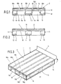
- All outer contours of the pallet are reshaped or shaped so that they in the longitudinal direction of the pallet, tunnel-like areas between those connecting the feet Create floor planks of the wooden pallet, see Figure 4.
- Around the film or Cover to arrange the pallet is suitable for. B. welding the casing 1.
- the shell can be divided into top 6 'and bottom 5'.
- the top of the film can have a special protective layer to ward off bacteria and the underside of the film should be designed to be non-slip. All variants and combinations are possible and depend on the desired properties and the location of the clad pallet.
- the top 6 'of the shell can only be upper Side of the loading area 3, but it can also, if required, up to Reach the floor, i.e. imply the lateral height of the pallet.
- the film or the cover is preferably welded around the pallet. After that in the four spaces between the planks 18 a, b, c, d, e top and bottom the shell welded together. Since the cross bar 17 the shop surface underside interrupts in the middle of the pallet, there are eight weld seams 19.
- the material of the cover 1 should be a stretchable, washable, coatable, tearproof and be printable plastic film or a material with properties similar to Plastic materials or foils.
- the film is like a bag over pulled the pallet. Only the outer contour is recorded.
- the film stretches from the base edges 11 and horizontally connects the floor planks 13. The top and bottom of the film run parallel, see Figures 1, 2 and 3.
- the envelope 1 must be designed so that it surrounds the pallet close to the pallet.
- the distance between the pallet and the case should not be greater than 2 cm.
- the size of the Envelope, d. H. the pallet / envelope distance to be selected is the selected plastic film material dependent. A stiffer film tolerates more distance from the pallet without it begins to hang down from the pallet. If the envelope is shrinked or Deep-drawing process applied, so the process - the casing material has direct Contact with the pallet.
- the envelope 1 surrounding the pallet has two opening areas, namely in the area the front pallet side 8 and in the area of the rear pallet side 9. Die Openings in the film are made through cuts or perforations.
- a flap shape with rounded corner areas is also possible. Here is in Area of intersection: outer base edge 11 / floor plank 13 of the angle less than 45 °. If the tab is subsequently, d. H. with the pallet already clad, into which Cut film, so an accurate cut is not always possible. Thereby however, there are no functional restrictions.
- the opening or engagement area of the casing 1 in the area of the front pallet side 8 consists of two engagement tabs 9 a, 9 b.
- the engagement tab 9 a runs between the feet 4 a and 4 b and the engagement tab 9 b runs between the feet feet 4 b and 4 c.
- the engagement tab 9 a is cut into the shell 1, with two vertical Cuts along the inner edges of the base 15 and one the vertical Horizontal section connecting cuts along the underside of the floor planks 13.
- the small engagement tab 9 b is accordingly along with two vertical cuts the inner base edges 15 and a horizontal cut connecting the vertical cuts produced along the underside of the floor planks 13, see FIG. 1.
- tabs 9 a, 9 b can also be chosen in this way be that they do not cover the entire distance between the feet 4 a, 4 b or 4 b, 4 c, so that the tabs 9 a, 9 b are U-shaped.
- the distance between the small engagement tabs 9 a and 9 b must be chosen at least as large be that the tines of a forklift can be inserted.
- the diameter too the tabs 9 a, 9 b must not be smaller than the diameter cross section of the tines a forklift.
- a tab shape with rounded corners of the tabs 9 a, 9 b is also possible. Here is in the area of the intersection: inner edge of the base 15 / floor plank 13 the angle less than 45 °.
- the engagement tabs 9 a, 9 b are also curtain-like towards the front and towards the rear movable. They fall freely down to the lower edge of the stand 13.
- the engagement tabs 7, 9 a, 9 b can be perforated in the shell.
- the pallet welded into the casing according to FIGS. 4 and 5 can be like a plastic pallet be loaded. Should the loaded or unloaded pallet be transported the forklift drives towards the pallet and guides its tines into the tunnel-like Openings that the film forms and releases.
- the pallet possible, namely welding the film around the pallet or that Cover the pallet with a bag-shaped film. If the pallet is welded in, so the entire range is surrounded by the film. The lower part of the The film only touches the floor planks 13, the underside of the film runs parallel to Top of the film or to the loading area. The pallet so welded into the shell can be loaded like a plastic pallet.
- the forklift moves onto the pallet to, its prongs lead into the spaces between the feet 4 a and 4 b and 4 b and 4 c of pallet 2 and cut the film at this point. It goes without saying this measure is also possible on the rear pallet side 10.
- the pallet 2 can loaded into the plant and stored there.
- the forklift sets the Pallet off and moves away under the pallet, so remain in the area of the tines of the Forklift damage to the film.
- these are immaterial and represent does not constitute a violation of the hygiene regulations.
- the goods may remain on the pallet and stored in this way.
- the casing 1 has then been properly pulled over or put over when the pallet 2 with the front pallet side 8 abuts the rear part of the casing 1 and the engagement tabs 9 a, 9 b between the square timbers 4 a, 4 b and 4 b, 4 c, see Figure 1.
- the pallet can now be put down.
- the large engagement tab 7 completely covers the rear pallet side 10.
- the pallet 2 is completely on the underside 5 of the envelope 1.
- the envelope 1 fits optimally when the engagement tabs are properly seated and the envelope covers the pallet without hanging down on it.
- the pallet is clad in first cut the perforation and open the tabs. Then the palette disguised as described above.
- the hose is stopped and the pallet 2 is moved in with a forklift, and up to the front end of the pallet 8 at the end of the hose or on the hose bottom arrives. Now the engagement tabs can be in the area of the front pallet side 8 by hand 9 a, 9 b can be cut. In the area of the rear pallet side 10 a protrusion is left at pallet height.
- the pallet 2 can be loaded. Should they are moved after the loading process, the forklift can go to the front Drive up pallet side 8 and guide its tines through the engagement tabs 9 a, 9 b, the engagement tabs fold back and clear the way. The palette can now be lifted normally by the forklift.
- the pallet 2 can also be moved from the rear pallet side 10 by forklift or transported.
- the large engagement tab 7 is opened or opened and the forklift tines into the opening. He lifts the Pallet and moves them to the desired location. Once in operation, the clad pallet with goods to be stored.
- plastic films can be used as the cover 1.
- the slide should be printable.
- Plastic sheet-like material can also be used but must be tear-resistant and so stable that it does not grind between wood and goods can be or holes arise.
Landscapes
- Engineering & Computer Science (AREA)
- Mechanical Engineering (AREA)
- Pallets (AREA)
- Packages (AREA)
- Automatic Disk Changers (AREA)
- Refuse Collection And Transfer (AREA)
- Details Of Rigid Or Semi-Rigid Containers (AREA)
Description
Bestehende Hygienerichtlinien für die in der EG zugelassene Betriebe schreiben vor, daß Lebensmittel wie z.B. Fleisch und Wurstwaren nur auf Plastikpaletten in den Betrieben gelagert werden dürfen. Kunststoffpaletten kosten DM 85,-- und sind gegenüber Holzpaletten zu einem Preis von nur DM 15,-- verhältnismäßig teuer.
Gemäß einer bevorzugten Ausgestaltung der Erfindung sind die Eintgriffslaschen in der Hülle perforiert. Die Perforation ist vorteilhaft, wenn die Hüllen auf Vorrat gefertigt und in die Betriebe geliefert werden. So können bei der Lagerung der Hüllen die Laschen nicht beschädigt werden, da sie noch in die Hülle integriert sind. Im Gebrauch ist es kein Aufwand, die Perforation zu durchschneiden und die Laschen freizulegen.
- Figur 1
- : Eine Frontalansicht der vorderen Palettenseite mit übergezogener Hülle im Schnitt,
- Figur 2
- : eine Frontalansicht der hinteren Palettenseite mit übergezogener Hülle im Schnitt,
- Figur 3
- : eine Seitenansicht auf die umkleidete Palette mit aufgeklappter großer Eingriffslasche,
- Figur 4
- : eine Seitenansicht einer weiteren Ausführungsform mit einer der palettenform nachgeformten Hülle,
- Figur 5
- : eine Draufsicht gemäß Ausführungsform von Figur 4.
Die Palette 2 steht vollständig auf der Unterseite 5 der Hülle 1. Die Hülle 1 paßt dann optimal, wenn die Eingriffslaschen ordnungsgemäß sitzen und die Hülle die Palette umkleidet ohne an ihr herunterzuhängen.
Claims (10)
- Transport-und Lagerungsvorrichtung für den Transport und die Lagerung von EG-Hygienerichtlinien unterworfenen Fleisch- und Wurstwaren bzw. Lebensmitteln sowie unterschiedlicher Güter wie Chemikalien, Sachgüter, Gerätschaften etc. mit einer Holzpalette (2) mit einer auf Querriegeln (16,17) lagernden, aus Planken (18a,18b,18c,18d,18e) bestehenden Ladefläche (3) und mit an den Seiten und in der Mitte unterhalb der Ladefläche (3) entlang laufenden Bodenplanken (13) mit Standfüßen (4a,4b,4c,), wobei die Holzpalette (2) vollständig mit einer Hülle (1) aus Plastikfolie bzw. Plastikfolien ähnlichem Material palettennah umschlossen ist, dadurch gekennzeichnet, daß die Hülle (1) im Bereich einer vorderen Palettenseite (8) zwei kleine Eingriffslaschen (9a,9b) und im Bereich einer hinteren Palettenseite (10) eine große Eingriffslasche (7) aufweist, wobei der Abstand zwischen den kleinen Eingriffslaschen (9a) und (9b) mindestens so groß wie der Abstand der Zinken eines Gabelstaplers ist und der Durchmesser der Eingriffslaschen (9a) und (9b) nicht kleiner als der Querschnittsdurchmesser der Zinken eines Gabelstaplers ist und die große Eingriffslasche (7) durch zwei Schnitte entlang äußerer Standfußkanten (11) und einen die Schnitte verbindenden Horizontalschnitt entlang einer Unterseite der Bodenplanke (13) begrenzt ist.
- Vorrichtung nach Anspruch 1, dadurch gekennzeichnet, daß die kleinen Eingriffslaschen (9a,9b) in Höhe der vorderen Palettenseite (8) zwischen den Standfüßen (4a) und (4b) und zwischen den Standfüßen (4b) und (4c) verlaufen, wobei die kleine Eingriffslasche (9a) zwei senkrechte Schnitte entlang innerer Standfußkanten (15) und einen die senkrechten Schnitte verbindenden Horizontalschnitt entlang der Unterseite der Bodenplanke (11) aufweist und die kleine Eingriffslasche (9b) zwei senkrechte Schnitte entlang der inneren Standfußkanten (15) und einen die senkrechten Schnitte verbindenden Horizontalschnitt entlang der Unterseite der Bodenplanke (13) aufweist.
- Vorrichtung nach Anspruch 1 oder 2, dadurch gekennzeichnet, daß die Eingriffslaschen (7,9a,9b) in der Hülle (1) perforiert ausgeführt sind.
- Vorrichtung nach einem der Ansprüche 1 bis 3, dadurch gekennzeichnet, daß die Holzpalette in die Hülle (1) straff eingeschweißt ist.
- Vorrichtung nach Anspruch 4, dadurch gekennzeichnet, daß die Hülle (1) im Tiefziehverfahren und/oder im Schrumpfverfahren um die Holzpalette angeordnet ist.
- Vorrichtung nach einem der Ansprüche 4 oder 5, dadurch gekennzeichnet, daß die Hülle (1) in Form der Außenkontur der Palette (2) angeordnet ist, wobei sie die Kontur der inneren Standfußkanten (15) und die Unterseite der Querriegel (16,17) nachformt bzw. ausformt.
- Vorrichtung nach Anspruch 6, dadurch gekennzeichnet, daß die Hülle (1) acht Schweißnähte aufweist.
- Vorrichtung nach Anspruch 7, dadurch gekennzeichnet, daß zwischen den Planken (18a, 18b, 18c, 18d, 18e) der Ladefläche (3) Schweißnähte (19) Oberseite (6') und Unterseite (5') der Hülle (1) verbinden.
- Vorrichtung nach einem Ansprüche 1 bis 8, dadurch gekennzeichnet, daß Oberseite (9') und Unterseite (5') der Hülle (1) aus unterschiedlichem Folienmaterial bestehen und/oder unterschiedlich beschichtet sind.
- Vorrichtung nach einem der vorhergehenden Ansprüche, dadurch gekennzeichnet, daß die Folie der Hülle (1) bedruckt und/oder beschichtet ist.
Applications Claiming Priority (2)
| Application Number | Priority Date | Filing Date | Title |
|---|---|---|---|
| DE20018815U DE20018815U1 (de) | 2000-11-03 | 2000-11-03 | Transport- und Lagerungsvorrichtung |
| DE20018815U | 2000-11-03 |
Publications (3)
| Publication Number | Publication Date |
|---|---|
| EP1203723A1 EP1203723A1 (de) | 2002-05-08 |
| EP1203723B1 true EP1203723B1 (de) | 2004-09-15 |
| EP1203723B9 EP1203723B9 (de) | 2005-03-02 |
Family
ID=7948447
Family Applications (1)
| Application Number | Title | Priority Date | Filing Date |
|---|---|---|---|
| EP01125986A Expired - Lifetime EP1203723B9 (de) | 2000-11-03 | 2001-10-31 | Transport- und Lagerungsvorrichtung |
Country Status (7)
| Country | Link |
|---|---|
| EP (1) | EP1203723B9 (de) |
| AT (1) | ATE276148T1 (de) |
| DE (4) | DE20018815U1 (de) |
| DK (1) | DK1203723T3 (de) |
| ES (1) | ES2223706T3 (de) |
| PT (1) | PT1203723E (de) |
| TR (1) | TR200402615T4 (de) |
Families Citing this family (6)
| Publication number | Priority date | Publication date | Assignee | Title |
|---|---|---|---|---|
| DE20018815U1 (de) * | 2000-11-03 | 2001-03-15 | Kirschsieper, Rolf, 45886 Gelsenkirchen | Transport- und Lagerungsvorrichtung |
| NO20042931L (no) * | 2003-11-07 | 2005-05-09 | Niels Graae | Overtrukket/impregnert trepaller/treverk til anvendelse i hygieniske folsomme produktioner |
| GB2417720A (en) * | 2004-09-07 | 2006-03-08 | David Hoy | Chock or cradle apparatus for supporting goods |
| FI126663B (fi) * | 2006-02-10 | 2017-03-31 | Metsä Board Oyj | Menetelmä suojakalvon kiinnittämiseksi kuormalavaan, kuormalava ja pakkaus |
| CN110733725B (zh) * | 2019-07-31 | 2021-05-14 | 上海新意达塑料托盘有限公司 | 一种局部焊接工艺及应用该工艺的塑料托盘 |
| US11198537B1 (en) * | 2020-05-28 | 2021-12-14 | Artistic Composite Pallets Llc | Pallet with printed images |
Citations (2)
| Publication number | Priority date | Publication date | Assignee | Title |
|---|---|---|---|---|
| EP0137443A2 (de) * | 1983-10-07 | 1985-04-17 | Hans Lingl Anlagenbau und Verfahrenstechnik GmbH & Co. KG | Vorrichtung zum Aufschrumpfen einer Folienhülle auf ein Paket |
| US4616471A (en) * | 1983-08-03 | 1986-10-14 | Msk-Verpackungs-Systeme Gesellschaft Mit Beschrankter Haftung | Method of packaging a pallet-supported stack of goods |
Family Cites Families (6)
| Publication number | Priority date | Publication date | Assignee | Title |
|---|---|---|---|---|
| FR2612153B1 (fr) * | 1987-03-11 | 1989-10-20 | Anisa Sa | Palette destinee au transport et au stockage de pieces ou de recipients, et son procede de fabrication |
| US5123359A (en) * | 1990-12-03 | 1992-06-23 | T.H.E.M. Of New York, Inc. | Heavy duty pallet and method of making same |
| DE19505241A1 (de) * | 1995-02-16 | 1996-08-22 | Zuckerverbund Nord Ag | Transportpalette aus Kunststoff mit Holzeinlage sowie Herstellungsverfahren dafür |
| BE1012662A3 (nl) * | 1999-05-04 | 2001-02-06 | Hemeldonck Emiel Van | Palet en werkwijze voor het vervaardigen van zulk palet. |
| DE20018815U1 (de) * | 2000-11-03 | 2001-03-15 | Kirschsieper, Rolf, 45886 Gelsenkirchen | Transport- und Lagerungsvorrichtung |
| DE20113954U1 (de) * | 2001-04-07 | 2001-11-22 | Kirschsieper, Rolf, 45886 Gelsenkirchen | Holzpalette |
-
2000
- 2000-11-03 DE DE20018815U patent/DE20018815U1/de not_active Expired - Lifetime
-
2001
- 2001-08-23 DE DE10141373A patent/DE10141373A1/de not_active Withdrawn
- 2001-10-31 DK DK01125986T patent/DK1203723T3/da active
- 2001-10-31 ES ES01125986T patent/ES2223706T3/es not_active Expired - Lifetime
- 2001-10-31 AT AT01125986T patent/ATE276148T1/de not_active IP Right Cessation
- 2001-10-31 PT PT01125986T patent/PT1203723E/pt unknown
- 2001-10-31 TR TR2004/02615T patent/TR200402615T4/xx unknown
- 2001-10-31 DE DE50103609T patent/DE50103609D1/de not_active Expired - Fee Related
- 2001-10-31 EP EP01125986A patent/EP1203723B9/de not_active Expired - Lifetime
- 2001-11-02 DE DE10153909A patent/DE10153909A1/de not_active Withdrawn
Patent Citations (2)
| Publication number | Priority date | Publication date | Assignee | Title |
|---|---|---|---|---|
| US4616471A (en) * | 1983-08-03 | 1986-10-14 | Msk-Verpackungs-Systeme Gesellschaft Mit Beschrankter Haftung | Method of packaging a pallet-supported stack of goods |
| EP0137443A2 (de) * | 1983-10-07 | 1985-04-17 | Hans Lingl Anlagenbau und Verfahrenstechnik GmbH & Co. KG | Vorrichtung zum Aufschrumpfen einer Folienhülle auf ein Paket |
Also Published As
| Publication number | Publication date |
|---|---|
| DE10141373A1 (de) | 2002-05-08 |
| EP1203723B9 (de) | 2005-03-02 |
| PT1203723E (pt) | 2005-01-31 |
| ATE276148T1 (de) | 2004-10-15 |
| DK1203723T3 (da) | 2005-01-10 |
| ES2223706T3 (es) | 2005-03-01 |
| TR200402615T4 (tr) | 2004-11-22 |
| EP1203723A1 (de) | 2002-05-08 |
| DE20018815U1 (de) | 2001-03-15 |
| DE10153909A1 (de) | 2002-09-26 |
| DE50103609D1 (de) | 2004-10-21 |
Similar Documents
| Publication | Publication Date | Title |
|---|---|---|
| DE10250145B4 (de) | Verfahren und Vorrichtung zum Stapeln von Waren auf einer Palette | |
| DE69934920T2 (de) | Stossfeste Verpackung | |
| EP1203723B1 (de) | Transport- und Lagerungsvorrichtung | |
| EP2036818A1 (de) | Verfahren zum Herstellen einer palettenlosen Verpackungseinheit | |
| EP2618702B1 (de) | Kiste, ständer, system und verfahren zur präsentation von produkten | |
| DE102019200723B4 (de) | Vorrichtung zum Kommissionieren von Ladegut auf Paletten und Verfahren zum Kommissionieren | |
| DE2348082C3 (de) | Flaschenverpackung | |
| DE4042550C2 (de) | Verfahren und Verwendung einer Vorrichtung zum Umhüllen von Stückgut | |
| EP0979778B1 (de) | Palette | |
| DE60313768T2 (de) | Palette und Verfahren zu deren Herstellung | |
| CH558741A (de) | Einwegpalette. | |
| EP0357817B1 (de) | Holzregal mit auf unterschiedlichen Höhen anbringbaren Einlegeböden | |
| DE3841539C2 (de) | Transport- und Lagergestell für flache Gegenstände | |
| DE202020002325U1 (de) | Gitterboden für Warenlagerregale | |
| EP1484278B1 (de) | Einrichtung, Regalbediengerät und Regallager zum Ein- und Auslagern von Paletten | |
| DE9001052U1 (de) | Vorrichtung zum Verpacken von palettiertem Packgut | |
| CH678042A5 (de) | ||
| DE10117616A1 (de) | Holzpalette | |
| EP2130775B1 (de) | Verwendung von Antirutsch-Folie bei Paletten | |
| DE9016862U1 (de) | Transport- und Lagergestell | |
| DE20017806U1 (de) | Transportvorrichtung für ein Zweirad | |
| DE2721482A1 (de) | Verpackungseinheit | |
| DE20019549U1 (de) | Verpackungssystem | |
| CH651258A5 (de) | Transportwagen, insbesondere fuer milchpackungen. | |
| DE8908902U1 (de) | Stapelbare Verpackungseinheit |
Legal Events
| Date | Code | Title | Description |
|---|---|---|---|
| PUAI | Public reference made under article 153(3) epc to a published international application that has entered the european phase |
Free format text: ORIGINAL CODE: 0009012 |
|
| AK | Designated contracting states |
Kind code of ref document: A1 Designated state(s): AT BE CH CY DE DK ES FI FR GB GR IE IT LI LU MC NL PT SE TR |
|
| AX | Request for extension of the european patent |
Free format text: AL;LT;LV;MK;RO;SI |
|
| 17P | Request for examination filed |
Effective date: 20021019 |
|
| AKX | Designation fees paid |
Designated state(s): AT BE CH CY DE DK ES FI FR GB GR IE IT LI LU MC NL PT SE TR |
|
| 17Q | First examination report despatched |
Effective date: 20030818 |
|
| GRAP | Despatch of communication of intention to grant a patent |
Free format text: ORIGINAL CODE: EPIDOSNIGR1 |
|
| GRAS | Grant fee paid |
Free format text: ORIGINAL CODE: EPIDOSNIGR3 |
|
| GRAA | (expected) grant |
Free format text: ORIGINAL CODE: 0009210 |
|
| AK | Designated contracting states |
Kind code of ref document: B1 Designated state(s): AT BE CH CY DE DK ES FI FR GB GR IE IT LI LU MC NL PT SE TR |
|
| PG25 | Lapsed in a contracting state [announced via postgrant information from national office to epo] |
Ref country code: CY Free format text: LAPSE BECAUSE OF FAILURE TO SUBMIT A TRANSLATION OF THE DESCRIPTION OR TO PAY THE FEE WITHIN THE PRESCRIBED TIME-LIMIT Effective date: 20040915 |
|
| REG | Reference to a national code |
Ref country code: GB Ref legal event code: FG4D Free format text: NOT ENGLISH Ref country code: CH Ref legal event code: EP |
|
| REG | Reference to a national code |
Ref country code: IE Ref legal event code: FG4D Free format text: GERMAN |
|
| REF | Corresponds to: |
Ref document number: 50103609 Country of ref document: DE Date of ref document: 20041021 Kind code of ref document: P |
|
| PG25 | Lapsed in a contracting state [announced via postgrant information from national office to epo] |
Ref country code: MC Free format text: LAPSE BECAUSE OF NON-PAYMENT OF DUE FEES Effective date: 20041031 Ref country code: LU Free format text: LAPSE BECAUSE OF NON-PAYMENT OF DUE FEES Effective date: 20041031 |
|
| REG | Reference to a national code |
Ref country code: CH Ref legal event code: NV Representative=s name: IPTO AG |
|
| REG | Reference to a national code |
Ref country code: SE Ref legal event code: TRGR |
|
| REG | Reference to a national code |
Ref country code: GR Ref legal event code: EP Ref document number: 20040404317 Country of ref document: GR |
|
| REG | Reference to a national code |
Ref country code: PT Ref legal event code: SC4A Effective date: 20041207 |
|
| GBT | Gb: translation of ep patent filed (gb section 77(6)(a)/1977) |
Effective date: 20050117 |
|
| REG | Reference to a national code |
Ref country code: ES Ref legal event code: FG2A Ref document number: 2223706 Country of ref document: ES Kind code of ref document: T3 |
|
| ET | Fr: translation filed | ||
| PLBE | No opposition filed within time limit |
Free format text: ORIGINAL CODE: 0009261 |
|
| STAA | Information on the status of an ep patent application or granted ep patent |
Free format text: STATUS: NO OPPOSITION FILED WITHIN TIME LIMIT |
|
| 26N | No opposition filed |
Effective date: 20050616 |
|
| PGFP | Annual fee paid to national office [announced via postgrant information from national office to epo] |
Ref country code: NL Payment date: 20081031 Year of fee payment: 8 |
|
| PGFP | Annual fee paid to national office [announced via postgrant information from national office to epo] |
Ref country code: CH Payment date: 20081028 Year of fee payment: 8 Ref country code: DE Payment date: 20081208 Year of fee payment: 8 Ref country code: DK Payment date: 20081031 Year of fee payment: 8 Ref country code: IE Payment date: 20081016 Year of fee payment: 8 Ref country code: TR Payment date: 20081030 Year of fee payment: 8 |
|
| PGFP | Annual fee paid to national office [announced via postgrant information from national office to epo] |
Ref country code: AT Payment date: 20081027 Year of fee payment: 8 Ref country code: ES Payment date: 20081017 Year of fee payment: 8 Ref country code: FI Payment date: 20081024 Year of fee payment: 8 Ref country code: PT Payment date: 20081017 Year of fee payment: 8 |
|
| PGFP | Annual fee paid to national office [announced via postgrant information from national office to epo] |
Ref country code: IT Payment date: 20081027 Year of fee payment: 8 Ref country code: BE Payment date: 20081114 Year of fee payment: 8 Ref country code: SE Payment date: 20081029 Year of fee payment: 8 |
|
| PGFP | Annual fee paid to national office [announced via postgrant information from national office to epo] |
Ref country code: FR Payment date: 20081028 Year of fee payment: 8 |
|
| REG | Reference to a national code |
Ref country code: CH Ref legal event code: PFA Owner name: KIRSCHSIEPER, ROLF Free format text: KIRSCHSIEPER, ROLF#LEITHESTRASSE 42 A#45886 GELSENKIRCHEN (DE) -TRANSFER TO- KIRSCHSIEPER, ROLF#LEITHESTRASSE 42 A#45886 GELSENKIRCHEN (DE) |
|
| PGFP | Annual fee paid to national office [announced via postgrant information from national office to epo] |
Ref country code: GB Payment date: 20081029 Year of fee payment: 8 Ref country code: GR Payment date: 20081027 Year of fee payment: 8 |
|
| BERE | Be: lapsed |
Owner name: *KIRSCHSIEPER ROLF Effective date: 20091031 |
|
| REG | Reference to a national code |
Ref country code: PT Ref legal event code: MM4A Free format text: LAPSE DUE TO NON-PAYMENT OF FEES Effective date: 20100430 |
|
| REG | Reference to a national code |
Ref country code: NL Ref legal event code: V1 Effective date: 20100501 |
|
| REG | Reference to a national code |
Ref country code: CH Ref legal event code: PL |
|
| REG | Reference to a national code |
Ref country code: DK Ref legal event code: EBP |
|
| EUG | Se: european patent has lapsed | ||
| REG | Reference to a national code |
Ref country code: IE Ref legal event code: MM4A |
|
| REG | Reference to a national code |
Ref country code: FR Ref legal event code: ST Effective date: 20100630 |
|
| PG25 | Lapsed in a contracting state [announced via postgrant information from national office to epo] |
Ref country code: PT Free format text: LAPSE BECAUSE OF NON-PAYMENT OF DUE FEES Effective date: 20100430 Ref country code: FR Free format text: LAPSE BECAUSE OF NON-PAYMENT OF DUE FEES Effective date: 20091102 Ref country code: DE Free format text: LAPSE BECAUSE OF NON-PAYMENT OF DUE FEES Effective date: 20100501 Ref country code: NL Free format text: LAPSE BECAUSE OF NON-PAYMENT OF DUE FEES Effective date: 20100501 |
|
| PG25 | Lapsed in a contracting state [announced via postgrant information from national office to epo] |
Ref country code: AT Free format text: LAPSE BECAUSE OF NON-PAYMENT OF DUE FEES Effective date: 20091031 Ref country code: FI Free format text: LAPSE BECAUSE OF NON-PAYMENT OF DUE FEES Effective date: 20091031 |
|
| PG25 | Lapsed in a contracting state [announced via postgrant information from national office to epo] |
Ref country code: LI Free format text: LAPSE BECAUSE OF NON-PAYMENT OF DUE FEES Effective date: 20091031 Ref country code: IE Free format text: LAPSE BECAUSE OF NON-PAYMENT OF DUE FEES Effective date: 20091031 Ref country code: GR Free format text: LAPSE BECAUSE OF NON-PAYMENT OF DUE FEES Effective date: 20100504 Ref country code: CH Free format text: LAPSE BECAUSE OF NON-PAYMENT OF DUE FEES Effective date: 20091031 Ref country code: BE Free format text: LAPSE BECAUSE OF NON-PAYMENT OF DUE FEES Effective date: 20091031 |
|
| PG25 | Lapsed in a contracting state [announced via postgrant information from national office to epo] |
Ref country code: GB Free format text: LAPSE BECAUSE OF NON-PAYMENT OF DUE FEES Effective date: 20091031 |
|
| PG25 | Lapsed in a contracting state [announced via postgrant information from national office to epo] |
Ref country code: DK Free format text: LAPSE BECAUSE OF NON-PAYMENT OF DUE FEES Effective date: 20091031 |
|
| REG | Reference to a national code |
Ref country code: ES Ref legal event code: FD2A Effective date: 20110301 |
|
| PG25 | Lapsed in a contracting state [announced via postgrant information from national office to epo] |
Ref country code: IT Free format text: LAPSE BECAUSE OF NON-PAYMENT OF DUE FEES Effective date: 20091031 |
|
| PG25 | Lapsed in a contracting state [announced via postgrant information from national office to epo] |
Ref country code: SE Free format text: LAPSE BECAUSE OF NON-PAYMENT OF DUE FEES Effective date: 20091101 |
|
| PG25 | Lapsed in a contracting state [announced via postgrant information from national office to epo] |
Ref country code: ES Free format text: LAPSE BECAUSE OF NON-PAYMENT OF DUE FEES Effective date: 20110228 |
|
| PG25 | Lapsed in a contracting state [announced via postgrant information from national office to epo] |
Ref country code: ES Free format text: LAPSE BECAUSE OF NON-PAYMENT OF DUE FEES Effective date: 20081101 |
|
| PG25 | Lapsed in a contracting state [announced via postgrant information from national office to epo] |
Ref country code: TR Free format text: LAPSE BECAUSE OF NON-PAYMENT OF DUE FEES Effective date: 20091031 |