EP1203853A2 - Elément de fixation et méthode pour son montage - Google Patents
Elément de fixation et méthode pour son montage Download PDFInfo
- Publication number
- EP1203853A2 EP1203853A2 EP01122105A EP01122105A EP1203853A2 EP 1203853 A2 EP1203853 A2 EP 1203853A2 EP 01122105 A EP01122105 A EP 01122105A EP 01122105 A EP01122105 A EP 01122105A EP 1203853 A2 EP1203853 A2 EP 1203853A2
- Authority
- EP
- European Patent Office
- Prior art keywords
- screw
- strip
- holder
- strip holder
- fastening element
- Prior art date
- Legal status (The legal status is an assumption and is not a legal conclusion. Google has not performed a legal analysis and makes no representation as to the accuracy of the status listed.)
- Withdrawn
Links
- 238000000034 method Methods 0.000 title claims description 5
- 238000009434 installation Methods 0.000 title description 3
- 239000002023 wood Substances 0.000 claims description 8
- 229910000831 Steel Inorganic materials 0.000 claims description 4
- 239000010959 steel Substances 0.000 claims description 4
- 230000015572 biosynthetic process Effects 0.000 claims description 2
- 230000003287 optical effect Effects 0.000 claims description 2
- 239000000969 carrier Substances 0.000 claims 1
- 239000004033 plastic Substances 0.000 description 5
- 229920003023 plastic Polymers 0.000 description 5
- 208000000260 Warts Diseases 0.000 description 4
- 230000008901 benefit Effects 0.000 description 4
- 201000010153 skin papilloma Diseases 0.000 description 4
- 238000009413 insulation Methods 0.000 description 3
- 230000004888 barrier function Effects 0.000 description 2
- 230000008439 repair process Effects 0.000 description 2
- 229920002430 Fibre-reinforced plastic Polymers 0.000 description 1
- 238000004026 adhesive bonding Methods 0.000 description 1
- 230000009286 beneficial effect Effects 0.000 description 1
- 238000005253 cladding Methods 0.000 description 1
- 230000000295 complement effect Effects 0.000 description 1
- 239000002131 composite material Substances 0.000 description 1
- 239000011151 fibre-reinforced plastic Substances 0.000 description 1
- 238000005755 formation reaction Methods 0.000 description 1
- 235000021189 garnishes Nutrition 0.000 description 1
- 230000001771 impaired effect Effects 0.000 description 1
- 238000004519 manufacturing process Methods 0.000 description 1
- 238000005259 measurement Methods 0.000 description 1
- 239000002184 metal Substances 0.000 description 1
- 229910001092 metal group alloy Inorganic materials 0.000 description 1
- 238000000465 moulding Methods 0.000 description 1
- 239000004575 stone Substances 0.000 description 1
- 230000000007 visual effect Effects 0.000 description 1
Images

Classifications
-
- E—FIXED CONSTRUCTIONS
- E04—BUILDING
- E04F—FINISHING WORK ON BUILDINGS, e.g. STAIRS, FLOORS
- E04F13/00—Coverings or linings, e.g. for walls or ceilings
- E04F13/07—Coverings or linings, e.g. for walls or ceilings composed of covering or lining elements; Sub-structures therefor; Fastening means therefor
- E04F13/08—Coverings or linings, e.g. for walls or ceilings composed of covering or lining elements; Sub-structures therefor; Fastening means therefor composed of a plurality of similar covering or lining elements
- E04F13/0801—Separate fastening elements
- E04F13/0803—Separate fastening elements with load-supporting elongated furring elements between wall and covering elements
- E04F13/0805—Separate fastening elements with load-supporting elongated furring elements between wall and covering elements with additional fastening elements between furring elements and the wall
- E04F13/0807—Separate fastening elements with load-supporting elongated furring elements between wall and covering elements with additional fastening elements between furring elements and the wall adjustable perpendicular to the wall
-
- E—FIXED CONSTRUCTIONS
- E04—BUILDING
- E04F—FINISHING WORK ON BUILDINGS, e.g. STAIRS, FLOORS
- E04F13/00—Coverings or linings, e.g. for walls or ceilings
- E04F13/07—Coverings or linings, e.g. for walls or ceilings composed of covering or lining elements; Sub-structures therefor; Fastening means therefor
- E04F13/08—Coverings or linings, e.g. for walls or ceilings composed of covering or lining elements; Sub-structures therefor; Fastening means therefor composed of a plurality of similar covering or lining elements
- E04F13/0801—Separate fastening elements
- E04F13/0803—Separate fastening elements with load-supporting elongated furring elements between wall and covering elements
- E04F13/081—Separate fastening elements with load-supporting elongated furring elements between wall and covering elements with additional fastening elements between furring elements and covering elements
- E04F13/0821—Separate fastening elements with load-supporting elongated furring elements between wall and covering elements with additional fastening elements between furring elements and covering elements the additional fastening elements located in-between two adjacent covering elements
-
- F—MECHANICAL ENGINEERING; LIGHTING; HEATING; WEAPONS; BLASTING
- F16—ENGINEERING ELEMENTS AND UNITS; GENERAL MEASURES FOR PRODUCING AND MAINTAINING EFFECTIVE FUNCTIONING OF MACHINES OR INSTALLATIONS; THERMAL INSULATION IN GENERAL
- F16B—DEVICES FOR FASTENING OR SECURING CONSTRUCTIONAL ELEMENTS OR MACHINE PARTS TOGETHER, e.g. NAILS, BOLTS, CIRCLIPS, CLAMPS, CLIPS OR WEDGES; JOINTS OR JOINTING
- F16B37/00—Nuts or like thread-engaging members
- F16B37/04—Devices for fastening nuts to surfaces, e.g. sheets, plates
- F16B37/045—Devices for fastening nuts to surfaces, e.g. sheets, plates specially adapted for fastening in channels, e.g. sliding bolts, channel nuts
Definitions
- the invention relates to a fastening element for spacing of strips on a preferably vertical Wall, with a screw, one end of which to attach the wall is designed and the other end is a thread has, and with a strip holder, which has a counter thread having component is screwed to the screw.
- Such a fastening element is known from EP 0 921 252 A2 and has a screw, one end of which is similar to one Wood screw, the other end designed as a threaded screw is.
- the screw points between these two sections a hexagon section for attaching a tool.
- a strip holder is provided, one to the extension level the strips have vertical threaded holes.
- the last namely wear a wall covering made of panels, for example extends in total parallel to the wall.
- the mentioned threaded hole is in a component in the form of on the last holder firmly welded sleeve with internal thread.
- the strip holder is now placed over the component with an internal thread screwed on the threaded section of the above-mentioned screw, until the last holder is a desired distance from the wall having, after the attachment of the fasteners then all ledge holders should be on one level.
- the strips are on each of the strip supports of the known fasteners screwed. It is time consuming. Moreover Experience has shown that screws are often left out in a hurry, so that the quality of the attachment is often low.
- the invention lies Task based on the known fastener to improve that his last holder in a precise spacing can be arranged to the wall, and that also Installation close to wall projections is possible. Furthermore, a Procedures are given as a number of such fasteners can be quickly installed so that all last supports are in one plane with high precision. Further The last should also go along with the benefactors be trained that these strips quickly, precisely and can be permanently attached.
- the main difference to the fastener from the State of the art is that the last holder is not how it is known to have a counter thread to that of the screw, but that a separate, additional, separate component is available, which the expert should avoid in principle seeks.
- the component can be placed in any desired position the internal thread of the screw are screwed in the last holder does not follow the rotation of the screw as it is rotatable relative to this. If the last holder has reached its desired distance, he can in any Alignment can be rotated without this spacing somehow to change.
- the last holder can already be assembled together with the component and the screw be before they are screwed into their dowels becomes.
- the shaft of the screw can match a tool be trained.
- the strip holder prevents screwing in the screw in the dowel not, since it does not need to turn or is not in its distance position changed.
- the strip holder can be close to a wall protrusion be mounted as it does not turn past this must, as is the case with the known fastener is.
- the thread of the screw is preferably an internal thread. All the component is particularly preferably an internal thread screw-in, head-setting screw, the penetrates the last holder rotatably, the last holder can be fixed on the adjusting screw.
- the screw is pre-assembled by turning the adjusting screw screwed into the internal thread of the screw until it stops is screwed into the dowel and then can be done by turning the adjusting screw in the opposite direction (if the screw is jammed in the dowel) the distance of the last holder can be set from the wall. It is therefore only a one-time application of a tool required, the direction of rotation of which must be switched once got to.
- Appropriately prepared power screwdrivers can, for example, the direction of rotation after reaching a Switch the specified tightening torque automatically.
- the screw of the fastener according to the invention can be made in one piece like the known screw. Prefers however, it is made from a bolt that is the wood screw type End of the screw forms and on its free End a sleeve or a round steel is placed, in turn free end carries the internal thread.
- the sleeve can be welded to the bolt, jammed or be screwed. Gluing is also an option, if the sleeve should be made of plastic.
- this shoulder can be used as a stop to determine the exact screw-in depth of the screw serve in the wall.
- a corresponding torque adjustable power-driven screwdriver switches screwing in when the preset torque is reached, if so the stop hits the masonry.
- the sleeve has the advantage that it consists of a standardized Pipe is made to length and only with an internal thread is to be provided. Nevertheless, it is quite rigid Component that can also absorb lateral forces.
- the plastic expansion plug forms a heat barrier between the Wall and the fastener. But it is also possible that Manufacture sleeve from plastic or fiber-reinforced plastic. When the sleeve penetrates thermal insulation, forms thus no thermal bridge within the insulation.
- the last holder could basically be the adjusting screw reach under on the side and clamped to the end position become.
- the adjusting screw penetrates full of the last holder, supports itself with hers Head off on a counter seat in the last holder and be by one Ledge (which forms part of the fastener to this extent) against pressed on the last person.
- the benefactor is therefore free of play on the adjusting screw and likewise attached to the bar. The anyway necessary attachment of the The strip on the last person therefore also takes over the determination in relation to the adjusting screw.
- the last holder is preferably in one piece on the last holder an elongated, rotatable design provided with the last holder is rotatable, in the untwisted state between two undercuts are inserted in the bar and after twisting it engages behind like a bayonet catch. It is only necessary to turn the rotatable Training around 90 °. The bar is then complete and reliably attached to the last holder. It is at best a tool is required with which the bar and the bar holder can be accessed and rotated can to achieve this positive frictional connection.
- the training mentioned can be on its two narrow sides have an edge with a contour that matches the cutout corresponds to an Archimedean spiral. Stuck when twisting then the training is on the side of the bottom of the recesses, that form the undercuts.
- the Ledge holder therefore at least one spring element, which at whose locking engages with the bar and itself locked with this.
- a particularly simple but reliable locking device exists according to a preferred embodiment of the invention in that on the last holder parallel to the elongated training two apart or opposite spring legs are provided and are preferably formed, which are in engagement the elongated training in the recesses with their free Snap the edge.
- the edge of the wall facing Recesses can each be extended by a web; that the The free end of these webs facing the wall accordingly forms the free edge of the recesses.
- strip holders are all fast and simple, but as precise as possible in the intended one Level. This is by unscrewing or screwing it in the adjusting screws according to the invention possible.
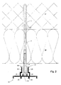
- a laser beam source is now positioned that the emitted by this (for example back and forth swept or rotating) light beam in one plane lies that corresponds to the desired or parallel to this is.
- the adjusting screw is now for example with a power screwdriver like this long rotated until the laser beam pivots on a screwdriver installed in or attached to the screwdriver Laser receiver hits.
- the laser receiver can now give an acoustic or visual signal that on it indicates that the desired screw-in depth has been reached.
- the laser receiver can also use the screwdriver automatically switch off. If this is done by just one person and can be carried out quickly and easily, for everyone the adjusting screws in the area of the laser beam the screw heads and thus the last supports are located all exactly on the same level.
- the Bar holder or the head of the adjusting screw a mark be attached, with the help of the desired screw depth be checked visually for the laser beam can.
- the marking can be a pierced ring on the outside of the head a hexagon socket screw, but also the top or bottom edge of this head.
- a power screwdriver that switches on when it is pressed into the hexagon socket and turns off when a laser beam receiver attached to it is hit by the laser beam. That way you can the adjusting screws and thus the last holder whole wall in no time, but with unprecedented Precision.
- the subsequent attachment of the Last only requires that one last on the last holder a number of fasteners is placed, after the elongated formations of the last holder towards the bar were about aligned, and then everyone the corresponding last holder is gripped by a tool and is rotated by about 90 ° until the spring legs snap into place becomes audible. All strips of the corresponding wall are exactly in one and the same after this simple assembly Level, so that the assembly of stone facade panels or the like. can now be done without difficulty.
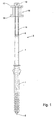
- Fig. 1 shows a dowel 1 made of plastic, in which a screw 3 is screwed in steel, consisting of a bolt 5 and one Sleeve 7 is made.
- the bolt 5 is designed like a wood screw, so that it can be screwed into the dowel 1 quickly can and spreads the dowel 1 apart.
- the bolt 5 faces away from the wood screw tip, a cylindrical End that is bounded by a shoulder towards the wood screw is.
- the sleeve is on this cylindrical end up to the shoulder 7 pushed out of a seamlessly drawn steel tube exists, the inside diameter of which is the outside diameter of said cylindrical end corresponds substantially.
- the Sleeve 7 is pressed or welded to this end. Outdoors At the end, the sleeve 7 has an internal thread 9 which extends over extends a considerable length into the sleeve 7.
- the diameter of this internal thread is quite small and is preferably M6.
- the sleeve 7 is vertical from the wall 27 when the dowel 1 in a hole in a wall 27 is inserted, and passes through an insulating layer 29, which is applied to the wall 27. This corresponds to the length of the sleeve 7 approximately the thickness of the insulating layer 29th
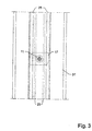
- This last bracket 15 is best from the oblique view 4 can be seen. It has a flat, elongated Plate 17, which extends perpendicular to the bore, the is penetrated by the shaft 11. The one facing away from screw 3 Surface of the plate 17 forms an abutment for the underside the head 13 of the adjusting screw 11, 13.
- the plate 17, which is centered on the adjusting screw 11, 13 is essentially rectangular, with the exception that that they are rounded off at two diagonally opposite corners is (see Fig. 3). This plate 17 is on the Screw 3 remote end of the strip holder 15 is formed.
- the screw 3 facing end are on the strip holder 15 two spring legs 19 formed, which are axially parallel to plate 17 and each other with respect to the center of the last holder Extend 15 opposite.
- the spring legs 19 each have the free side End a protruding wart.
- the last holder can be made of plastic or metal, preferably made of a light metal alloy.
- the strip 31 is partly complementary to the strip holder 15 educated.
- the strip 31 is preferably an extruded one Profile bar and has a flat, elongated plate that extends extends parallel to wall 27 and one on either side Stand out row of longitudinal webs.
- the plate supports On the other side facing the wall, the plate supports also four webs, of which two each to the longitudinal center of the Plate are arranged symmetrically. Near the middle are two low webs 23 formed, the height of the height of the head 13 corresponds to the adjusting screw 11, 13. The distance between the two low webs 23 correspond to the diameter of the screw head 13.
- the other two webs 25 are cranked toward one another and outside the low webs 23 on the plate of the bar 31st stated.
- the cranked webs 25 extend from the Plate of bar 31 from perpendicular to this by a distance, the height of the low ridges plus the thickness of the elongated ones Plate 17 corresponds, then the cranks extend parallel to the plate of the bar 31 towards each other and they go then in end sections perpendicular to this plate.
- the padding between these vertical end sections the length of the narrow side of the elongated plate 17 is not below.
- the distance between the outer edges of the ends of the cranked webs is a little smaller than the distance between the warts of the two spring legs 19th
- the two cranked legs 25 thus form between each other an interior 21 which is open to the wall 27 and on both sides is undercut. Extend into this interior 21 the two lower webs 23.
- the distance from the interior 21 to the free ends of the cranked Web 25 corresponds to the distance between the elongated Plate 17 and the spring legs 19 of the last holder 15th
- the dowel holes are drilled first.
- the Dowels 1 are already pre-assembled with the fasteners and thus form a composite unit. This unity is inserted into the dowel holes in one operation by for example, the unit is hammered in, until the dowel 1 is flush with the masonry 27. Then the ends 5 of the screws 3 are screwed into the dowels 1 and the fastener is thus fixed in the masonry 27.
- Pre-assembled strip holder 15 does not constitute an essential one Disability, since at this time the last holder 15 free with regard to screw 3 and adjusting screw 11, 13 can twist.
- the bar 31 is then lightly pressed against the wall 27, so that the free transverse surfaces the heads 13 of the adjusting screws 11, 13 between the low ridges 23 of the bar 31 and are on the wall side sit on the plate of this bar 31.
- the strip holder 15 is gripped by a tool, if necessary, pressed against the bar 31 and rotated by about 90 °.
- the elongated plate 17 sits on the free edges of the low webs 23 and engages behind when twisted the undercuts formed by the cranked webs 25 are.
- the diagonally opposite roundings (Fig. 3) allow twisting, the non-rounded corners of the elongated Plate 17, however, provide an end stop.
Landscapes
- Engineering & Computer Science (AREA)
- Architecture (AREA)
- Civil Engineering (AREA)
- Structural Engineering (AREA)
- Connection Of Plates (AREA)
- Finishing Walls (AREA)
Applications Claiming Priority (2)
| Application Number | Priority Date | Filing Date | Title |
|---|---|---|---|
| DE10054281 | 2000-11-02 | ||
| DE2000154281 DE10054281C2 (de) | 2000-11-02 | 2000-11-02 | Befestigungselement und Verfahren zu dessen Montage |
Publications (2)
| Publication Number | Publication Date |
|---|---|
| EP1203853A2 true EP1203853A2 (fr) | 2002-05-08 |
| EP1203853A3 EP1203853A3 (fr) | 2003-10-22 |
Family
ID=7661881
Family Applications (1)
| Application Number | Title | Priority Date | Filing Date |
|---|---|---|---|
| EP01122105A Withdrawn EP1203853A3 (fr) | 2000-11-02 | 2001-09-14 | Elément de fixation et méthode pour son montage |
Country Status (2)
| Country | Link |
|---|---|
| EP (1) | EP1203853A3 (fr) |
| DE (1) | DE10054281C2 (fr) |
Cited By (5)
| Publication number | Priority date | Publication date | Assignee | Title |
|---|---|---|---|---|
| EP2090716A1 (fr) * | 2008-02-15 | 2009-08-19 | Guido Berger Produktmanagement GmbH | Montage de mesure et procédé d'alignement de supports pour éléments de revêtement |
| CH708361A1 (de) * | 2013-07-22 | 2015-01-30 | Gasser Fassadentechnik Ag | Fassadenanker. |
| EP3348745A1 (fr) * | 2017-01-12 | 2018-07-18 | COOPERIO, besloten vennootschap met beperkte aansprakelijkheid | Procédé pour la finition d'une sous-structure d'un mur ou d'un toit et accessoire ainsi appliqué |
| EP3505704A1 (fr) * | 2017-12-29 | 2019-07-03 | Michele Farina | Structure de parement externe pour l'isolation thermique et acoustique des bâtiments |
| WO2021144243A1 (fr) * | 2020-01-14 | 2021-07-22 | Renson Sunprotection-Screens Nv | Ensemble de fixation doté d'un élément de fixation rotatif |
Families Citing this family (1)
| Publication number | Priority date | Publication date | Assignee | Title |
|---|---|---|---|---|
| EP1485549A1 (fr) | 2002-03-12 | 2004-12-15 | EJOT Baubefestigungen GmbH | Element de fixation |
Citations (1)
| Publication number | Priority date | Publication date | Assignee | Title |
|---|---|---|---|---|
| EP0921252A2 (fr) | 1997-12-02 | 1999-06-09 | SFS Industrie Holding AG | Elément de fixation pour la fixation à distance de lattes, profilés, panneaux ou similaires sur un support fix, guide de perçage pour trous dans un fond, pour l'insertion d'éléments de fixation et procédé pour la fixation à distance à l'aide d'un tel élément de fixation |
Family Cites Families (7)
| Publication number | Priority date | Publication date | Assignee | Title |
|---|---|---|---|---|
| CH549140A (de) * | 1972-09-07 | 1974-05-15 | Neomat Ag | Haltevorrichtung fuer fassaden- und innenwandverkleidungen. |
| CH598438A5 (en) * | 1976-12-23 | 1978-04-28 | Braendli August | Clamp for facing and internal lining panels for wall or ceiling |
| DE3127736A1 (de) * | 1981-07-14 | 1983-02-10 | Albert 7251 Hemmingen Fink | "vorrichtung zum befestigen einer fassadenverkleidungs-unterkonstruktion an einer gebaeudewand" |
| DE3337711C2 (de) * | 1983-10-18 | 1986-01-16 | Berger, Erich, 7137 Sternenfels | Befestigung einer Platte mit Zwischenraum an einem stabilen Träger |
| SE505841C2 (sv) * | 1996-01-19 | 1997-10-13 | Kent Blom | Regelsystem med nivåjusteringsorgan |
| EP0870886B1 (fr) * | 1997-04-11 | 2003-11-12 | Dieter Peterhans | Dispositif de nivelage d'un objet |
| DE19910511B4 (de) * | 1999-03-10 | 2005-03-17 | Witte-Velbert Gmbh & Co. Kg | Vorrichtung zum verspannenden Verbinden von mit Abstand zueinanderliegenden Bauteilen |
-
2000
- 2000-11-02 DE DE2000154281 patent/DE10054281C2/de not_active Expired - Fee Related
-
2001
- 2001-09-14 EP EP01122105A patent/EP1203853A3/fr not_active Withdrawn
Patent Citations (1)
| Publication number | Priority date | Publication date | Assignee | Title |
|---|---|---|---|---|
| EP0921252A2 (fr) | 1997-12-02 | 1999-06-09 | SFS Industrie Holding AG | Elément de fixation pour la fixation à distance de lattes, profilés, panneaux ou similaires sur un support fix, guide de perçage pour trous dans un fond, pour l'insertion d'éléments de fixation et procédé pour la fixation à distance à l'aide d'un tel élément de fixation |
Cited By (10)
| Publication number | Priority date | Publication date | Assignee | Title |
|---|---|---|---|---|
| EP2090716A1 (fr) * | 2008-02-15 | 2009-08-19 | Guido Berger Produktmanagement GmbH | Montage de mesure et procédé d'alignement de supports pour éléments de revêtement |
| CH708361A1 (de) * | 2013-07-22 | 2015-01-30 | Gasser Fassadentechnik Ag | Fassadenanker. |
| EP2853654A2 (fr) | 2013-07-22 | 2015-04-01 | Gasser Fassadentechnik AG | Console et infrastructure de façade dotée d'une telle console |
| EP2853654B1 (fr) * | 2013-07-22 | 2022-09-07 | GFT Fassaden AG | Console et infrastructure de façade dotée d'une telle console |
| EP3348745A1 (fr) * | 2017-01-12 | 2018-07-18 | COOPERIO, besloten vennootschap met beperkte aansprakelijkheid | Procédé pour la finition d'une sous-structure d'un mur ou d'un toit et accessoire ainsi appliqué |
| BE1024890B1 (nl) * | 2017-01-12 | 2018-08-21 | Cooperio Bvba | Werkwijze voor het afwerken van een onderstructuur van een gevel of een dak en hulpstuk daarbij toegepast |
| EP3505704A1 (fr) * | 2017-12-29 | 2019-07-03 | Michele Farina | Structure de parement externe pour l'isolation thermique et acoustique des bâtiments |
| WO2021144243A1 (fr) * | 2020-01-14 | 2021-07-22 | Renson Sunprotection-Screens Nv | Ensemble de fixation doté d'un élément de fixation rotatif |
| BE1027985B1 (nl) * | 2020-01-14 | 2021-08-16 | Renson Sunprotection Screens Nv | Bevestigingselement |
| US12234852B2 (en) | 2020-01-14 | 2025-02-25 | Renson Nv | Fastening element |
Also Published As
| Publication number | Publication date |
|---|---|
| DE10054281C2 (de) | 2003-02-06 |
| DE10054281A1 (de) | 2002-05-29 |
| EP1203853A3 (fr) | 2003-10-22 |
Similar Documents
| Publication | Publication Date | Title |
|---|---|---|
| EP0375089B1 (fr) | Support de traverses pour murs rideaux | |
| EP0136431B1 (fr) | Ossature en profilés | |
| EP0490086B1 (fr) | Raccord à vis pour assembler au moins deux pièces de manière détachable, notamment des barres profilées pourvues de rainures longitudinales | |
| DE202007018765U1 (de) | Halterung für Verkleidungselemente bzw. eine Unterkonstruktion für Verkleidungselemente | |
| WO1992010687A1 (fr) | Procede et dispositif pour la fixation d'un objet sur une paroi en materiau de construction leger | |
| DE10054281C2 (de) | Befestigungselement und Verfahren zu dessen Montage | |
| DE3127736A1 (de) | "vorrichtung zum befestigen einer fassadenverkleidungs-unterkonstruktion an einer gebaeudewand" | |
| CH671255A5 (en) | Holder on facade cladding - has rail accommodating sliding nut and with U=sections and springs gripping panels | |
| EP1729018B1 (fr) | Système d'assemblage de profilés | |
| EP1640621B1 (fr) | Pièce de barre ou d'armature avec la coupe transversale rectangulaire pour un système à la construction des dispositifs fixent des objets | |
| EP0166320B1 (fr) | Fenêtre avec grillage à petits bois apposés | |
| CH633621A5 (en) | Structural element set for connecting in each case two profiles which abut against one another at any angle | |
| CH695023A5 (de) | Befestigungselement und Verfahren zu dessen Montage. | |
| DE3001026A1 (de) | Vorrichtung zur befestigung eines beschlages in einem fluegelprofil fuer fenster oder tueren | |
| DE3743041C1 (en) | Method for producing a frame element consisting of interconnected hollow-profile beams and punching device for carrying out the method | |
| DE2921525A1 (de) | Treppen-handlauf und vorrichtung zu seiner befestigung | |
| DE4237019C2 (de) | Verbindung zwischen zwei oder mehreren Profilelementen oder zwischen Montageteilen und einem oder mehreren Profilelementen | |
| DE3801060A1 (de) | Befestigungs- und ausgleichsvorrichtung, insbesondere fuer unterkonstruktionen | |
| DE9419943U1 (de) | Geländer für Treppen, Brüstungen o.dgl. | |
| EP0527999A1 (fr) | Vis pour trous borgnes de faible profondeur. | |
| EP3748170B1 (fr) | Système de fixation pour une plaque, un mur ou analogues | |
| DE4444279C2 (de) | Geländer für Treppen, Brüstungen oder dergleichen | |
| DE102023124876A1 (de) | Bohrlehre für Exzenter-Schraubdübel-Verbinder | |
| DE29819228U1 (de) | Verbindungselement für Bauteile und Verbindungsanordnung | |
| DE10309793A1 (de) | Brennschneidmaschine mit einer Führungsschiene und Vorrichtung zum Ausrichten derselben |
Legal Events
| Date | Code | Title | Description |
|---|---|---|---|
| PUAI | Public reference made under article 153(3) epc to a published international application that has entered the european phase |
Free format text: ORIGINAL CODE: 0009012 |
|
| AK | Designated contracting states |
Kind code of ref document: A2 Designated state(s): AT BE CH CY DE DK ES FI FR GB GR IE IT LI LU MC NL PT SE TR |
|
| AX | Request for extension of the european patent |
Free format text: AL;LT;LV;MK;RO;SI |
|
| PUAL | Search report despatched |
Free format text: ORIGINAL CODE: 0009013 |
|
| AK | Designated contracting states |
Kind code of ref document: A3 Designated state(s): AT BE CH CY DE DK ES FI FR GB GR IE IT LI LU MC NL PT SE TR |
|
| AX | Request for extension of the european patent |
Extension state: AL LT LV MK RO SI |
|
| 17P | Request for examination filed |
Effective date: 20031112 |
|
| AKX | Designation fees paid |
Designated state(s): AT BE CH CY DE DK ES FI FR GB GR IE IT LI LU MC NL PT SE TR |
|
| 17Q | First examination report despatched |
Effective date: 20060714 |
|
| 17Q | First examination report despatched |
Effective date: 20060714 |
|
| GRAP | Despatch of communication of intention to grant a patent |
Free format text: ORIGINAL CODE: EPIDOSNIGR1 |
|
| STAA | Information on the status of an ep patent application or granted ep patent |
Free format text: STATUS: THE APPLICATION IS DEEMED TO BE WITHDRAWN |
|
| 18D | Application deemed to be withdrawn |
Effective date: 20071001 |