EP3348745A1 - Procédé pour la finition d'une sous-structure d'un mur ou d'un toit et accessoire ainsi appliqué - Google Patents
Procédé pour la finition d'une sous-structure d'un mur ou d'un toit et accessoire ainsi appliqué Download PDFInfo
- Publication number
- EP3348745A1 EP3348745A1 EP18150943.1A EP18150943A EP3348745A1 EP 3348745 A1 EP3348745 A1 EP 3348745A1 EP 18150943 A EP18150943 A EP 18150943A EP 3348745 A1 EP3348745 A1 EP 3348745A1
- Authority
- EP
- European Patent Office
- Prior art keywords
- holes
- base plate
- substructure
- support slat
- panels
- Prior art date
- Legal status (The legal status is an assumption and is not a legal conclusion. Google has not performed a legal analysis and makes no representation as to the accuracy of the status listed.)
- Granted
Links
- 238000000034 method Methods 0.000 title claims abstract description 34
- 238000009413 insulation Methods 0.000 claims abstract description 58
- 238000005253 cladding Methods 0.000 claims abstract description 15
- 230000001105 regulatory effect Effects 0.000 claims abstract description 6
- 238000009434 installation Methods 0.000 claims abstract 2
- 229910052751 metal Inorganic materials 0.000 claims description 9
- 239000002184 metal Substances 0.000 claims description 9
- 230000002787 reinforcement Effects 0.000 claims description 2
- HCHKCACWOHOZIP-UHFFFAOYSA-N Zinc Chemical compound [Zn] HCHKCACWOHOZIP-UHFFFAOYSA-N 0.000 description 4
- 239000004411 aluminium Substances 0.000 description 4
- 229910052782 aluminium Inorganic materials 0.000 description 4
- XAGFODPZIPBFFR-UHFFFAOYSA-N aluminium Chemical compound [Al] XAGFODPZIPBFFR-UHFFFAOYSA-N 0.000 description 4
- 239000000463 material Substances 0.000 description 4
- 239000011701 zinc Substances 0.000 description 4
- 229910052725 zinc Inorganic materials 0.000 description 4
- 239000000919 ceramic Substances 0.000 description 2
- 239000011505 plaster Substances 0.000 description 2
- 238000010079 rubber tapping Methods 0.000 description 2
- 239000002023 wood Substances 0.000 description 2
- RYGMFSIKBFXOCR-UHFFFAOYSA-N Copper Chemical compound [Cu] RYGMFSIKBFXOCR-UHFFFAOYSA-N 0.000 description 1
- 239000011449 brick Substances 0.000 description 1
- 239000002131 composite material Substances 0.000 description 1
- 238000010276 construction Methods 0.000 description 1
- 239000010949 copper Substances 0.000 description 1
- 229910052802 copper Inorganic materials 0.000 description 1
- 238000011161 development Methods 0.000 description 1
- 230000018109 developmental process Effects 0.000 description 1
- 239000011518 fibre cement Substances 0.000 description 1
- 238000009418 renovation Methods 0.000 description 1
- 239000004575 stone Substances 0.000 description 1
- 229920002994 synthetic fiber Polymers 0.000 description 1
Images


Classifications
-
- E—FIXED CONSTRUCTIONS
- E04—BUILDING
- E04F—FINISHING WORK ON BUILDINGS, e.g. STAIRS, FLOORS
- E04F13/00—Coverings or linings, e.g. for walls or ceilings
- E04F13/07—Coverings or linings, e.g. for walls or ceilings composed of covering or lining elements; Sub-structures therefor; Fastening means therefor
- E04F13/08—Coverings or linings, e.g. for walls or ceilings composed of covering or lining elements; Sub-structures therefor; Fastening means therefor composed of a plurality of similar covering or lining elements
- E04F13/0801—Separate fastening elements
- E04F13/0803—Separate fastening elements with load-supporting elongated furring elements between wall and covering elements
- E04F13/0805—Separate fastening elements with load-supporting elongated furring elements between wall and covering elements with additional fastening elements between furring elements and the wall
- E04F13/0807—Separate fastening elements with load-supporting elongated furring elements between wall and covering elements with additional fastening elements between furring elements and the wall adjustable perpendicular to the wall
Definitions
- the present invention relates to a method for the finishing of a substructure of a wall or a roof.
- a finish is provided with a cladding in the form of roof tiles, roof panels or the like in the event of a roof or in the form of decorative panels or panels against which bricks, plaster, or the like are applied in the event of a wall.
- a load-bearing frame is installed on the substructure of the roof or wall with slats or panels against which the finish is provided.
- the insulation panels are placed between load-bearing wooden constructions.
- This technique is not recommended as the load-bearing frame shows considerable nodes. Moreover, this technique has a real and considerable risk of thermal bridges.
- a first known continuous insulation technique uses a wooden frame whereby in a first phase the thermal insulation is applied against or on the substructure and the wooden frame using set screws.
- a second known insulation technique with continuous uninterrupted insulation panels uses an aluminium frame with thermal break whereby the load-bearing frame, by means of special L-shaped brackets which are attached with one leg on the substructure and with the other leg stick through the insulation panels to attach the load-bearing frame with slats or panels.
- the weak points of this technique are the following:
- the purpose of the present invention is to offer a solution for one or more of the aforementioned and other disadvantages and weak points.
- the invention relates to a method for the finishing of a substructure of a wall or a roof, whereby first thermal insulation panels are adjoined against each other on the substructure and then a cladding is applied on a load-bearing frame in the form of slats, panels or the like which are attached on the substructure, characterised in that the slats, panels or the like of the load-bearing frame are attached on the substructure by means of one or more accessories in the form of a base plate which is attached ⁇ on the substructure against the side of the insulation panels turned away from the substructure and which is fitted with a regulating rod or adjusting screw with a top in the form of an attachment element for the slats, panels or the like, whereby after the placing of the accessories the regulating rods or adjustment screws in relation to the base plate can be adjusted to align the slats, panels or the like of the load-bearing frame with each other in a plane.
- the method according to the invention is suitable both for new developments and for renovation to quickly, efficiently, continuously and sustainably insulate walls.
- the unique adjusting system with the aforementioned accessories ensures that every wall can quickly and simply be aligned and is perfectly suited for all ventilated wall applications.
- the method is extra handy to align the load-bearing frame by making the adjustment screws looser or tighter, e.g. using a drill with an adapted bit to be able to grip the attachment elements.
- a ground laser With a ground laser the load-bearing frame can be aligned very accurately and in little time such that considerable time savings can be made and less working hours are required.
- the wall can be finished in wood, synthetic material, composite, zinc, copper, aluminium, fibre cement and ceramic applications, slabs with plaster, and the like.
- the insulation panels form an uninterrupted insulation shield as it were without thermal bridges.
- the accessories can be simply attached to the substructure using screws that are screwed through the provided holes in the base plate and through the insulation panels in the substructure.
- the accessories can be screwed on a support slat fitted against the side of the insulation panels turned away from the substructure and is connected with the substructure by means of screws that are screwed through the provided holes in the support slat and through the insulation panels in the substructure.
- the method uses insulation panels that across the length of one of their edges are provided with an aforementioned support slat which is attached in/on the insulation panel in question and sticks out with a certain width over the aforementioned edge of the insulation panel to form a protruding lip.
- a laser is used for the alignment of the slats, panels or the like of the load-bearing frame such that a quick and exact alignment are possible.
- the invention also relates to an accessory for use in the method according to the invention, whereby the accessory is composed of a base plate and an adjusting screw which in relation to the base plate can be tightened or loosened in a direction perpendicular to the base plate and which is fitted with a top in the form of an attachment element for the attachment of the slats, panels or the like of the load-bearing frame.
- This accessory can be manufactured very simply and cheaply.
- the invention also relates to a combination of an accessory as aforementioned and of a support slat, whereby the support slat has a pattern with holes along two opposite edges located at a fixed distance from each other which is such that the base plate of an accessory can be positioned in such a way on the support slat that holes of the base plate correspond in position with a number of holes of the support slat.
- the support slat and the accessory can be affixed to the substructure with the same screws.
- the accessory and/or the support slat are made of metal.
- the insulation panels are attached to the wall.
- the support slats thus form a new fixed structure on which a non-ventilated finish (zinc and the like) can be directly installed without the use of accessories.
- a ventilated wooden or metal load-bearing frame can be easily mounted.
- This profile was designed in such a way that, depending on the weight of the wall cladding, it can be affixed with 2 or 4 self-tapping screws in the metal frame.
- For very heavy wall claddings slab, stone strips, and the like) there is also the possibility to affix the rail profiles in the metal frame into the wall via the pre-drilled screw holes.
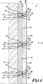
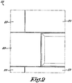
- the finished wall 1 shown in figures 1 and 2 is built on a substructure 2 which in this case is formed by an inner leaf of a wall.
- insulation panels 3 are attached in the known way which with their edges 4 and 5, the bottom edge 4 and top edge 5 respectively, and with their side edges which are connected to each other to form an insulating skin that is as good as closed around the substructure 2 of the wall 1.
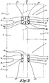
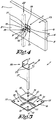
- an accessory 7 according to the invention is affixed as shown in figure 5 and in the way as shown in figures 1 , 3 and 4 in case light finishing materials are used.
- the accessory is composed of a base plate 8 and an adjusting screw 9, preferably metal.
- the base plate 8 is a square base plate with a central screw passage 10 which in this case is formed by a nut 11 that is welded on the base plate 8 opposite a passage 12 in the base plate 8.
- the base plate 8 is also provided with a first series of holes 13 near the corners of the base plate 8 on a fixed radial distance A of the central screw passage 10 and situated on the corners of an imaginary square 14 that is shown in a dashed line in figure 8 with a side with length B.
- a second series of holes 15 is provided in the base plate 8 at a fixed radial distance C of the central screw passage 10 that is smaller than the aforementioned distance A and which is located on the diagonals of the aforementioned imaginary square 14.
- the base plate 8 is provided with radial protruding reinforcements 16 in relation to the screw passage 10, e.g. in the form of embossed sunken parts.
- the adjusting screw 9 is formed by a threaded rod 17 which is screwed in the screw passage 12 and which on one end is fitted with an attachment element 18 which in this case is to attach slats 19 and for this is made as a U-shaped folded element with legs 20 which extend parallel to the longitudinal direction X-X' of the threaded rod 17, such that a slat 19 can be attached between the legs 20.
- the accessories 7 with are affixed with their holes 13 vertically above each other against the insulation panels 3 and using screws 21 or the like attached through the holes 15 of the base plate 8 and through the insulation panels on the substructure 2 as shown in figure 1 .
- the adjustment screws of the placed accessories are tightened or loosened to align the attachment elements 18 in relation to each other in the same plane, in this case in a vertical plane, so that the slats 19 affixed in it, together with those already affixed in it, form a flat aligned load-bearing frame 22 of e.g. vertical or horizontal slats against which e.g. finishing panels or another cladding 23 can be attached in the known way.
- the aligning is preferably done using a laser, although other known techniques also come into consideration for this.
- the cladding 23 can be attached directly to the load-bearing frame 22.
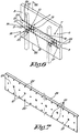
- the accessories 7 in the majority of cases using a support slat 24 of metal or the like, are attached to the substructure 2 as shown in the figures 6 and 9 .
- the support slat 24 forms a fixed structure as it were that will offset the forces exercised on the accessories 7 and distribute the forces of several accessories which are attached to support slat 24 better over the length of the support slat 24.
- the support slat 24 is provided for example with holes 25 for the screws 21 with a pattern of holes that is such that the accessories 7 can be aligned with their holes 13 opposite the holes 25.
- the support slat 24 shows two series of holes 25, respectively holes 25' and holes 25", that are located along two opposite edges of the support slat 24 according to two parallel lines at a distance D from each other which is the same as the aforementioned distance B between the holes 13 and for every series of holes 25' and 25" an intermediate centre distance E which amounts to half of the aforementioned distance B.
- the support slats 24 can at the level of the holes 25 form a seat for the screw heads 21, such that the screws 21 with a sunken head fit under the base plate 8 of the accessory 7.
- the support slat 24 with the screws 21 can be fixed in the substructure 2 and the accessories 7 in turn can be screwed tight using self-tapping screws 26 or the like through the holes 15 in the base plate 8 in the support slat 24 as illustrated in figure 9 .
- the support slats 24 can still be fitted with an additional series of holes 27, possibly to make room for the nuts 11 of the accessories 7.
- the support slats 24 can also be integrated in the insulation panels 3, whereby the support slat 24 is attached on the aforementioned side 6 of the insulation panel 3 and sticks out over the length of the bottom edge 4 of the insulation panel 3.
- the support slat 24 sticks out with a certain width F over this edge 4 like a downward protruding lip 28 which can be affixed overlapping against an adjacent insulation panel 3 on this edge 4, whereby the holes 25" on the level of this lip 8 are provided above one insulation panel 3 and the other holes 25' on the level of the adjacent insulation panel 3.
- the support slats 24 thus always support on two insulation panels 3.
- the integrated support slats 24 can also be fitted, along one edge, with a perpendicular folded back lip 29 which is imbedded in the material of the insulation panel 3 and results in a greater stability.
- insulation panels 3 with the pattern of holes of their support slats 24 are aligned in a vertical or horizontal direction, it is easier to align the accessories 7 correspondingly in a vertical or horizontal direction with each other by aligning them with their holes 13 on corresponding holes of the support slats 24 on a vertical or horizontal line.
- accessories 7 is applicable in ventilated applications whereby a ventilated air gap 30 between the insulation panels 3 and the cladding 23 is necessary.
- Such insulation panels 3 with integrated support slats 24 can also be used according to another aspect of the invention for non-ventilated applications without accessories 7 if the cladding 23 is affixed against the insulation panels 3 without air gap between the insulation and the cladding. This is the case for instance for a finish with zinc.
- the holes 25 can then be used to attach zinc layers.
- the invention is not only meant for the finishing of a wall, but is just as applicable to other substructures 2, such as a roof structure or the like.
- FIG. 10 shows an example of an adjusting screw 9 with a flat attachment element 18 that extends as it were in the extension of the threaded rod 17 and which is suitable, for example, for slats 19 made out of aluminium instead of wood.
- the adjusting screw 9 is in this case provided with a round hole 31 and slip hole 32 for a screw passage for the attachment of the slats by means of screws.
- the round hole 31 can be used for a fixed connection, e.g. at one end of a slat 19, whereas the slip hole 32 can be used for a sliding connection in another point of the slat 19 at a distance from the fixed connection, and this to offset the contracting and shrinking of the aluminium following temperature fluctuations. In this way both attachments can be realised with one single type of adjusting screw 9.
- the invention is not restricted to the alignment of the load-bearing frame in a straight plane, but is also applicable for a curved plane.
- a depth adjustable rod can also be used which can be held, e.g. with clamping means or the like in its set position.
- the present invention is in no way whatsoever restricted to the embodiments shown by way of an example and in the figures, but a method according to the invention for the finishing of a substructure 2 of a wall or of a roof and of a thereby applied accessory possibly in combination with a support slat, which can be realised in all kinds of forms and dimensions, without departing from the scope of the invention.
Landscapes
- Engineering & Computer Science (AREA)
- Architecture (AREA)
- Civil Engineering (AREA)
- Structural Engineering (AREA)
- Finishing Walls (AREA)
Applications Claiming Priority (1)
| Application Number | Priority Date | Filing Date | Title |
|---|---|---|---|
| BE2017/5014A BE1024890B1 (nl) | 2017-01-12 | 2017-01-12 | Werkwijze voor het afwerken van een onderstructuur van een gevel of een dak en hulpstuk daarbij toegepast |
Publications (2)
| Publication Number | Publication Date |
|---|---|
| EP3348745A1 true EP3348745A1 (fr) | 2018-07-18 |
| EP3348745B1 EP3348745B1 (fr) | 2019-10-30 |
Family
ID=57962957
Family Applications (1)
| Application Number | Title | Priority Date | Filing Date |
|---|---|---|---|
| EP18150943.1A Active EP3348745B1 (fr) | 2017-01-12 | 2018-01-10 | Procédé pour la finition d'une sous-structure d'un mur ou d'un toit et accessoire ainsi appliqué |
Country Status (2)
| Country | Link |
|---|---|
| EP (1) | EP3348745B1 (fr) |
| BE (1) | BE1024890B1 (fr) |
Cited By (1)
| Publication number | Priority date | Publication date | Assignee | Title |
|---|---|---|---|---|
| CN114033120A (zh) * | 2021-11-17 | 2022-02-11 | 瑞宇建设有限公司 | 建筑干挂石材墙体建造施工方法 |
Citations (6)
| Publication number | Priority date | Publication date | Assignee | Title |
|---|---|---|---|---|
| US2167176A (en) * | 1937-09-16 | 1939-07-25 | Karl P Grassberger | Wall fastening |
| US3889439A (en) * | 1973-06-29 | 1975-06-17 | Neomat Ag | Device for holding front wall or inside wall facings as well as inside or outside facings of a ceiling in a pre-set distance from a supporting wall respectively a ceiling |
| EP1046764A1 (fr) * | 1999-04-22 | 2000-10-25 | Holzinger, Alois, sen. | Dispositif pour la fixation à distance de plaques d'isolation aux murs ou aux plafonds |
| EP1203853A2 (fr) * | 2000-11-02 | 2002-05-08 | Werner Müller | Elément de fixation et méthode pour son montage |
| DE10158108A1 (de) * | 2001-11-27 | 2003-06-05 | Martin Westhoff | Vorrichtung zur Befestigung von Wandverkleidungselementen auf tragenden Wänden |
| WO2003076739A1 (fr) * | 2002-03-12 | 2003-09-18 | Ejot Baubefestigungen Gmbh | Element de fixation |
-
2017
- 2017-01-12 BE BE2017/5014A patent/BE1024890B1/nl not_active IP Right Cessation
-
2018
- 2018-01-10 EP EP18150943.1A patent/EP3348745B1/fr active Active
Patent Citations (6)
| Publication number | Priority date | Publication date | Assignee | Title |
|---|---|---|---|---|
| US2167176A (en) * | 1937-09-16 | 1939-07-25 | Karl P Grassberger | Wall fastening |
| US3889439A (en) * | 1973-06-29 | 1975-06-17 | Neomat Ag | Device for holding front wall or inside wall facings as well as inside or outside facings of a ceiling in a pre-set distance from a supporting wall respectively a ceiling |
| EP1046764A1 (fr) * | 1999-04-22 | 2000-10-25 | Holzinger, Alois, sen. | Dispositif pour la fixation à distance de plaques d'isolation aux murs ou aux plafonds |
| EP1203853A2 (fr) * | 2000-11-02 | 2002-05-08 | Werner Müller | Elément de fixation et méthode pour son montage |
| DE10158108A1 (de) * | 2001-11-27 | 2003-06-05 | Martin Westhoff | Vorrichtung zur Befestigung von Wandverkleidungselementen auf tragenden Wänden |
| WO2003076739A1 (fr) * | 2002-03-12 | 2003-09-18 | Ejot Baubefestigungen Gmbh | Element de fixation |
Cited By (1)
| Publication number | Priority date | Publication date | Assignee | Title |
|---|---|---|---|---|
| CN114033120A (zh) * | 2021-11-17 | 2022-02-11 | 瑞宇建设有限公司 | 建筑干挂石材墙体建造施工方法 |
Also Published As
| Publication number | Publication date |
|---|---|
| BE1024890A1 (nl) | 2018-08-07 |
| BE1024890B1 (nl) | 2018-08-21 |
| EP3348745B1 (fr) | 2019-10-30 |
Similar Documents
| Publication | Publication Date | Title |
|---|---|---|
| EP3569792B1 (fr) | Structure de mur pour bâtiment, dispositif d'installation et procédé de construction de panneau | |
| US11441318B2 (en) | Modular staircase and method of constructing same | |
| DE202008004981U1 (de) | Mit Platten versehener Übergangshaltewinkel | |
| US20090249711A1 (en) | Outdoor Flooring and Assembly Method Thereof | |
| EP3348745B1 (fr) | Procédé pour la finition d'une sous-structure d'un mur ou d'un toit et accessoire ainsi appliqué | |
| US10024054B2 (en) | Facade construction | |
| DE102012221746B4 (de) | Wandheizelement | |
| EP3587690A1 (fr) | Vis d'ajustement, ensemble et procédé de mise à niveau d'un plancher hors niveau | |
| US20230228098A1 (en) | Cladding system | |
| DE10007101A1 (de) | Nivelliervorrichtung für gerade Flächen | |
| EP2910706B1 (fr) | Elément de montage pour suspendre à distance un habillage de façade sur un mur de bâtiment | |
| DE4031864A1 (de) | Fussbodenstuetze fuer einstellbare auflegefussboeden und damit zu verlegender plattenfussboden | |
| US20140373477A1 (en) | Device For Correction Inconsistencies In Walls or Ceilings | |
| DE102015100678A1 (de) | Vorrichtung zum Befestigen von Verblendsteinen, insbesondere für den Fassadenbau, Trägerprofil und Verblendstein | |
| KR20070063196A (ko) | 천정재 부착용 경량철골 체결구 | |
| KR101479538B1 (ko) | 자석체를 이용한 건물 바닥 시공구조 | |
| AU2015271993A1 (en) | Apparatus and Method for Mounting Building Panels to the Framework Assembly of a Wall Structure | |
| AU2010101096A4 (en) | Apparatus and Method for Mounting Building Panels to the Framework Assembly of a Wall Structure | |
| CH635155A5 (en) | Facing shuttering | |
| EP1090194A1 (fr) | Procede de fixation de panneaux de bardage externe et assemblage de coulisseaux et de profiles metalliques pour la mise en oeuvre dudit procede | |
| DE3025741A1 (de) | Dachteil fuer insbesondere schraegdaecher | |
| DE20115423U1 (de) | Verbunddämmelement | |
| DE1924078A1 (de) | Bauelementensatz zur Montage von Asbestzementtafeln od.dgl. an Waenden | |
| DE29904531U1 (de) | Hohlboden auf Basis einer profilierten Folie auf verstellbaren Stützen | |
| Drawings | SECTION 09 22 16 NON-STRUCTURAL METAL FRAMING PART 1-GENERAL 1.1 DESCRIPTION |
Legal Events
| Date | Code | Title | Description |
|---|---|---|---|
| PUAI | Public reference made under article 153(3) epc to a published international application that has entered the european phase |
Free format text: ORIGINAL CODE: 0009012 |
|
| STAA | Information on the status of an ep patent application or granted ep patent |
Free format text: STATUS: THE APPLICATION HAS BEEN PUBLISHED |
|
| AK | Designated contracting states |
Kind code of ref document: A1 Designated state(s): AL AT BE BG CH CY CZ DE DK EE ES FI FR GB GR HR HU IE IS IT LI LT LU LV MC MK MT NL NO PL PT RO RS SE SI SK SM TR |
|
| AX | Request for extension of the european patent |
Extension state: BA ME |
|
| STAA | Information on the status of an ep patent application or granted ep patent |
Free format text: STATUS: REQUEST FOR EXAMINATION WAS MADE |
|
| 17P | Request for examination filed |
Effective date: 20190108 |
|
| RBV | Designated contracting states (corrected) |
Designated state(s): AL AT BE BG CH CY CZ DE DK EE ES FI FR GB GR HR HU IE IS IT LI LT LU LV MC MK MT NL NO PL PT RO RS SE SI SK SM TR |
|
| GRAP | Despatch of communication of intention to grant a patent |
Free format text: ORIGINAL CODE: EPIDOSNIGR1 |
|
| STAA | Information on the status of an ep patent application or granted ep patent |
Free format text: STATUS: GRANT OF PATENT IS INTENDED |
|
| INTG | Intention to grant announced |
Effective date: 20190522 |
|
| GRAS | Grant fee paid |
Free format text: ORIGINAL CODE: EPIDOSNIGR3 |
|
| GRAA | (expected) grant |
Free format text: ORIGINAL CODE: 0009210 |
|
| STAA | Information on the status of an ep patent application or granted ep patent |
Free format text: STATUS: THE PATENT HAS BEEN GRANTED |
|
| AK | Designated contracting states |
Kind code of ref document: B1 Designated state(s): AL AT BE BG CH CY CZ DE DK EE ES FI FR GB GR HR HU IE IS IT LI LT LU LV MC MK MT NL NO PL PT RO RS SE SI SK SM TR |
|
| REG | Reference to a national code |
Ref country code: GB Ref legal event code: FG4D |
|
| REG | Reference to a national code |
Ref country code: CH Ref legal event code: EP |
|
| REG | Reference to a national code |
Ref country code: DE Ref legal event code: R096 Ref document number: 602018000975 Country of ref document: DE |
|
| REG | Reference to a national code |
Ref country code: AT Ref legal event code: REF Ref document number: 1196286 Country of ref document: AT Kind code of ref document: T Effective date: 20191115 |
|
| REG | Reference to a national code |
Ref country code: IE Ref legal event code: FG4D |
|
| REG | Reference to a national code |
Ref country code: NL Ref legal event code: FP |
|
| REG | Reference to a national code |
Ref country code: LT Ref legal event code: MG4D |
|
| PG25 | Lapsed in a contracting state [announced via postgrant information from national office to epo] |
Ref country code: NO Free format text: LAPSE BECAUSE OF FAILURE TO SUBMIT A TRANSLATION OF THE DESCRIPTION OR TO PAY THE FEE WITHIN THE PRESCRIBED TIME-LIMIT Effective date: 20200130 Ref country code: GR Free format text: LAPSE BECAUSE OF FAILURE TO SUBMIT A TRANSLATION OF THE DESCRIPTION OR TO PAY THE FEE WITHIN THE PRESCRIBED TIME-LIMIT Effective date: 20200131 Ref country code: PL Free format text: LAPSE BECAUSE OF FAILURE TO SUBMIT A TRANSLATION OF THE DESCRIPTION OR TO PAY THE FEE WITHIN THE PRESCRIBED TIME-LIMIT Effective date: 20191030 Ref country code: FI Free format text: LAPSE BECAUSE OF FAILURE TO SUBMIT A TRANSLATION OF THE DESCRIPTION OR TO PAY THE FEE WITHIN THE PRESCRIBED TIME-LIMIT Effective date: 20191030 Ref country code: BG Free format text: LAPSE BECAUSE OF FAILURE TO SUBMIT A TRANSLATION OF THE DESCRIPTION OR TO PAY THE FEE WITHIN THE PRESCRIBED TIME-LIMIT Effective date: 20200130 Ref country code: LT Free format text: LAPSE BECAUSE OF FAILURE TO SUBMIT A TRANSLATION OF THE DESCRIPTION OR TO PAY THE FEE WITHIN THE PRESCRIBED TIME-LIMIT Effective date: 20191030 Ref country code: PT Free format text: LAPSE BECAUSE OF FAILURE TO SUBMIT A TRANSLATION OF THE DESCRIPTION OR TO PAY THE FEE WITHIN THE PRESCRIBED TIME-LIMIT Effective date: 20200302 Ref country code: SE Free format text: LAPSE BECAUSE OF FAILURE TO SUBMIT A TRANSLATION OF THE DESCRIPTION OR TO PAY THE FEE WITHIN THE PRESCRIBED TIME-LIMIT Effective date: 20191030 Ref country code: LV Free format text: LAPSE BECAUSE OF FAILURE TO SUBMIT A TRANSLATION OF THE DESCRIPTION OR TO PAY THE FEE WITHIN THE PRESCRIBED TIME-LIMIT Effective date: 20191030 |
|
| PG25 | Lapsed in a contracting state [announced via postgrant information from national office to epo] |
Ref country code: IS Free format text: LAPSE BECAUSE OF FAILURE TO SUBMIT A TRANSLATION OF THE DESCRIPTION OR TO PAY THE FEE WITHIN THE PRESCRIBED TIME-LIMIT Effective date: 20200229 Ref country code: HR Free format text: LAPSE BECAUSE OF FAILURE TO SUBMIT A TRANSLATION OF THE DESCRIPTION OR TO PAY THE FEE WITHIN THE PRESCRIBED TIME-LIMIT Effective date: 20191030 Ref country code: RS Free format text: LAPSE BECAUSE OF FAILURE TO SUBMIT A TRANSLATION OF THE DESCRIPTION OR TO PAY THE FEE WITHIN THE PRESCRIBED TIME-LIMIT Effective date: 20191030 |
|
| PG25 | Lapsed in a contracting state [announced via postgrant information from national office to epo] |
Ref country code: AL Free format text: LAPSE BECAUSE OF FAILURE TO SUBMIT A TRANSLATION OF THE DESCRIPTION OR TO PAY THE FEE WITHIN THE PRESCRIBED TIME-LIMIT Effective date: 20191030 |
|
| PG25 | Lapsed in a contracting state [announced via postgrant information from national office to epo] |
Ref country code: ES Free format text: LAPSE BECAUSE OF FAILURE TO SUBMIT A TRANSLATION OF THE DESCRIPTION OR TO PAY THE FEE WITHIN THE PRESCRIBED TIME-LIMIT Effective date: 20191030 Ref country code: CZ Free format text: LAPSE BECAUSE OF FAILURE TO SUBMIT A TRANSLATION OF THE DESCRIPTION OR TO PAY THE FEE WITHIN THE PRESCRIBED TIME-LIMIT Effective date: 20191030 Ref country code: RO Free format text: LAPSE BECAUSE OF FAILURE TO SUBMIT A TRANSLATION OF THE DESCRIPTION OR TO PAY THE FEE WITHIN THE PRESCRIBED TIME-LIMIT Effective date: 20191030 Ref country code: DK Free format text: LAPSE BECAUSE OF FAILURE TO SUBMIT A TRANSLATION OF THE DESCRIPTION OR TO PAY THE FEE WITHIN THE PRESCRIBED TIME-LIMIT Effective date: 20191030 Ref country code: EE Free format text: LAPSE BECAUSE OF FAILURE TO SUBMIT A TRANSLATION OF THE DESCRIPTION OR TO PAY THE FEE WITHIN THE PRESCRIBED TIME-LIMIT Effective date: 20191030 |
|
| REG | Reference to a national code |
Ref country code: DE Ref legal event code: R097 Ref document number: 602018000975 Country of ref document: DE |
|
| REG | Reference to a national code |
Ref country code: AT Ref legal event code: MK05 Ref document number: 1196286 Country of ref document: AT Kind code of ref document: T Effective date: 20191030 |
|
| PG25 | Lapsed in a contracting state [announced via postgrant information from national office to epo] |
Ref country code: SK Free format text: LAPSE BECAUSE OF FAILURE TO SUBMIT A TRANSLATION OF THE DESCRIPTION OR TO PAY THE FEE WITHIN THE PRESCRIBED TIME-LIMIT Effective date: 20191030 Ref country code: MC Free format text: LAPSE BECAUSE OF FAILURE TO SUBMIT A TRANSLATION OF THE DESCRIPTION OR TO PAY THE FEE WITHIN THE PRESCRIBED TIME-LIMIT Effective date: 20191030 Ref country code: SM Free format text: LAPSE BECAUSE OF FAILURE TO SUBMIT A TRANSLATION OF THE DESCRIPTION OR TO PAY THE FEE WITHIN THE PRESCRIBED TIME-LIMIT Effective date: 20191030 |
|
| PLBE | No opposition filed within time limit |
Free format text: ORIGINAL CODE: 0009261 |
|
| STAA | Information on the status of an ep patent application or granted ep patent |
Free format text: STATUS: NO OPPOSITION FILED WITHIN TIME LIMIT |
|
| 26N | No opposition filed |
Effective date: 20200731 |
|
| PG25 | Lapsed in a contracting state [announced via postgrant information from national office to epo] |
Ref country code: LU Free format text: LAPSE BECAUSE OF NON-PAYMENT OF DUE FEES Effective date: 20200110 |
|
| PG25 | Lapsed in a contracting state [announced via postgrant information from national office to epo] |
Ref country code: AT Free format text: LAPSE BECAUSE OF FAILURE TO SUBMIT A TRANSLATION OF THE DESCRIPTION OR TO PAY THE FEE WITHIN THE PRESCRIBED TIME-LIMIT Effective date: 20191030 Ref country code: SI Free format text: LAPSE BECAUSE OF FAILURE TO SUBMIT A TRANSLATION OF THE DESCRIPTION OR TO PAY THE FEE WITHIN THE PRESCRIBED TIME-LIMIT Effective date: 20191030 |
|
| PG25 | Lapsed in a contracting state [announced via postgrant information from national office to epo] |
Ref country code: IE Free format text: LAPSE BECAUSE OF NON-PAYMENT OF DUE FEES Effective date: 20200110 |
|
| REG | Reference to a national code |
Ref country code: BE Ref legal event code: PD Owner name: EXTERNA BV; BE Free format text: DETAILS ASSIGNMENT: CHANGE OF OWNER(S), ASSIGNMENT; FORMER OWNER NAME: COOPERIO, BESLOTEN VENNOOTSCHAP MET BEPERKTE AANSPRAKELIJKHEID Effective date: 20210427 |
|
| REG | Reference to a national code |
Ref country code: CH Ref legal event code: PL |
|
| PG25 | Lapsed in a contracting state [announced via postgrant information from national office to epo] |
Ref country code: CH Free format text: LAPSE BECAUSE OF NON-PAYMENT OF DUE FEES Effective date: 20210131 Ref country code: LI Free format text: LAPSE BECAUSE OF NON-PAYMENT OF DUE FEES Effective date: 20210131 |
|
| PG25 | Lapsed in a contracting state [announced via postgrant information from national office to epo] |
Ref country code: TR Free format text: LAPSE BECAUSE OF FAILURE TO SUBMIT A TRANSLATION OF THE DESCRIPTION OR TO PAY THE FEE WITHIN THE PRESCRIBED TIME-LIMIT Effective date: 20191030 Ref country code: MT Free format text: LAPSE BECAUSE OF FAILURE TO SUBMIT A TRANSLATION OF THE DESCRIPTION OR TO PAY THE FEE WITHIN THE PRESCRIBED TIME-LIMIT Effective date: 20191030 Ref country code: CY Free format text: LAPSE BECAUSE OF FAILURE TO SUBMIT A TRANSLATION OF THE DESCRIPTION OR TO PAY THE FEE WITHIN THE PRESCRIBED TIME-LIMIT Effective date: 20191030 |
|
| PG25 | Lapsed in a contracting state [announced via postgrant information from national office to epo] |
Ref country code: MK Free format text: LAPSE BECAUSE OF FAILURE TO SUBMIT A TRANSLATION OF THE DESCRIPTION OR TO PAY THE FEE WITHIN THE PRESCRIBED TIME-LIMIT Effective date: 20191030 |
|
| GBPC | Gb: european patent ceased through non-payment of renewal fee |
Effective date: 20220110 |
|
| PG25 | Lapsed in a contracting state [announced via postgrant information from national office to epo] |
Ref country code: GB Free format text: LAPSE BECAUSE OF NON-PAYMENT OF DUE FEES Effective date: 20220110 |
|
| PGFP | Annual fee paid to national office [announced via postgrant information from national office to epo] |
Ref country code: NL Payment date: 20230731 Year of fee payment: 6 |
|
| PGFP | Annual fee paid to national office [announced via postgrant information from national office to epo] |
Ref country code: IT Payment date: 20230731 Year of fee payment: 6 |
|
| PGFP | Annual fee paid to national office [announced via postgrant information from national office to epo] |
Ref country code: FR Payment date: 20230731 Year of fee payment: 6 Ref country code: DE Payment date: 20230731 Year of fee payment: 6 Ref country code: BE Payment date: 20230731 Year of fee payment: 6 |
|
| REG | Reference to a national code |
Ref country code: DE Ref legal event code: R119 Ref document number: 602018000975 Country of ref document: DE |
|
| REG | Reference to a national code |
Ref country code: NL Ref legal event code: MM Effective date: 20240201 |
|
| PG25 | Lapsed in a contracting state [announced via postgrant information from national office to epo] |
Ref country code: DE Free format text: LAPSE BECAUSE OF NON-PAYMENT OF DUE FEES Effective date: 20240801 |
|
| PG25 | Lapsed in a contracting state [announced via postgrant information from national office to epo] |
Ref country code: BE Free format text: LAPSE BECAUSE OF NON-PAYMENT OF DUE FEES Effective date: 20240131 |
|
| PG25 | Lapsed in a contracting state [announced via postgrant information from national office to epo] |
Ref country code: FR Free format text: LAPSE BECAUSE OF NON-PAYMENT OF DUE FEES Effective date: 20240131 |
|
| PG25 | Lapsed in a contracting state [announced via postgrant information from national office to epo] |
Ref country code: NL Free format text: LAPSE BECAUSE OF NON-PAYMENT OF DUE FEES Effective date: 20240201 |
|
| PG25 | Lapsed in a contracting state [announced via postgrant information from national office to epo] |
Ref country code: NL Free format text: LAPSE BECAUSE OF NON-PAYMENT OF DUE FEES Effective date: 20240201 Ref country code: FR Free format text: LAPSE BECAUSE OF NON-PAYMENT OF DUE FEES Effective date: 20240131 Ref country code: DE Free format text: LAPSE BECAUSE OF NON-PAYMENT OF DUE FEES Effective date: 20240801 Ref country code: BE Free format text: LAPSE BECAUSE OF NON-PAYMENT OF DUE FEES Effective date: 20240131 |
|
| REG | Reference to a national code |
Ref country code: BE Ref legal event code: MM Effective date: 20240131 |
|
| PG25 | Lapsed in a contracting state [announced via postgrant information from national office to epo] |
Ref country code: IT Free format text: LAPSE BECAUSE OF NON-PAYMENT OF DUE FEES Effective date: 20240110 |