EP1203860B1 - Türblatt mit automatischem Sicherheitsverriegelungssystem - Google Patents
Türblatt mit automatischem Sicherheitsverriegelungssystem Download PDFInfo
- Publication number
- EP1203860B1 EP1203860B1 EP01126287A EP01126287A EP1203860B1 EP 1203860 B1 EP1203860 B1 EP 1203860B1 EP 01126287 A EP01126287 A EP 01126287A EP 01126287 A EP01126287 A EP 01126287A EP 1203860 B1 EP1203860 B1 EP 1203860B1
- Authority
- EP
- European Patent Office
- Prior art keywords
- bolt
- door leaf
- door
- locking
- main dead
- Prior art date
- Legal status (The legal status is an assumption and is not a legal conclusion. Google has not performed a legal analysis and makes no representation as to the accuracy of the status listed.)
- Expired - Lifetime
Links
Images


Classifications
-
- E—FIXED CONSTRUCTIONS
- E05—LOCKS; KEYS; WINDOW OR DOOR FITTINGS; SAFES
- E05B—LOCKS; ACCESSORIES THEREFOR; HANDCUFFS
- E05B63/00—Locks or fastenings with special structural characteristics
- E05B63/18—Locks or fastenings with special structural characteristics with arrangements independent of the locking mechanism for retaining the bolt or latch in the retracted position
- E05B63/20—Locks or fastenings with special structural characteristics with arrangements independent of the locking mechanism for retaining the bolt or latch in the retracted position released automatically when the wing is closed
-
- E—FIXED CONSTRUCTIONS
- E05—LOCKS; KEYS; WINDOW OR DOOR FITTINGS; SAFES
- E05B—LOCKS; ACCESSORIES THEREFOR; HANDCUFFS
- E05B59/00—Locks with latches separate from the lock-bolts or with a plurality of latches or lock-bolts
-
- E—FIXED CONSTRUCTIONS
- E05—LOCKS; KEYS; WINDOW OR DOOR FITTINGS; SAFES
- E05C—BOLTS OR FASTENING DEVICES FOR WINGS, SPECIALLY FOR DOORS OR WINDOWS
- E05C9/00—Arrangements of simultaneously actuated bolts or other securing devices at well-separated positions on the same wing
- E05C9/04—Arrangements of simultaneously actuated bolts or other securing devices at well-separated positions on the same wing with two sliding bars moved in opposite directions when fastening or unfastening
- E05C9/042—Arrangements of simultaneously actuated bolts or other securing devices at well-separated positions on the same wing with two sliding bars moved in opposite directions when fastening or unfastening with pins engaging slots
-
- E—FIXED CONSTRUCTIONS
- E05—LOCKS; KEYS; WINDOW OR DOOR FITTINGS; SAFES
- E05C—BOLTS OR FASTENING DEVICES FOR WINGS, SPECIALLY FOR DOORS OR WINDOWS
- E05C9/00—Arrangements of simultaneously actuated bolts or other securing devices at well-separated positions on the same wing
- E05C9/04—Arrangements of simultaneously actuated bolts or other securing devices at well-separated positions on the same wing with two sliding bars moved in opposite directions when fastening or unfastening
- E05C9/047—Arrangements of simultaneously actuated bolts or other securing devices at well-separated positions on the same wing with two sliding bars moved in opposite directions when fastening or unfastening comprising key-operated locks, e.g. a lock cylinder to drive auxiliary deadbolts or latch bolts
-
- E—FIXED CONSTRUCTIONS
- E05—LOCKS; KEYS; WINDOW OR DOOR FITTINGS; SAFES
- E05B—LOCKS; ACCESSORIES THEREFOR; HANDCUFFS
- E05B47/00—Operating or controlling locks or other fastening devices by electric or magnetic means
- E05B47/0001—Operating or controlling locks or other fastening devices by electric or magnetic means with electric actuators; Constructional features thereof
- E05B2047/0014—Constructional features of actuators or power transmissions therefor
- E05B2047/0018—Details of actuator transmissions
- E05B2047/0024—Cams
-
- E—FIXED CONSTRUCTIONS
- E05—LOCKS; KEYS; WINDOW OR DOOR FITTINGS; SAFES
- E05B—LOCKS; ACCESSORIES THEREFOR; HANDCUFFS
- E05B47/00—Operating or controlling locks or other fastening devices by electric or magnetic means
- E05B47/0001—Operating or controlling locks or other fastening devices by electric or magnetic means with electric actuators; Constructional features thereof
- E05B47/0012—Operating or controlling locks or other fastening devices by electric or magnetic means with electric actuators; Constructional features thereof with rotary electromotors
-
- E—FIXED CONSTRUCTIONS
- E05—LOCKS; KEYS; WINDOW OR DOOR FITTINGS; SAFES
- E05C—BOLTS OR FASTENING DEVICES FOR WINGS, SPECIALLY FOR DOORS OR WINDOWS
- E05C9/00—Arrangements of simultaneously actuated bolts or other securing devices at well-separated positions on the same wing
- E05C9/18—Details of fastening means or of fixed retaining means for the ends of bars
- E05C9/1825—Fastening means
- E05C9/1833—Fastening means performing sliding movements
- E05C9/185—Fastening means performing sliding movements parallel with actuating bar
Definitions
- the present invention generally relates to a door leaf with an automatic safety lock system.
- An automatic lock is for example described in US Patent 5,083,448. It comprises a deadbolt and a control plate which is mounted in the lock so as to be able to move in a direction perpendicular to the direction of travel of the deadbolt.
- the dead bolt comprises a pin which is guided in an oblique mortise of the control plate, so that a vertical sliding of the control plate is converted into a horizontal sliding of the deadbolt between a locking position and a position withdrawn.
- a locking spring is supported on the control plate and the deadbolt to push the control plate to a lower extreme position and push the deadbolt into its locking position.
- An electric motor makes it possible to raise the control plate to a higher extreme position, thus bringing the deadbolt into its withdrawn position.
- control plate In this extreme upper position, the control plate is locked by a pusher, which protrudes from the lock in the open position of the door and is pressed into the lock in the closed position of the door.
- a pusher When the pusher is pressed into the lock in the closed position of the door, it releases the control plate and the locking spring pushes the control plate to its lower extreme position and the deadbolt in its locking position.
- an anti-burglar door must however have several locking points. If such an anti-burglar door is therefore equipped with an automatic lock of the type described in US Pat. No. 5,083,448, it must also be equipped with auxiliary locks, which are the more often manual locking with the aid of a key, or with electric lock, slaved to the main automatic lock.
- EP 0668425 discloses an assembly of locks that allows the automatic locking in three points of a door element.
- This lock assembly includes a main lock and two auxiliary locks, all three of which are arranged along the vertical edge of the door.
- the main lock includes a deadbolt connected to a control bar.
- the deadbolt includes a pin that is guided in an oblique mortise of the control bar, so that a vertical sliding of the control bar is converted into a horizontal sliding of the deadbolt between a locking position and a withdrawn position. .
- a locking spring is supported on the control bar to push it into a lower extreme position, in which the deadbolt is in its locking position.
- a door handle is used to raise the control plate to a higher extreme position, thereby bringing the deadbolt into its withdrawn position and compressing the locking spring.
- a latching device is adapted to lock the control bar to ensure that the dead bolt remains recessed, the engagement spring being compressed.
- the detent device is triggered by a position detector when closing the door.
- the released control bar then releases the deadbolt under the action of the interlocking spring.
- the control bar is also connected to two rods. The latter actuate the two auxiliary locks. The dead bolts of these auxiliary locks engage, like the deadbolt of the main lock, in the vertical part of the jamb.
- a lock assembly for a door with several dead bolts is described in document FR 2512097.
- This set includes a mechanism two sliding bar locks which are connected by means of a pivoting lever, so that two dormant deadbolts can be actuated.
- This locking mechanism is enclosed in a sheath which is fixed to the door leaf on the opposite side to the hinged side.
- the ends of the two sliding bars form auxiliary dead bolts at the two horizontal edges of the door leaf.
- the mechanism comprises a probe which detects the closed position of the door and locks the lock mechanism in this open position.
- the object of the present invention is to provide a door leaf with an automatic safety locking system of simple construction, which allows a reliable and automatic locking of a door, without the use of auxiliary locks. This object is achieved by a lock according to claim 1.
- the control means of the main dead bolt comprise a return spring adapted to bring said main dead bolt into its locking position.
- the control means then comprise a blocking means capable of directly or indirectly block the main dead bolt in the open position, if they detect an open position of the door, and able to unlock the main dead bolt, if they detect a closed position of the door.
- control means comprise a control plate which is mounted in the lock so as to be able to undergo a translation movement in a plane parallel to the direction of movement of the main deadbolt, preferably in a direction substantially perpendicular to the direction of travel of the main deadbolt.
- This control part cooperates, on the one hand, with the main dead bolt and, on the other hand, with the first locking rod, for simultaneously driving the main dead bolt and the first locking rod in their respective locking positions.
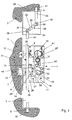
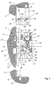
- Fig. 1 to 4 show a security lock 1 according to an exemplary embodiment of the invention, which is embedded in a door leaf 2 mounted in a frame 3.
- This security lock 1 comprises a main dead bolt 4 and a locking linkage 5 cooperating with this main deadbolt 4.
- the linkage 5 has free ends, which form auxiliary bolts 8, 9 projecting from the edge of the door leaf 2 and penetrating into mortises corresponding 10, 11, which are provided above and below the door leaf 2.
- the lock linkage 5 cooperates directly or indirectly with the main deadbolt 4 so as to automatically occupy a locking position at the moment when this main deadbolt 4 is brought into its locking position.
- Control means are provided for bringing the main deadbolt 4 into an open position and a lock position.
- These control means advantageously comprise a control plate 14 cooperating, on the one hand, with the main dead bolt 4 and, on the other hand, with the locking linkage 5.
- This control plate 14 is guided on fixed nipples 15 and 16. These are mounted on a support plate 17 and housed in mortises 18 and 19 formed in the plate 14. These mortises 18 and 19 are parallel to each other and extend perpendicular to the direction for moving the main dead bolt 4, which is indicated by the arrow 20. In this way, the plate 14 can be reciprocated in the direction of the arrow 21.
- the main dead bolt 4 has, on its end opposite to that intended to engage in the mortise 7, a pin 22 guided in an oblique mortise 23 of the control plate 14.
- the direction of inclination of the mortise 23 relative to the direction of movement 20 of the main dead bolt 4 is such that, if the plate 14 is moved upwards by an actuating means, such as a key or an electric motor 40, the main dead bolt 4 is removed in its open position.
- a return means for example a leaf spring 24, is associated with the main deadbolt 4 so as to bring the latter automatically and without external energy into its locking position when the door leaf 2 is in its position. closed position.
- the main dead bolt 4 drives the plate 14 downwards, which causes the linkage 5 in its locking position.
- the lock 1 further comprises control means for detecting the position of the lock 1 relative to the frame 3 in which the door leaf 2 is mounted, or in other words, the open position or the closing of the door 2.
- these control means comprise a pusher 13, which protrudes from the lock in the open position of the door and is pressed into the lock in the closed position. Door.
- the pusher 13 protrudes from the lock, it blocks the control plate 14 in the high position.
- the pusher 13 is depressed, it unlocks the control plate 14 and allows the spring 24 to bring the main dead bolt 4 into its locking position while driving, through the stud 22, the control member 14 to its low position as described above.
- the pusher 13 cooperates with the control means of the main dead bolt 4 so that the main dead bolt 4 is automatically brought, under the effect of the return spring 24, in its locking position as soon as the closed position of the door is detected.
- the locking linkage 5 comprises a first locking rod 26 articulated on a stud 27 of the control member 14 via a fastening flange 28.
- a second locking rod 29 is connected to the first locking rod 26 by means of a motion inverter 30.
- the first locking rod 26, which extends parallel to the side edge of the door leaf 2 moves with the control member 14 between a high position, in which the main dead bolt 4 is in its open position, and a low position, in which the main dead bolt 4 is in its closed position.
- the lower end of the first locking rod 26 forms the auxiliary dead bolt 8 which engages in the lower mortise 10.
- the upper end 31 of the first locking rod 26 cooperates with the reverser 30.
- This inverter movement comprises a lever 32 which pivots in its center around a fixed point 33 and which has, at each of its ends, an axial mortise 34 and 35.
- a pin 36 provided on the upper end 31 of the first Locking rod 26 engages in the mortise 34.
- a pin 37 provided on the lower end of the second locking rod 29 engages in the mortise 35.
- Fig. 1 shows the low position of the control part with the main dead bolt 4 in its locking position and the linkage 5 in the locking position.
- the lock 1 advantageously comprises a throwing bolt 12, which is locked in a protruding position by an arm 25 of the control part 14, when the latter is in its low position.
- Fig. 2 shows the door leaf 2 in a closed position with the lock in the open position, i.e. the main dead bolt 4 in a retracted or open position, the linkage 5 in an unlocked position and the bolt throwing 12 into an unblocked position.
- a spring not shown in FIG. 2, moves the pusher 13 in the direction of the frame 3, so that it is brought into a protruding position when opening the door.
- a lug 43 which is provided on the inner part of the pusher 13, acts against a stop 44 of the control plate 14 and holds the latter in its upper position as shown in FIG. 4.
- To open the door it suffices, therefore, to make a pushing force on the door leaf or actuate a handle, not shown.
- the electric motor 40 may be a conventional motor. It actuates a toothed wheel 41 provided, near its periphery, with a stop 42. The latter can act on the control plate 14 and bring it from its lower position to its upper position, thus unlocking the main dead bolt 4 and the locking linkage 5. It will be appreciated that the energy required for the automatic locking of the lock 1 in the closed position of the door 2 is stored in the return spring 24 when the lock 1 is opened to the using the electric motor 40, respectively with a wrench.
- Fig. 3 shows an intermediate state of the lock 1 when opening the door. If we compare this position with that of FIG. 2, we see that the bolt 12 thrown out of his mortise but still leans against the frame 3. In fact, in this FIG. 3, the door leaf 2 occupies an intermediate position between the closed position and the open position.
- Fig. 4 shows the state of the lock 1 when the door is fully open.
- the throwing bolt 12 and the pusher 13 no longer rest against the frame 3, but are completely free and are pushed by springs (not shown) in their protruding position.
- the lug 43 provided on the inner part of the pusher 13 acts against the stop 44 of the control plate 14 and maintains the latter in its upper position.
- the main dead bolt 4 and the locking linkage 5 are held in their unlocked unlocked positions.
- the pusher 13 comes into contact with the frame 3, which then pushes it inwards by releasing the stop 44 and, consequently, also the control plate 14.
- the return spring 24 acts on the main dead bolt 4 and brings it to its locking position.
- the stud 22 drives the control plate 14 to the down position by locking the linkage 5 in its locking position, as shown in FIG. 1.
- the locking linkage 5 can be mounted directly on the main dead bolt 4, for example on the stud 22.
- the control means for detecting the position of the door leaf relative to the door frame could also be include electrical detectors.
Landscapes
- Engineering & Computer Science (AREA)
- Mechanical Engineering (AREA)
- Structural Engineering (AREA)
- Lock And Its Accessories (AREA)
- Control Of Vending Devices And Auxiliary Devices For Vending Devices (AREA)
- Power-Operated Mechanisms For Wings (AREA)
- Emergency Alarm Devices (AREA)
- Train Traffic Observation, Control, And Security (AREA)
- Electrotherapy Devices (AREA)
Claims (9)
- Türblatt mit einem automatischen Sicherheitsverriegelungssystem mit:einem Hauptschlossriegel (4), der bei geschlossener Stellung der Tür (2) in eine Aufnahme in einem anliegenden Element greifen kann, um eine Verriegelungsstellung zu definieren;Kontrollmitteln (13), die geeignet sind, die geschlossene Stellung der Tür (2) zu erfassen undMitteln (14, 24, 41) zum Antrieb des Hauptschlossriegels (4), welche durch die Kontrollmittel (13) gesteuert werden und derart mit dem Schlossriegel (4) verbunden sind, dass dieser bei Erfassung der geschlossenen Stellung der Tür (2) durch die Kontrollmittel (13) automatisch in seine Verriegelungsstellung gebracht werden kann;einem ersten Verriegelungsstift (26) und einem zweiten Verriegelungsstift (29), wobei jeder dieser beiden Verriegelungsstifte (26, 29) so montiert ist, dass er in einer senkrecht zu der Verriegelungsrichtung des Hauptschlossriegels (4) verlaufenden Richtung gleiten kann,wobei die Mittel (14, 24, 41) zum Antrieb des Hauptschlossriegels (4) derart mit dem ersten Verriegelungsstift (26) verbunden sind, dass dieser bei Erfassung der geschlossenen Stellung der Tür (2) durch die Kontrollmittel (13) durch eine Translation in einer ersten Richtung automatisch in eine Verriegelungsstellung gebracht werden kann undeinem Bewegungsumkehrer (30), welcher derart zwischen dem ersten Verriegelungsstift (26) und dem zweiten Verriegelungsstift (29) verbunden ist, dass der Letztere durch eine Translation in einer zu der ersten Richtung entgegengesetzten Richtung automatisch in eine Verriegelungsstellung gebracht wird,dadurch gekennzeichnet, dassder Hauptschlossriegel (4), die Antriebsmittel (14, 24, 41) und die Kontrollmittel (13) zu einer Schlosseinheit gehören, die in dem Türblatt (2) mit einem gewissen Abstand zu einem ersten horizontalen Rand und einem zweiten horizontalen Rand des Türblatts (2) eingebaut ist;der Bewegungsumkehrer (30) eine getrennte Einheit bildet, die in der Nähe des ersten horizontalen Rands des Türblatts (2) angeordnet ist;der erste Verriegelungsstift (26) die Schlosseinheit durchquert, wo er mit den Antriebsmitteln verbunden ist, und sich im Inneren des Türblatts zwischen den zwei horizontalen Rändern des Türblatts erstreckt, wobei ein erstes Ende des ersten Verriegelungsstifts (26) mit dem Bewegungsumkehrer (30) in der getrennten Einheit nahe des ersten horizontalen Randes verbunden ist und ein zweites freies Ende des ersten Verriegelungsstifts (26) in dem zweiten horizontalen Rand einen ersten Nebenschlossriegel (8) bildet undder zweite Verriegelungsstift (29) ein freies Ende umfasst, welches in dem ersten horizontalen Rand des Türblatts (2) einen zweiten Nebenschlossriegel (9) bildet.
- Türblatt nach Anspruch 1, dadurch gekennzeichnet, dass
die Mittel zum Antrieb des Hauptschlossriegels (4) eine Rückstellfeder (24) umfassen, welche geeignet ist, den Hauptschlossriegel (4) in seine Verriegelungsstellung zu bringen und
die Kontrollmittel (13) ein Blockiermittel (43, 44) umfassen, das geeignet ist, bei Erfassung einer geöffneten Stellung der Tür (2) den Hauptschlossriegel (4) in Öffnungsstellung zu blockieren und bei Erfassung einer geschlossenen Stellung der Tür (2) den Hauptschlossriegel (4) freizugeben. - Türblatt nach Anspruch 1 oder 2, dadurch gekennzeichnet, dass die Antriebsmittel eine Antriebsplatte (14) umfassen, wobei diese Antriebsplatte (14) derart in der Schlosseinheit (1) montiert ist, dass sie eine Translationsbewegung in einer parallel zu der Verschieberichtung des Hauptschlossriegels (4) verlaufenden Ebene erfahren kann und einerseits mit dem Hauptschlossriegel (4) und andererseits mit dem ersten Verriegelungsstift (26) zusammenwirkt, um gleichzeitig den Hauptschlossriegel (4) und den ersten Verriegelungsstift (26) in ihre jeweilige Verriegelungsstellung mitzunehmen.
- Türblatt nach Anspruch 3, dadurch gekennzeichnet, dass die Antriebsplatte (14) derart in der Schlosseinheit (1) montiert ist, dass sie eine Translationsbewegung in einer weitestgehend senkrecht zu der Verschieberichtung des Hauptschlossriegels (4) verlaufenden Richtung erfahren kann.
- Türblatt nach einem der Ansprüche 3 oder 4, dadurch gekennzeichnet, dass die Antriebsplatte (14) derart mit einem Schnapper (12) zusammenwirkt, dass der Letztere in einer Verriegelungsstellung blockiert wird, wenn der Hauptschlossriegel (4) sich ebenfalls in seiner Verriegelungsstellung befindet.
- Türblatt nach Anspruch 3, dadurch gekennzeichnet, dass der erste Verriegelungsstift (26) an der Antriebsplatte (14) angelenkt ist.
- Türblatt nach einem der Ansprüche 1 bis 6, dadurch gekennzeichnet, dass der Bewegungsumkehrer (30) einen Hebel (32) umfasst, welcher in seinem Zentrum um einen Fixpunkt (33) schwenkt und an jedem seiner Enden eine axiale Aufnahme (34, 35) zur Aufnahme eines Zapfens (36, 37) eines der beiden Verriegelungsstifte (26, 29) aufweist.
- Türblatt nach einem der Ansprüche 1 bis 7, dadurch gekennzeichnet, dass die Kontrollmittel einen Drücker (13) und eine Feder umfassen, die den Drücker (13) beim Öffnen der Tür (2) in eine vorspringende Stellung bringt.
- Türblatt nach Anspruch 8, dadurch gekennzeichnet, dass der Drücker (13) sich in einer eingezogenen Stellung befindet, wenn der Hauptschlossriegel (4) sich in seiner Verriegelungsstellung befindet, und sich in einer vorspringenden Stellung befindet, wenn der Hauptschlossriegel (4) sich in seiner Öffnungsstellung befindet.
Applications Claiming Priority (2)
| Application Number | Priority Date | Filing Date | Title |
|---|---|---|---|
| LU90671A LU90671B1 (fr) | 2000-11-06 | 2000-11-06 | Serrure de s-curit- - plusieurs points de verrouillage |
| LU90671 | 2000-11-06 |
Publications (2)
| Publication Number | Publication Date |
|---|---|
| EP1203860A1 EP1203860A1 (de) | 2002-05-08 |
| EP1203860B1 true EP1203860B1 (de) | 2006-04-19 |
Family
ID=19731944
Family Applications (1)
| Application Number | Title | Priority Date | Filing Date |
|---|---|---|---|
| EP01126287A Expired - Lifetime EP1203860B1 (de) | 2000-11-06 | 2001-11-06 | Türblatt mit automatischem Sicherheitsverriegelungssystem |
Country Status (4)
| Country | Link |
|---|---|
| EP (1) | EP1203860B1 (de) |
| AT (1) | ATE323814T1 (de) |
| DE (2) | DE1203860T1 (de) |
| LU (1) | LU90671B1 (de) |
Families Citing this family (12)
| Publication number | Priority date | Publication date | Assignee | Title |
|---|---|---|---|---|
| DE10359804A1 (de) * | 2003-12-19 | 2005-07-14 | Aug. Winkhaus Gmbh & Co. Kg | Antriebseinrichtung für einen Treibstangenbeschlag |
| DE102006001003A1 (de) * | 2006-01-05 | 2007-07-12 | Dorma Gmbh + Co. Kg | Elektromechanisches Türschloss |
| WO2009060483A1 (en) * | 2007-11-07 | 2009-05-14 | Assa Abloy Italia S.P.A. | Lock |
| DE202012007383U1 (de) * | 2012-08-01 | 2012-09-05 | Eldomat Innovative Sicherheit Gmbh | Selbstverriegelnde Schließvorrichtung mit einem Mehrfachverriegelungsantrieb |
| DE102013112380A1 (de) * | 2013-11-11 | 2015-05-13 | Dorma Deutschland Gmbh | Gangreserve für ein motorbetriebenes Schloss |
| CN107227901B (zh) * | 2017-06-30 | 2023-03-28 | 江西技德科技有限公司 | 一种转轴副锁装置 |
| CN107654153A (zh) * | 2017-10-28 | 2018-02-02 | 宋运恒 | 防盗开门机器人 |
| ES2899582T3 (es) * | 2017-11-08 | 2022-03-14 | Eldomat Innovative Sicherheit Gmbh | Dispositivo de cierre automático con accionamiento de cierre múltiple II |
| WO2019091594A1 (de) * | 2017-11-08 | 2019-05-16 | Eldomat Innovative Sicherheit Gmbh | Selbstverriegelnde schliessvorrichtung mit mehrfachverriegelungsantrieb |
| DE102018106832A1 (de) * | 2018-03-22 | 2019-09-26 | Dormakaba Deutschland Gmbh | Gegenschloss für eine Standflügeltür |
| US11851925B2 (en) * | 2019-02-27 | 2023-12-26 | Sargent Manufacturing Company | Key override for electromechanical multi-point latching device |
| FR3097581B1 (fr) | 2019-06-18 | 2024-07-12 | Etablissements Devismes | Boitier de serrure à verrouillage automatique |
Family Cites Families (6)
| Publication number | Priority date | Publication date | Assignee | Title |
|---|---|---|---|---|
| US1420910A (en) * | 1920-05-17 | 1922-06-27 | Arthur R Collier | Locking device |
| GB470433A (en) * | 1936-06-17 | 1937-08-16 | John Magnus Ragnar Ring | Improvements in or relating to espagnolette fastenings |
| FR2512097B1 (fr) * | 1981-08-28 | 1986-01-24 | Bouvet Jean Claude | Ensemble de serrure de securite pour porte ou analogue |
| FI83802C (fi) * | 1988-11-25 | 1991-08-26 | Abloy Security Ltd Oy | Elektromekaniskt doerrlaos. |
| ES2115191T3 (es) * | 1994-02-21 | 1998-06-16 | Hellmuller & Zingg Ag | Cerradura de puerta. |
| FR2725470A1 (fr) * | 1994-10-05 | 1996-04-12 | Rochman Henri | Dispositif de serrure a verrouillage et a condamnation automatiques et a deverrouillage assiste |
-
2000
- 2000-11-06 LU LU90671A patent/LU90671B1/fr active
-
2001
- 2001-11-06 EP EP01126287A patent/EP1203860B1/de not_active Expired - Lifetime
- 2001-11-06 DE DE1203860T patent/DE1203860T1/de active Pending
- 2001-11-06 AT AT01126287T patent/ATE323814T1/de not_active IP Right Cessation
- 2001-11-06 DE DE60118862T patent/DE60118862T2/de not_active Expired - Lifetime
Also Published As
| Publication number | Publication date |
|---|---|
| EP1203860A1 (de) | 2002-05-08 |
| DE1203860T1 (de) | 2002-11-14 |
| ATE323814T1 (de) | 2006-05-15 |
| DE60118862D1 (de) | 2006-05-24 |
| DE60118862T2 (de) | 2006-10-12 |
| LU90671B1 (fr) | 2002-05-07 |
Similar Documents
| Publication | Publication Date | Title |
|---|---|---|
| EP1203860B1 (de) | Türblatt mit automatischem Sicherheitsverriegelungssystem | |
| EP0509932B1 (de) | Verriegelungsvorrichtung für einen Behälter mit Deckel und Behälter mit einer solchen Vorrichtung | |
| EP0341173B1 (de) | Treibstangenverschluss für Türen, Fenster o.dgl. | |
| FR2789717A1 (fr) | Serrure en trois parties, pour ouvrant de vehicule automobile | |
| EP1030012B1 (de) | Kraftfahrzeugschloss mit energiespeichernder Entriegelungsvorrichtung | |
| FR2619150A1 (fr) | Serrrure de porte | |
| FR2504180A1 (fr) | Serrure a pene dormant | |
| EP2348171A1 (de) | Blockiervorrichtung eines Strukturelements gegen eine benachbarte Struktur, mit dieser Vorrichtung ausgestattetes Luftfahrzeug und mit dieser Vorrichtung umgesetztes Extraktionsverfahren | |
| FR2775717A1 (fr) | Dispositif d'ouverture/fermeture d'un ouvrant, notamment pour vehicule automobile | |
| FR2656362A1 (fr) | Verrou a pene dormant a verrouillage automatique selectif. | |
| EP0629760A1 (de) | Schloss für Fenster- oder ähnlichen Schliebeflügeln | |
| EP3564467A1 (de) | Schliesssystem mit mechanischer verriegelung | |
| EP0312654B1 (de) | Sicherheitsschloss | |
| FR2488318A1 (fr) | Serrure a larder du type trois points | |
| FR2529937A1 (fr) | Dispositif de fermeture a pene profile enveloppant rotatif et a gache rentrante | |
| EP0305485A1 (de) | Schloss mit elektromagnetischer verriegelung/entriegelung. | |
| EP0029405B1 (de) | Treibstangengetriebe, insbesondere Treibstangenschlossgetriebe für Türen, Fenstertüren od. dgl. | |
| EP1857618A1 (de) | Tür, die eine Öffnung eines Innenraums verschließen kann, der mindestens ein bewegliches und potenziell gefährliches Element, insbesondere einen Antrieb, enthält | |
| EP0294276B1 (de) | Kombinationsschloss mit Sperrscheiben und automatischer Löschung der Kombination beim Schliessen | |
| FR2871509A1 (fr) | Portillon pour barriere de protection de piscine | |
| EP0360696A1 (de) | Verriegelungsvorrichtung für eine zweiflügelige Tür | |
| FR2601062A1 (fr) | Loquet de verrouillage a pene pivotant, destine notamment a une partie comportant une fermeture antipanique. | |
| FR2789718A1 (fr) | Serrure a condamnation enfant, pour ouvrant de vehicule automobile | |
| FR2493896A1 (fr) | Serrure de porte a sens de montage indifferent | |
| EP0424288B1 (de) | Türverriegelung und Türrahmen mit solcher Verriegelung |
Legal Events
| Date | Code | Title | Description |
|---|---|---|---|
| PUAI | Public reference made under article 153(3) epc to a published international application that has entered the european phase |
Free format text: ORIGINAL CODE: 0009012 |
|
| AK | Designated contracting states |
Kind code of ref document: A1 Designated state(s): AT BE CH CY DE DK ES FI FR GB GR IE IT LI LU MC NL PT SE TR |
|
| AX | Request for extension of the european patent |
Free format text: AL;LT;LV;MK;RO;SI |
|
| DET | De: translation of patent claims | ||
| 17P | Request for examination filed |
Effective date: 20021106 |
|
| AKX | Designation fees paid |
Designated state(s): AT BE CH CY DE DK ES FI FR GB GR IE IT LI LU MC NL PT SE TR |
|
| 17Q | First examination report despatched |
Effective date: 20030526 |
|
| GRAP | Despatch of communication of intention to grant a patent |
Free format text: ORIGINAL CODE: EPIDOSNIGR1 |
|
| RTI1 | Title (correction) |
Free format text: DOOR LEAF WITH AUTOMATIC SECURITY LOCKING SYSTEM |
|
| RAP1 | Party data changed (applicant data changed or rights of an application transferred) |
Owner name: MULTIMET S.A. |
|
| GRAS | Grant fee paid |
Free format text: ORIGINAL CODE: EPIDOSNIGR3 |
|
| GRAA | (expected) grant |
Free format text: ORIGINAL CODE: 0009210 |
|
| AK | Designated contracting states |
Kind code of ref document: B1 Designated state(s): AT BE CH CY DE DK ES FI FR GB GR IE IT LI LU MC NL PT SE TR |
|
| PG25 | Lapsed in a contracting state [announced via postgrant information from national office to epo] |
Ref country code: IT Free format text: LAPSE BECAUSE OF FAILURE TO SUBMIT A TRANSLATION OF THE DESCRIPTION OR TO PAY THE FEE WITHIN THE PRESCRIBED TIME-LIMIT;WARNING: LAPSES OF ITALIAN PATENTS WITH EFFECTIVE DATE BEFORE 2007 MAY HAVE OCCURRED AT ANY TIME BEFORE 2007. THE CORRECT EFFECTIVE DATE MAY BE DIFFERENT FROM THE ONE RECORDED. Effective date: 20060419 Ref country code: FI Free format text: LAPSE BECAUSE OF FAILURE TO SUBMIT A TRANSLATION OF THE DESCRIPTION OR TO PAY THE FEE WITHIN THE PRESCRIBED TIME-LIMIT Effective date: 20060419 Ref country code: AT Free format text: LAPSE BECAUSE OF FAILURE TO SUBMIT A TRANSLATION OF THE DESCRIPTION OR TO PAY THE FEE WITHIN THE PRESCRIBED TIME-LIMIT Effective date: 20060419 Ref country code: IE Free format text: LAPSE BECAUSE OF FAILURE TO SUBMIT A TRANSLATION OF THE DESCRIPTION OR TO PAY THE FEE WITHIN THE PRESCRIBED TIME-LIMIT Effective date: 20060419 Ref country code: NL Free format text: LAPSE BECAUSE OF FAILURE TO SUBMIT A TRANSLATION OF THE DESCRIPTION OR TO PAY THE FEE WITHIN THE PRESCRIBED TIME-LIMIT Effective date: 20060419 |
|
| REG | Reference to a national code |
Ref country code: GB Ref legal event code: FG4D Free format text: NOT ENGLISH |
|
| REF | Corresponds to: |
Ref document number: 60118862 Country of ref document: DE Date of ref document: 20060524 Kind code of ref document: P |
|
| REG | Reference to a national code |
Ref country code: IE Ref legal event code: FG4D Free format text: LANGUAGE OF EP DOCUMENT: FRENCH |
|
| GBT | Gb: translation of ep patent filed (gb section 77(6)(a)/1977) |
Effective date: 20060524 |
|
| PG25 | Lapsed in a contracting state [announced via postgrant information from national office to epo] |
Ref country code: DK Free format text: LAPSE BECAUSE OF FAILURE TO SUBMIT A TRANSLATION OF THE DESCRIPTION OR TO PAY THE FEE WITHIN THE PRESCRIBED TIME-LIMIT Effective date: 20060719 Ref country code: SE Free format text: LAPSE BECAUSE OF FAILURE TO SUBMIT A TRANSLATION OF THE DESCRIPTION OR TO PAY THE FEE WITHIN THE PRESCRIBED TIME-LIMIT Effective date: 20060719 |
|
| PG25 | Lapsed in a contracting state [announced via postgrant information from national office to epo] |
Ref country code: ES Free format text: LAPSE BECAUSE OF FAILURE TO SUBMIT A TRANSLATION OF THE DESCRIPTION OR TO PAY THE FEE WITHIN THE PRESCRIBED TIME-LIMIT Effective date: 20060730 |
|
| PG25 | Lapsed in a contracting state [announced via postgrant information from national office to epo] |
Ref country code: PT Free format text: LAPSE BECAUSE OF FAILURE TO SUBMIT A TRANSLATION OF THE DESCRIPTION OR TO PAY THE FEE WITHIN THE PRESCRIBED TIME-LIMIT Effective date: 20060919 |
|
| NLV1 | Nl: lapsed or annulled due to failure to fulfill the requirements of art. 29p and 29m of the patents act | ||
| REG | Reference to a national code |
Ref country code: IE Ref legal event code: FD4D |
|
| PG25 | Lapsed in a contracting state [announced via postgrant information from national office to epo] |
Ref country code: MC Free format text: LAPSE BECAUSE OF NON-PAYMENT OF DUE FEES Effective date: 20061130 Ref country code: LI Free format text: LAPSE BECAUSE OF NON-PAYMENT OF DUE FEES Effective date: 20061130 Ref country code: CH Free format text: LAPSE BECAUSE OF NON-PAYMENT OF DUE FEES Effective date: 20061130 |
|
| PLBE | No opposition filed within time limit |
Free format text: ORIGINAL CODE: 0009261 |
|
| STAA | Information on the status of an ep patent application or granted ep patent |
Free format text: STATUS: NO OPPOSITION FILED WITHIN TIME LIMIT |
|
| 26N | No opposition filed |
Effective date: 20070122 |
|
| REG | Reference to a national code |
Ref country code: CH Ref legal event code: PL |
|
| BECA | Be: change of holder's address |
Owner name: S.A. HEINENRUE DERRIERE-L'EAU 11, B-4960 MALMEDY Effective date: 20070130 Owner name: S.A. HEINENRUE DERRIERE-L'EAU 11, B-4960 MALMEDY Effective date: 20060419 |
|
| BECH | Be: change of holder |
Owner name: S.A. HEINENRUE DERRIERE-L'EAU 11, B-4960 MALMEDY Effective date: 20070130 Owner name: S.A. HEINEN Effective date: 20060419 |
|
| REG | Reference to a national code |
Ref country code: GB Ref legal event code: 732E |
|
| REG | Reference to a national code |
Ref country code: FR Ref legal event code: TP |
|
| PG25 | Lapsed in a contracting state [announced via postgrant information from national office to epo] |
Ref country code: GR Free format text: LAPSE BECAUSE OF FAILURE TO SUBMIT A TRANSLATION OF THE DESCRIPTION OR TO PAY THE FEE WITHIN THE PRESCRIBED TIME-LIMIT Effective date: 20060720 |
|
| PG25 | Lapsed in a contracting state [announced via postgrant information from national office to epo] |
Ref country code: LU Free format text: LAPSE BECAUSE OF NON-PAYMENT OF DUE FEES Effective date: 20061106 Ref country code: TR Free format text: LAPSE BECAUSE OF FAILURE TO SUBMIT A TRANSLATION OF THE DESCRIPTION OR TO PAY THE FEE WITHIN THE PRESCRIBED TIME-LIMIT Effective date: 20060419 |
|
| PG25 | Lapsed in a contracting state [announced via postgrant information from national office to epo] |
Ref country code: CY Free format text: LAPSE BECAUSE OF FAILURE TO SUBMIT A TRANSLATION OF THE DESCRIPTION OR TO PAY THE FEE WITHIN THE PRESCRIBED TIME-LIMIT Effective date: 20060419 |
|
| REG | Reference to a national code |
Ref country code: FR Ref legal event code: PLFP Year of fee payment: 15 |
|
| REG | Reference to a national code |
Ref country code: FR Ref legal event code: PLFP Year of fee payment: 16 |
|
| REG | Reference to a national code |
Ref country code: FR Ref legal event code: PLFP Year of fee payment: 17 |
|
| PGFP | Annual fee paid to national office [announced via postgrant information from national office to epo] |
Ref country code: FR Payment date: 20201126 Year of fee payment: 20 Ref country code: DE Payment date: 20201126 Year of fee payment: 20 Ref country code: GB Payment date: 20201006 Year of fee payment: 20 |
|
| PGFP | Annual fee paid to national office [announced via postgrant information from national office to epo] |
Ref country code: BE Payment date: 20201030 Year of fee payment: 20 |
|
| REG | Reference to a national code |
Ref country code: DE Ref legal event code: R071 Ref document number: 60118862 Country of ref document: DE |
|
| REG | Reference to a national code |
Ref country code: GB Ref legal event code: PE20 Expiry date: 20211105 |
|
| REG | Reference to a national code |
Ref country code: BE Ref legal event code: MK Effective date: 20211106 |
|
| PG25 | Lapsed in a contracting state [announced via postgrant information from national office to epo] |
Ref country code: GB Free format text: LAPSE BECAUSE OF EXPIRATION OF PROTECTION Effective date: 20211105 |