EP1203885B1 - Pompe à engrenages - Google Patents
Pompe à engrenages Download PDFInfo
- Publication number
- EP1203885B1 EP1203885B1 EP01126024A EP01126024A EP1203885B1 EP 1203885 B1 EP1203885 B1 EP 1203885B1 EP 01126024 A EP01126024 A EP 01126024A EP 01126024 A EP01126024 A EP 01126024A EP 1203885 B1 EP1203885 B1 EP 1203885B1
- Authority
- EP
- European Patent Office
- Prior art keywords
- bearing
- gear pump
- pump according
- intermediate plate
- cover
- Prior art date
- Legal status (The legal status is an assumption and is not a legal conclusion. Google has not performed a legal analysis and makes no representation as to the accuracy of the status listed.)
- Expired - Lifetime
Links
Images



Classifications
-
- F—MECHANICAL ENGINEERING; LIGHTING; HEATING; WEAPONS; BLASTING
- F04—POSITIVE - DISPLACEMENT MACHINES FOR LIQUIDS; PUMPS FOR LIQUIDS OR ELASTIC FLUIDS
- F04C—ROTARY-PISTON, OR OSCILLATING-PISTON, POSITIVE-DISPLACEMENT MACHINES FOR LIQUIDS; ROTARY-PISTON, OR OSCILLATING-PISTON, POSITIVE-DISPLACEMENT PUMPS
- F04C15/00—Component parts, details or accessories of machines, pumps or pumping installations, not provided for in groups F04C2/00 - F04C14/00
- F04C15/0088—Lubrication
-
- F—MECHANICAL ENGINEERING; LIGHTING; HEATING; WEAPONS; BLASTING
- F04—POSITIVE - DISPLACEMENT MACHINES FOR LIQUIDS; PUMPS FOR LIQUIDS OR ELASTIC FLUIDS
- F04C—ROTARY-PISTON, OR OSCILLATING-PISTON, POSITIVE-DISPLACEMENT MACHINES FOR LIQUIDS; ROTARY-PISTON, OR OSCILLATING-PISTON, POSITIVE-DISPLACEMENT PUMPS
- F04C13/00—Adaptations of machines or pumps for special use, e.g. for extremely high pressures
- F04C13/001—Pumps for particular liquids
- F04C13/002—Pumps for particular liquids for homogeneous viscous liquids
-
- F—MECHANICAL ENGINEERING; LIGHTING; HEATING; WEAPONS; BLASTING
- F04—POSITIVE - DISPLACEMENT MACHINES FOR LIQUIDS; PUMPS FOR LIQUIDS OR ELASTIC FLUIDS
- F04C—ROTARY-PISTON, OR OSCILLATING-PISTON, POSITIVE-DISPLACEMENT MACHINES FOR LIQUIDS; ROTARY-PISTON, OR OSCILLATING-PISTON, POSITIVE-DISPLACEMENT PUMPS
- F04C15/00—Component parts, details or accessories of machines, pumps or pumping installations, not provided for in groups F04C2/00 - F04C14/00
- F04C15/0003—Sealing arrangements in rotary-piston machines or pumps
- F04C15/0034—Sealing arrangements in rotary-piston machines or pumps for other than the working fluid, i.e. the sealing arrangements are not between working chambers of the machine
- F04C15/0038—Shaft sealings specially adapted for rotary-piston machines or pumps
-
- F—MECHANICAL ENGINEERING; LIGHTING; HEATING; WEAPONS; BLASTING
- F04—POSITIVE - DISPLACEMENT MACHINES FOR LIQUIDS; PUMPS FOR LIQUIDS OR ELASTIC FLUIDS
- F04C—ROTARY-PISTON, OR OSCILLATING-PISTON, POSITIVE-DISPLACEMENT MACHINES FOR LIQUIDS; ROTARY-PISTON, OR OSCILLATING-PISTON, POSITIVE-DISPLACEMENT PUMPS
- F04C15/00—Component parts, details or accessories of machines, pumps or pumping installations, not provided for in groups F04C2/00 - F04C14/00
- F04C15/0096—Heating; Cooling
-
- F—MECHANICAL ENGINEERING; LIGHTING; HEATING; WEAPONS; BLASTING
- F04—POSITIVE - DISPLACEMENT MACHINES FOR LIQUIDS; PUMPS FOR LIQUIDS OR ELASTIC FLUIDS
- F04C—ROTARY-PISTON, OR OSCILLATING-PISTON, POSITIVE-DISPLACEMENT MACHINES FOR LIQUIDS; ROTARY-PISTON, OR OSCILLATING-PISTON, POSITIVE-DISPLACEMENT PUMPS
- F04C2/00—Rotary-piston machines or pumps
- F04C2/08—Rotary-piston machines or pumps of intermeshing-engagement type, i.e. with engagement of co-operating members similar to that of toothed gearing
- F04C2/082—Details specially related to intermeshing engagement type machines or pumps
- F04C2/086—Carter
-
- F—MECHANICAL ENGINEERING; LIGHTING; HEATING; WEAPONS; BLASTING
- F04—POSITIVE - DISPLACEMENT MACHINES FOR LIQUIDS; PUMPS FOR LIQUIDS OR ELASTIC FLUIDS
- F04C—ROTARY-PISTON, OR OSCILLATING-PISTON, POSITIVE-DISPLACEMENT MACHINES FOR LIQUIDS; ROTARY-PISTON, OR OSCILLATING-PISTON, POSITIVE-DISPLACEMENT PUMPS
- F04C2/00—Rotary-piston machines or pumps
- F04C2/08—Rotary-piston machines or pumps of intermeshing-engagement type, i.e. with engagement of co-operating members similar to that of toothed gearing
- F04C2/12—Rotary-piston machines or pumps of intermeshing-engagement type, i.e. with engagement of co-operating members similar to that of toothed gearing of other than internal-axis type
- F04C2/14—Rotary-piston machines or pumps of intermeshing-engagement type, i.e. with engagement of co-operating members similar to that of toothed gearing of other than internal-axis type with toothed rotary pistons
- F04C2/18—Rotary-piston machines or pumps of intermeshing-engagement type, i.e. with engagement of co-operating members similar to that of toothed gearing of other than internal-axis type with toothed rotary pistons with similar tooth forms
-
- Y—GENERAL TAGGING OF NEW TECHNOLOGICAL DEVELOPMENTS; GENERAL TAGGING OF CROSS-SECTIONAL TECHNOLOGIES SPANNING OVER SEVERAL SECTIONS OF THE IPC; TECHNICAL SUBJECTS COVERED BY FORMER USPC CROSS-REFERENCE ART COLLECTIONS [XRACs] AND DIGESTS
- Y10—TECHNICAL SUBJECTS COVERED BY FORMER USPC
- Y10S—TECHNICAL SUBJECTS COVERED BY FORMER USPC CROSS-REFERENCE ART COLLECTIONS [XRACs] AND DIGESTS
- Y10S384/00—Bearings
- Y10S384/90—Cooling or heating
Definitions
- the present invention relates to a gear pump for carrying high viscous fluid such as molten resins.
- the gear pump for carrying molten resins has a pair of gear rotors, that being supported rotatably the pump body through a bearing.
- the bearing is a slide bearing, which is of a self- lubricating type in which a part of the molten resins to be carried as bearing lubricating agent.
- Methods for cooling the lubricant include a method for cooling a rotor shaft (for example, see U.S. Patent 5,292,237), a method for cooling a bearing (for example, see U.S. Patent 5,924,854), or a method for cooling a bearing (for example, see Japanese Patent Application Laid-Open No. Hei 10-141247 Publication).
- the bearing since the bearing is pressed in a different direction depending on the operating conditions such as the discharge pressure or the number of revolutions, it is preferable that the bearing be mounted in the free state with respect to the body. However, when it is secured to the body as in the prior art described previously, there occurs a problem that the unreasonable load is applied to the bearing.
- the aforementioned integral type has a problem that manufacturing is difficult and the cost increases.
- an inlet passage or an outlet passage of cooling medium with respect to the bearing are provided on a cover (side plate) for securing the bearing, and a seal construction between the cover and the bearing is difficult.
- the present invention employs the following constitutions.
- a gear pump comprising: a body; a bearing; a pair of gear rotors, said gear rotors being supported on said body through said bearing; a cover for preventing said bearing from being slipped out in the axial direction of said bearing, said cover being secured to said body; a temperature adjusting medium passage formed in said bearing; an inlet pipe provided on the axial outer end of said bearing, said inlet pipe being communicated with said temperature adjusting medium passage; an outlet pipe provided on the axial outer end of said bearing, said outlet pipe being communicated with said temperature adjusting medium passage; and an intermediate plate interposed between the axial outer end of said bearing and said cover, said intermediate plate being formed with a hole for inserting said input pipe and said outlet pipe therein, wherein said cover is provided with a guide portion having said inlet pipe and said outlet pipe loosely fitted therein to guide them to outside.
- the provision of the intermediate plate enables positive prevention of the leakage of temperature adjusting medium and the leakage of material to be carried.
- constitution of inserting them into the intermediate plate may be employed to thereby facilitate assembling.
- said bearing is held on said body in a non-secured state.
- the pump is for carrying molten resins.
- constitution is employed in which a part of the carried material to be supplied as lubricant between said bearing and said gear rotor.
- both end surfaces of said intermediate plate may comprise seal surfaces.
- both end surfaces of said intermediate plate may contact with said bearing and said cover through a seal member.
- said inlet pipe and said outlet pipe may be mounted on said bearing through watertight means.
- said intermediate plate may be integrated with a thrust plate provided in order to locate said bearing in an axial direction.
- Said thrust plate is provided separately from said bearing.
- a viscous seal for preventing leakage of liquid form said gear rotor, said viscous seal being provided at an axial outer position of said bearing, and fastening means provided on said viscous seal, said fastening means raising mounting surface pressure of said intermediate plate and said cover.
- a gear pump comprising: a body; a bearing; a pair of gear rotors, said gear rotors being supported on said body through said bearing; a cover for preventing said bearing from being slipped out in the axial direction of the bearing, said cover being secured to said body; temperature adjusting medium passage formed in said bearing; an inlet pipe provided on the axial outer end of said bearing, said inlet pipe being communicated with said temperature adjusting medium passage, at least a part of said inlet pipe being formed from a flexible member; and an outlet pipe provided on the axial outer end of said bearing, said outlet pipe being communicated with said temperature adjusting medium passage, at least a part of said outlet pipe being formed from a flexible member, wherein said cover is provided with a guide portion having said inlet pipe and said outlet pipe loosely fitted therein to guide them to outside.
- constitution can be employed in which the guide portion is provided in parallel with the shaft center of the gear rotor, and the diameter of the guide portion is larger than that of the inlet pipe and larger than that of the outlet pipe.
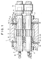
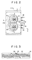
- FIGS. 1 and 2 Shown in FIGS. 1 and 2 is a gear pump for carrying quantitative molten resins in a mixing granulating system.
- the gear pump has a pump body 1, and a pair of gear rotors 2 encased in the body 1.
- the body is formed into a block form, within which a glasses-like rotor housing hole 3 is formed, and a resin inlet 4 and an outlet 5 are formed in an axial central portion of the rotor housing hole 3 and on both sides in a diametrical direction.
- the pair of gear rotors 2, 2 are rotatably housed in the rotor housing hole 3 through a bearing 6.
- the rotor 2 comprises a gear part 7 and shaft parts 8 formed on both sides of the gear part 7.
- the gear part 7 of the pair of rotors 2, 2 is always meshed, and the shaft part 8 is supported on the bearing 6.
- One end of the shaft part 8 of the rotor 2 is connected to a drive device (not shown) through a coupling 9, the rotor 2 being rotated and driven in a direction of arrow a, and molten resins are carried from the resin inlet 4 to the outlet 5 by the gear part 7.
- the bearing 6 is fitted in the rotor housing hole 3 in a non-secured state.
- the bearing 6 is formed cylindrically, an inner circumferential surface thereof being a slide bearing surface, and a part of an outer circumferential surface being cut and formed to be a flat surface.
- the bearing 6 is housed in the glasses-like rotor housing hole 3, in which state the flat surfaces come in contact with each other to prevent rotation thereof. It is noted that the outside diameter of the bearing 6 is about 600 mm in case of a large one.
- the axial inner end of the bearing 6 can be placed in contact with the side of the gear part 7 of the rotor 2.
- the axial outer end of the bearing 6 is substantially flush with the end of the body 1.
- the bearing 6 is prevented from being slipped out outward in an axial direction by a cover 11 mounted on the end of the body through an intermediate plate 10. And, a small diameter shoulder is formed on the outer circumferential portion of the axial outer end of the bearing 6, and a ring-like thrust plate 12 is fitted in the shoulder.
- thrust plate 12 may be integrated with the bearing 6.
- the intermediate plate 10 is formed from a single plate, which has a pair of through-holes 13 for loosely fitting the shaft part 8 of the gear rotor 8.
- the outer shape of the intermediate plate 10 has size for covering the whole end of the bearing 6 and a part of the end of the body 1, and the thickness of the intermediate plate 10 is about 60 mm.
- the cover 11 is a weight member formed from a block, whose outer shape is substantially the same as the intermediate plate 10, and whose thickness is about 200mm.
- the cover 11 is secured to the end of the body 1 through a bolt 14.
- the cover 11 is provided with a pair of seal member insert holes 15 which are concentric with the shaft center of the gear rotor 2, and a viscous seal 16 is fitted in the hole 15.
- the viscous seal 16 is formed into a cylindrical body with a flange, whose outer circumferential surface is partly formed with a flat surface, and a pair of viscous seals 16 have flat surfaces placed in contact with each other, similar to the bearing 6.
- the flange of the viscous seal 16 is secured to the cover 11 through a bolt 17.
- the axial inner end of the viscous seal 16 faces to the outer end of the intermediate plate 10.
- the inner circumferential surface of the viscous seal 16 and the shaft part 8 of the gear rotor 2 prevent the molten resin from flowing out by means of a labyrinth seal.
- a rotor temperature adjusting device 18 is provided on the shaft center portion of the rotor 2, and a control device (not shown) for supplying temperature adjusting medium is connected to the adjusting device 18. Since their details are the same as those described in U.S. Patent 5,292,237, reference is made thereto, and the detailed explanation thereof is omitted.
- the bearing 6 is also provided with a bearing temperature adjusting device 19, and a control device (not shown) for supplying a temperature adjusting medium is connected to the adjusting device 19.
- the bearing temperature adjusting device 19 has a temperature adjusting medium passage 20 formed internally of the bearing 6.
- the temperature adjusting medium passage 20 comprises an annular space 21 formed internally of the bearing 6, and a partitioning wall 22 provided in the annular space 21.
- FIG. 3 is a circumferential developed view of the temperature adjusting medium passage 20, and the partitioning wall 22 is provided spirally.
- the annular space 21 is formed with the temperature adjusting medium passage 20 comprising two spiral grooves, and a temperature adjusting medium inlet 23 is formed in the end of one of the grooves, and a temperature adjusting medium outlet 24 is formed in the end of the other.
- the bearing 6 is constituted by an inner circumferential member 6a and an outer circumferential member 6b connected integrally, and the temperature adjusting medium passage 20 is formed in a boundary of the inner circumferential member 6a and the outer circumferential member 6b.
- annular recess for forming the annular space 21 is formed in the outer circumferential surface of the inner circumferential member 6a, and the spiral partitioning wall 22 shown in FIG. 3 is formed integrally within the annular recess. And, the outer circumferential member 6b is fitted in the inner circumferential member 6a to form an integral configuration. This integral configuration is done welding or welding after shrinkage fitting.
- the outer circumferential surface of the partitioning wall 22 is in contact with the inner circumferential surface of the outer circumferential member 6b.
- the partitioning wall 22 is formed over the inner and outer circumferential surfaces of the annular space 21 as described above whereby the partitioning wall 22 functions as a strengthening member. Accordingly, even if the annular space 21 is made larger in order to raise the cooling effect, the lowering of the bearing strength can be strengthened.
- the annular recess may be provided in the inner circumferential surface of the outer circumferential member 6b to provide the partitioning wall 22.
- the temperature adjusting medium passage 20 may not be limited to the double spiral groove construction, but a groove construction by way of a combination of a circumferential partitioning wall and an axial partitioning wall may be employed.
- a conventional snaking hole described in U.S. Patent 5,924,854 may be employed.
- the temperature adjusting medium inlet 23 and outlet 24 are constituted by a diametrical hole 25 bored from the outer circumferential surface of the bearing 6 toward the annular space 21, and an axial hole 26 bored from the outer end surface of the bearing 6 toward the diametrical hole.
- the outer end of the diametrical hole 25 is sealed by a plug 27.
- An inlet pipe 28 and an outlet pipe 29 are connected to the axial outer end of the bearing 6. Ends of the inlet pipe 28 and the outlet pipe 29 are connected to the axial hole 26 through water-tight means 30 so as not to eliminate liquid leakage.
- the water-tight means 30 welding is employed, but it is not limited to welding.
- the liquid leakage may be prevented by screwing, and adhesive or sealing agent.
- the thrust plate 12 and the intermediate plate 10 are provided with insert holes 31 in the form of extending-through concentric with the axial hole 26.
- the inlet piper 28 or the outlet pipe 29 is inserted into the insert hole 31 in a loosely fitted manner.
- the cover 11 is provided with a guide portion 32 for loosely fitting and guiding the inlet pipe 28 and the outlet pipe 29 to outside.
- the guide portion 32 is constituted by U-shaped recess that is recessed in the diametrical direction of the rotor on the intermediate plate side end of the cover 11.
- At least a part of the inlet pipe 28 and the outlet pipe 29 is formed from a flexible tube to be bendable. Accordingly, the inlet pipe 28 and the outlet pipe 29 extending axially-outwardly from the end of the bearing 6 may be bended at right angle immediately after moving out of the insert hole 31 of the intermediate plate 10 and extended diametrically-outwardly along the guide portion 32 of the cover 11.
- the inlet pipe 28 and the outlet pipe 29 projected diametrically-outwardly from the outer circumferential surface of the cover 11 are connected to a control device not shown.
- the temperature adjusting medium supplied to the inlet pipe 28 from the control device (not shown) flows into the spiral groove-like temperature adjusting medium passage 20 from the inlet 23 to adjust the temperature of the bearing 6, after which the medium passes from the outlet 24 to the outlet pipe 29, and then returns to the control device (not shown).
- Temperature detecting means for detecting temperature of the bearing temperature adjusting medium is provide so as to detect outlet temperature of the temperature adjusting medium within the bearing 6. By the temperature detecting means, the temperature of the bearing temperature adjusting medium is controlled by the control device. Although not shown, the rotor temperature adjusting device 18 is also provide with temperature detecting means.
- the gear pump is of the self-lubricating type in which a part of the molten resin to be carried is supplied as lubricating agent for the bearing 6 and the shaft part 8.
- a well-known construction for example, those described in publications listed with respect to prior art
- the viscous seal 16 is to prevent leakage of molten resins to outside used in lubricating the bearing.
- the molten resin is supplied to a first clearance 34 between the outer circumferential surface of the shaft part 8 of the rotor 2 and the inner circumferential surface of the bearing 6 and used to lubricate the bearing, and also moves into a second clearance 35 between the outer circumferential surface of the bearing 6 and the inner circumferential surface of the rotor housing hole 3 of the body 1.
- the molten resin in the first clearance 34 is prevented from leaking to outside from the shaft part 8 by the viscous seal 16, and is prevented from leaking to the insert hole 31 of the intermediate plate 10 and to the guide portion 32 of the cover 11 by the face contact between the intermediate plate 10 and the outer end of the bearing 6 and the face contact between the intermediate plate 10 and the inner end of the cover 11.
- the resin in a portion indicated by numeral 33 is sealed by the outer end of the intermediate plate 10 and the inner end of the cover 11, and the resin in that portion is of the construction of returning to the suction side.
- the molten resin in the second clearance is prevented from leaking to the insert hole 31 of the intermediate plate 10 by the face contact between the inner end of the intermediate plate 10 and the outer end of the bearing 6 (in this embodiment, the end of the thrust plate 12).
- both ends of the intermediate plate 10 are constituted on the seal surface for preventing leakage of molten resin. That is, both ends of the intermediate plate 10 constitute a seal portion.
- the heated medium is supplied from the control device (not shown) to the rotor temperature adjusting device 18 and the bearing temperature adjusting device 19 to preheat the rotor 2 and the bearing 6 thus preventing lubricating molten resins from cooling and solidifying.
- the temperature of the heated medium is lowered to switch to the cooling medium to cool the rotor 2 and the bearing 6, thus suppressing heat generation of the lubricating molten resins, suppressing lowering of viscosity under the high temperature to prevent the bearing support ability from lowering.
- a cooling medium supply source and a heated medium supply source are individually provided, and supplied medium switching valve can be used to switch media.
- the cooling medium out of the temperature adjusting media oil, water, air or the like is used, and as the heated medium, oil can be mainly used.
- the heated medium oil can be mainly used.
- other heated media water, vapor or the like can be used.
- a single device can be used in a combined manner. And the rotor temperature and the bearing temperature are controlled individually with the single device.
- the leakage of the molten resins is prevented securely since the intermediate plate 10 is provided to make both ends thereof to serve as seal surface. In this case, unless the intermediate plate 10 is provided, it is difficult to prevent leakage from the second clearance 35 to the U-shaped guide portion 32 of the cover 11.
- the provision of the intermediate plate 10 results in effect, in addition to raising the seal effect of molten resins, of facilitating assembling. That is, since the cover 11 is a weight member, it is very difficult to mount the cover on the end of the body 1 while inserting the inlet pipe 28 and the outlet pipe 29 projected from the end of the bearing 6.
- the intermediate plate 10 is provided whereby it is possible to employ the constitution in which the inlet pipe 28 and the outlet pipe 29 need not be inserted (the U-shaped guide portion 32), to facilitate assembling.
- FIG. 6 shows another embodiment of the present invention, which is different from the embodiment described previously in that both ends themselves of the intermediate plate 10 are not made to serve as seal surfaces but the seal member is provided.
- O-ring fitting grooves are provided in the peripheral edges of the inlet pipe insert hole 31 and the outlet pipe insert hole 31 of the end on the bearing side of the intermediate plate 10, and a first O-ring 36 is fitted in the groove. Further, in the end on the cover side of the intermediate plate 10, an O-ring fitting groove concentric with the shaft center of the rotor is provided on the inner circumferential side with respect to the shaft center of the rotor of the insert hole 31, and a second O-ring as a seal member is fitted in the groove.
- one surface of the intermediate plate 10 is made to have a seal member 36 or a seal member 37 interposed, and one surface itself on the opposite side is made to serve as seal surface.
- a recess is provided on the intermediate plate side of the thrust plate 12 to fit the first O-ring 36 therein, and recess is provided on the intermediate plate side of the cover 11 to mount the second O-ring 37 thereon.
- fastening means 40 for pulling the bearing 6 in the direction of the cover 11 and holding the intermediate plate 10 with the great force so as to raise face pressure is provided on the viscous seal 16 in order to raise the seal effect of the intermediate plate 10.
- the fastening means 40 preferably, separately from the arrangement that the viscous seal mounting bolt 17 is screwed into the cover 11, it is screwed into the bearing 6 (in the illustration, the thrust plate 12) extending through the cover 11 and the intermediate plate 10.
- the bolt 17 may be screwed into the intermediate plate 10 extending through the cover 11 so as to increase face pressure on the outer end side of the intermediate plate 10.
- the direction of piping of the inlet pipe 28 or the outlet pipe 29 is made to be obliquely downward instead of horizontal direction. Piping is done obliquely downward as described above whereby even if leakage of resin should occur, the resin is not returned into the gear pump along the piping but is discharged outside.
- Ag plating is applied to the inner circumferential surface of the bearing 6.
- plating As described, even if the peripheral speed of the rotor shaft part 8 is 0.5 m/s or more, the long service life of 10 ⁇ 20 years can be achieved together with the cooling construction of the bearing 6.
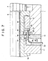
- FIG. 7 shows still another embodiment of the present invention, in which a part of the inlet pipe 28 or the outlet pipe 29 is not to be a flexible tube, but an elbow 38 is used to provide a rigid pipe bended at right angle.
- Other constitutions are the same as those described previously.
- FIG. 8 shows another embodiment of the present invention, in which the thrust plate 12 is constituted separately from the bearing 6, and the intermediate plate 10 of the present invention is replaced by the thrust plate 12.
- the inlet pipe 28 and the outlet pipe 29 are extended in an axial direction, and the guide portion 32 for loosely inserting the inlet pipe 28 and the outlet pipe 29 into the cover 11 and the flange of the viscous seal 16 is provided in parallel with the shaft center of the rotor 2.
- the guide portion 32 is formed to be considerably larger than the inlet pipe 28 and the outlet pipe 29 to facilitate mounting of the cover 11.
- a bite pipe joint 39 is provided between the end of the guide portion 32 of the viscous seal 16 and the inlet pipe 28 and the outlet pipe 29 to prevent leakage of liquid.
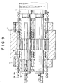
- FIG. 9 shows still another embodiment of the present invention, in which shows a gear pump of the type having no intermediate plate 10.
- Members common to those described in the respective embodiments described previously are designated by the same reference numerals, description of which is omitted.
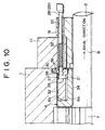
- FIG. 10 shows the main part of FIG. 9.
- the guide portion 32 parallel with the axial direction is formed extending through the cover 1 and the flange of the viscous seal 16.
- the hole of the guide portion 32 is provided concentric with the axial hole 26, and is formed to be larger than the outside diameter of the inlet pipe 28 or the outlet pipe 29.
- a portion located at the guide portion 32 of the cover 11 is formed from a flexible tube.
- the guide portion 32 is made larger in diameter, and a part of the pipe is made flexible whereby when the cover 11 is mounted, the inlet pipe 28 and the outlet pipe 29 are centered to the guide portion 32 to facilitate the insertion.
- the first O-ring 36 as seal means is provided on the peripheral edge of the guide portion 32.
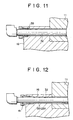
- FIG. 11 shows the details of a seal construction between the inlet pipe 28 and the outlet pipe 29, and the end of the guide portion 32 of the viscous seal 16, both of which are sealed by a bite pipe joint 39.
- an O-ring 41 is used in place of the bite pipe joint to carry out sealing.
- Ag plating is applied to the inner circumferential surface of the bearing 6.
- plating As described, even if the peripheral speed of the rotor shaft part 8 is 0.5 m/s or more, the long service life of 10 ⁇ 20 years can be achieved together with the cooling construction of the bearing 6.
- the gear pump in which a pair of gear rotors 2 are supported on a body 1 of the gear pump through a bearing 6, a cover for preventing the bearing 6 from being slipped out is secured to the body 1, and a temperature adjusting medium passage 20 is formed in the bearing 6, wherein an inlet pipe 28 and an outlet pipe 29 to the temperature adjusting medium passage 20 are connected to the axial outer end of the bearing 6, an intermediate plate 10 is interposed between the axial outer end of the bearing 6 and the cover 11, the intermediate plate 10 being provided with an insert hole 31 for the inlet pipe 28 and the outlet pipe 29, the cover 11 being provided with a guide portion 32 having the inlet pipe 28 and the outlet pipe 29 loosely fitted therein to guide them to outside. Further, at least a part of the inlet pipe 28 and the outlet pipe 29 is formed from a flexible member.
Landscapes
- Engineering & Computer Science (AREA)
- Mechanical Engineering (AREA)
- General Engineering & Computer Science (AREA)
- Rotary Pumps (AREA)
- Details And Applications Of Rotary Liquid Pumps (AREA)
Claims (19)
- Pompe à engrenages, avec:un corps (1)un palier (6)une paire de rotors à engrenages (2, 2) supportés dans le corps (1) par l'intermédiaire du palier (6)un couvercle (11) fixé au corps (1) pour empêcher le palier (6) de se dégager par glissement en sa direction axialeun passage (20) prévu dans le palier (6) pour le passage d'un agent régulant la températureune pipe d'admission (28) agencée à l'extrémité axiale extérieure du palier (6) et communicant avec le passage (20) pour l'agent de régulation de température; etune pipe d'évacuation (29) agencée à l'extrémité axiale extérieure du palier (6) et communicant avec le passage (20) pour l'agent de régulation de température, caractérisée en ce que le couvercle (11) comporte une partie de guidage dans laquelle la pipe d'admission (28) et la pipe d'évacuation (29) sont montées de façon lâche, afin de les guider extérieurement.
- Pompe à engrenages selon la revendication 1, caractérisée en ce qu'elle comporte une plaque intermédiaire (10) intercalée entre l'extrémité axiale extérieure du palier (6) et le couvercle (11), cette plaque intermédiaire (10) comportant un trou pour y introduire la pipe d'admission et la pipe d'évacuation (29).
- Pompe à engrenages selon la revendication 2, caractérisée en ce que le palier (6) est maintenu sur le corps (1) en un état non-sécurisé.
- Pompe à engrenages selon la revendication 2, caractérisée en ce qu'elle est prévue pour propulser des résines fondues.
- Pompe à engrenages selon la revendication 2, caractérisée en ce qu'une partie du matériau à propulser est introduit comme lubrifiant entre le palier (6) et le rotor denté (2).
- Pompe à engrenages selon la revendication 2, caractérisée en ce que la partie de guidage est abaissée en direction diamétrale du rotor (2) à l'extrémité du couvercle (11) située du coté de la plaque intermédiaire (10).
- Pompe à engrenages selon la revendication 2, caractérisée en ce que les deux faces de la plaque intermédiaire (10) comportent des surfaces d'étanchéité.
- Pompe à engrenages selon la revendication 2, caractérisée en ce que les deux surfaces terminales de la plaque intermédiaire (10) sont en contact avec le palier (6) et le couvercle (11) par l'intermédiaire d'un organe formant joint.
- Pompe à engrenages selon la revendication 2, caractérisée en ce que les pipes d'admission (28) et d'évacuation (29) sont montées sur le palier (6) par l'intermédiaire de moyens étanches (30).
- Pompe à engrenages selon la revendication 2, caractérisée en ce qu'une plaque de pression (12) forme une partie intégrante de la plaque intermédiaire (10) afin de stabiliser le palier (6) en direction axiale, la plaque de pression (12) étant distincte du palier (6).
- Pompe à engrenages selon la revendication 2, caractérisée en ce qu'elle comprend une pièce (16) formant un joint de viscosité pour prévenir la fuite de liquide à partir du rotor denté (2), cette pièce (16) étant disposée à une extrémité axiale extérieure du palier (6), et des moyens de fixation prévus sur la pièce (16) pour augmenter la pression sur les surfaces de montage de la plaque intermédiaire (10) et du couvercle (11).
- Pompe à engrenages selon la revendication 1, caractérisée en ce qu'au moins une partie de la pipe d'admission (28) est formée par un organe flexible, et qu'au moins une partie de la pipe d'évacuation (29) est formée par un organe flexible.
- Pompe à engrenages selon la revendication 12, caractérisée en ce que la partie de guidage (32) est parallèle à l'axe central du rotor denté (2) et que son diamètre est supérieur à celui de la pipe d'admission (28) et de la pipe d'évacuation (29).
- Pompe à engrenages selon la revendication 12, caractérisée en ce qu'elle comprend une plaque intermédiaire (10) insérée entre l'extrémité axiale extérieure du palier (6) et le couvercle (11), la plaque intermédiaire (10) comportant un trou prévu pour y faire passer la pipe d'admission (28) et la pipe d'évacuation (29).
- Pompe à engrenages selon la revendication 12, caractérisée en ce que le palier (6) est maintenu sur le corps (1) de façon non-sécurisée.
- Pompe à engrenages selon la revendication 12, caractérisée en ce qu'elle est prévue pour propulser des résines fondues.
- Pompe à engrenages selon la revendication 12, caractérisée en ce qu'une partie du matériau à propulser est introduit comme lubrifiant entre le palier (6) et le rotor denté (2).
- Pompe à engrenages selon la revendication 12, caractérisée en ce que la partie de guidage est abaissée en direction diamétrale du rotor (2) à l'extrémité du couvercle (11) située du coté de la plaque intermédiaire (10).
- Pompe à engrenages selon la revendication 14, caractérisée en ce qu'elle comprend une pièce (16) formant un joint de viscosité pour prévenir la fuite de liquide à partir du rotor denté (2), cette pièce (16) étant disposée à une extrémité extérieure du palier (6), et des moyens de fixation prévus sur la pièce (16) pour augmenter la pression sur les surfaces de montage de la plaque intermédiaire (10) et du couvercle (11).
Applications Claiming Priority (4)
| Application Number | Priority Date | Filing Date | Title |
|---|---|---|---|
| JP2000336650A JP3854058B2 (ja) | 2000-11-02 | 2000-11-02 | ギヤポンプ |
| JP2000336651 | 2000-11-02 | ||
| JP2000336650 | 2000-11-02 | ||
| JP2000336651A JP3895537B2 (ja) | 2000-11-02 | 2000-11-02 | ギヤポンプ |
Publications (3)
| Publication Number | Publication Date |
|---|---|
| EP1203885A2 EP1203885A2 (fr) | 2002-05-08 |
| EP1203885A3 EP1203885A3 (fr) | 2003-02-26 |
| EP1203885B1 true EP1203885B1 (fr) | 2004-08-04 |
Family
ID=26603388
Family Applications (1)
| Application Number | Title | Priority Date | Filing Date |
|---|---|---|---|
| EP01126024A Expired - Lifetime EP1203885B1 (fr) | 2000-11-02 | 2001-10-31 | Pompe à engrenages |
Country Status (3)
| Country | Link |
|---|---|
| US (1) | US6524088B2 (fr) |
| EP (1) | EP1203885B1 (fr) |
| DE (1) | DE60104627T2 (fr) |
Families Citing this family (13)
| Publication number | Priority date | Publication date | Assignee | Title |
|---|---|---|---|---|
| US9482225B2 (en) | 2012-06-04 | 2016-11-01 | Honeywell International Inc. | Gear pump, pumping apparatus including the same, and aircraft fuel system including gear pump |
| CN102748298B (zh) * | 2012-06-13 | 2015-05-20 | 珠海格力电器股份有限公司 | 一种旋转压缩机吸气结构 |
| WO2014059016A1 (fr) | 2012-10-10 | 2014-04-17 | Research Triangle Institute | Fluide de transfert de chaleur particulaire et système et méthode associés |
| CN104533784A (zh) * | 2014-12-22 | 2015-04-22 | 常熟市董浜镇徐市鸿磊五金机械厂 | 一种高温齿轮泵 |
| CZ305742B6 (cs) * | 2015-02-13 | 2016-02-24 | Jihostroj A.S. | Zubové čerpadlo s pohonem |
| ITUB20153710A1 (it) * | 2015-08-06 | 2017-02-06 | Jurop S P A | Compressore volumetrico a lobi per una attrezzatura e/o un impianto di aspirazione di materiale in forma liquida, solida, polverosa o fangosa |
| GB201614327D0 (en) * | 2016-08-22 | 2016-10-05 | Rolls-Royce Controls And Data Services Ltd | Gear pump bearing |
| GB201614326D0 (en) * | 2016-08-22 | 2016-10-05 | Rolls-Royce Controls And Data Services Ltd | Gear pump bearing |
| DE102016225851A1 (de) * | 2016-12-21 | 2018-06-21 | Robert Bosch Gmbh | Außenzahnradpumpe für ein Abwärmerückgewinnungssystem |
| CN107448380A (zh) * | 2017-09-26 | 2017-12-08 | 镇江沃尔夫重工部件有限公司 | 一种齿轮泵 |
| CN108150410A (zh) * | 2017-12-27 | 2018-06-12 | 郑州沃华机械有限公司 | 一种专门用于橡胶生产装置的熔体齿轮泵 |
| CN117231498A (zh) * | 2023-09-18 | 2023-12-15 | 山东鸿泰鼎新材料科技有限公司 | 用于制造莱赛尔纤维的原液增压泵及控制原液泄漏方法 |
| CN118008791A (zh) * | 2024-02-21 | 2024-05-10 | 宁波得利时泵业有限公司 | 一种适用于高粘度的转子泵 |
Family Cites Families (6)
| Publication number | Priority date | Publication date | Assignee | Title |
|---|---|---|---|---|
| DE349786C (de) * | 1919-04-23 | 1922-03-09 | Viktor Bauer | Gekuehltes Gleitlager |
| GB264105A (en) * | 1926-10-02 | 1927-01-13 | Krupp Fried Grusonwerk Ag | Improvements in or relating to bearings for the journals of shafts and rollers |
| US3976405A (en) * | 1974-10-29 | 1976-08-24 | Cominco Ltd. | Pump |
| JPH0645135B2 (ja) | 1990-10-08 | 1994-06-15 | 株式会社神戸製鋼所 | 溶融樹脂用ギアポンプ |
| EP0715078B1 (fr) * | 1996-02-09 | 2001-11-07 | Maag Pump Systems Textron AG | Pompe à engrenages |
| JP3894991B2 (ja) * | 1996-11-05 | 2007-03-22 | 株式会社神戸製鋼所 | 溶融樹脂用ギアポンプとその運転方法 |
-
2001
- 2001-10-31 DE DE60104627T patent/DE60104627T2/de not_active Expired - Lifetime
- 2001-10-31 EP EP01126024A patent/EP1203885B1/fr not_active Expired - Lifetime
- 2001-11-01 US US09/984,999 patent/US6524088B2/en not_active Expired - Lifetime
Also Published As
| Publication number | Publication date |
|---|---|
| EP1203885A2 (fr) | 2002-05-08 |
| DE60104627D1 (de) | 2004-09-09 |
| US6524088B2 (en) | 2003-02-25 |
| EP1203885A3 (fr) | 2003-02-26 |
| US20020051720A1 (en) | 2002-05-02 |
| DE60104627T2 (de) | 2005-07-28 |
Similar Documents
| Publication | Publication Date | Title |
|---|---|---|
| US6524088B2 (en) | Gear pump having a bearing with a temperature adjusting medium passage | |
| EP1788290B1 (fr) | Dispositif de joint mécanique | |
| JP5580532B2 (ja) | メカニカルシール装置 | |
| CN100434775C (zh) | 机械密封轴承保护器 | |
| AU694688B2 (en) | Bearing housing seal | |
| EP1975412A2 (fr) | Dispositif de joint d'arbre pour compresseur rotatif sans huile | |
| CN101815853A (zh) | 涡轮增压器轴承组件及其润滑 | |
| US8231130B2 (en) | Mechanical seal device | |
| US7240656B2 (en) | Electric oil pump | |
| CA2750744A1 (fr) | Joint d'etancheite d'arbre expulseur, a travail statique et dynamique et resistant a la pression | |
| UA73875C2 (en) | A loading device for a shaft furnace | |
| CN104395038B (zh) | 电动工具 | |
| US5292237A (en) | Melt pump | |
| EP1203894B1 (fr) | Dispositif de refroidissement pour un palier | |
| CA2703389C (fr) | Pompe a engrenages | |
| JP3895537B2 (ja) | ギヤポンプ | |
| US6338491B1 (en) | Rotary shaft seal | |
| JP3854058B2 (ja) | ギヤポンプ | |
| US7220111B2 (en) | Hydraulic pump | |
| JP5225675B2 (ja) | メカニカルシール装置 | |
| US12050069B2 (en) | Heat exchange apparatus for cooling oil | |
| KR102941202B1 (ko) | 단열 및 유체차단구조를 가진 고온용 고성능 로터리 조인트 | |
| KR19990007248A (ko) | 유압 펌프 | |
| US7278840B2 (en) | Compliant viscous seal for fluid transfer device | |
| KR200243800Y1 (ko) | 편심 요동축용 밀봉장치 |
Legal Events
| Date | Code | Title | Description |
|---|---|---|---|
| PUAI | Public reference made under article 153(3) epc to a published international application that has entered the european phase |
Free format text: ORIGINAL CODE: 0009012 |
|
| 17P | Request for examination filed |
Effective date: 20011031 |
|
| AK | Designated contracting states |
Kind code of ref document: A2 Designated state(s): AT BE CH CY DE DK ES FI FR GB GR IE IT LI LU MC NL PT SE TR |
|
| AX | Request for extension of the european patent |
Free format text: AL;LT;LV;MK;RO;SI |
|
| PUAL | Search report despatched |
Free format text: ORIGINAL CODE: 0009013 |
|
| AK | Designated contracting states |
Kind code of ref document: A3 Designated state(s): AT BE CH CY DE DK ES FI FR GB GR IE IT LI LU MC NL PT SE TR Designated state(s): AT BE CH CY DE DK ES FI FR GB GR IE IT LI LU MC NL PT SE TR |
|
| AX | Request for extension of the european patent |
Extension state: AL LT LV MK RO SI |
|
| 17Q | First examination report despatched |
Effective date: 20030526 |
|
| AKX | Designation fees paid |
Designated state(s): CH DE LI |
|
| GRAP | Despatch of communication of intention to grant a patent |
Free format text: ORIGINAL CODE: EPIDOSNIGR1 |
|
| GRAS | Grant fee paid |
Free format text: ORIGINAL CODE: EPIDOSNIGR3 |
|
| GRAA | (expected) grant |
Free format text: ORIGINAL CODE: 0009210 |
|
| AK | Designated contracting states |
Kind code of ref document: B1 Designated state(s): CH DE LI |
|
| REG | Reference to a national code |
Ref country code: CH Ref legal event code: EP |
|
| REG | Reference to a national code |
Ref country code: IE Ref legal event code: FG4D |
|
| REF | Corresponds to: |
Ref document number: 60104627 Country of ref document: DE Date of ref document: 20040909 Kind code of ref document: P |
|
| REG | Reference to a national code |
Ref country code: CH Ref legal event code: NV Representative=s name: E. BLUM & CO. PATENTANWAELTE |
|
| PLBE | No opposition filed within time limit |
Free format text: ORIGINAL CODE: 0009261 |
|
| STAA | Information on the status of an ep patent application or granted ep patent |
Free format text: STATUS: NO OPPOSITION FILED WITHIN TIME LIMIT |
|
| 26N | No opposition filed |
Effective date: 20050506 |
|
| REG | Reference to a national code |
Ref country code: CH Ref legal event code: PFA Owner name: KABUSHIKI KAISHA KOBE SEIKO SHO (KOBE STEEL LTD.) Free format text: KABUSHIKI KAISHA KOBE SEIKO SHO (KOBE STEEL LTD.)#3-18, WAKINOHAMA-CHO 1-CHOME, CHUO-KU#KOBE SHI, HYOGO 651-0072 (JP) -TRANSFER TO- KABUSHIKI KAISHA KOBE SEIKO SHO (KOBE STEEL LTD.)#3-18, WAKINOHAMA-CHO 1-CHOME, CHUO-KU#KOBE SHI, HYOGO 651-0072 (JP) |
|
| PGFP | Annual fee paid to national office [announced via postgrant information from national office to epo] |
Ref country code: DE Payment date: 20201020 Year of fee payment: 20 Ref country code: CH Payment date: 20201015 Year of fee payment: 20 |
|
| REG | Reference to a national code |
Ref country code: DE Ref legal event code: R071 Ref document number: 60104627 Country of ref document: DE |
|
| REG | Reference to a national code |
Ref country code: CH Ref legal event code: PL |