EP1204012B1 - Contrôle et méthode de chauffage utilisé pour le dégivrage utilisé en aviation - Google Patents
Contrôle et méthode de chauffage utilisé pour le dégivrage utilisé en aviation Download PDFInfo
- Publication number
- EP1204012B1 EP1204012B1 EP01309058A EP01309058A EP1204012B1 EP 1204012 B1 EP1204012 B1 EP 1204012B1 EP 01309058 A EP01309058 A EP 01309058A EP 01309058 A EP01309058 A EP 01309058A EP 1204012 B1 EP1204012 B1 EP 1204012B1
- Authority
- EP
- European Patent Office
- Prior art keywords
- heater
- switch
- power
- control
- probe
- Prior art date
- Legal status (The legal status is an assumption and is not a legal conclusion. Google has not performed a legal analysis and makes no representation as to the accuracy of the status listed.)
- Expired - Lifetime
Links
Images


Classifications
-
- G—PHYSICS
- G05—CONTROLLING; REGULATING
- G05D—SYSTEMS FOR CONTROLLING OR REGULATING NON-ELECTRIC VARIABLES
- G05D23/00—Control of temperature
- G05D23/19—Control of temperature characterised by the use of electric means
- G05D23/1906—Control of temperature characterised by the use of electric means using an analogue comparing device
- G05D23/1913—Control of temperature characterised by the use of electric means using an analogue comparing device delivering a series of pulses
Definitions
- the present invention relates to an active heater control that is used in connection with aerospace probes that sense environmental parameters, such as pitot or pitot-static tubes, fuselage mounted total air temperature sensors, and engine inlet air temperature sensors, which all employ heaters to keep the probes free of icing during aircraft operation.
- the heaters usually are on continuously in flight, and during selected periods of time on the ground.
- the active heater control circuit of the present invention reduces heater power during conditions of low mass air flow thereby avoiding heater or probe damage or other performance problems.
- Active heater controllers using semiconductor switches such as power MOSFETs, transistors, triacs, and SCRs are often utilized as switches to control power to resistive heating elements.
- a major impediment to the use of such active devices on aerospace probes is their incompatibility with existing aircraft systems. The problem lies with the aircraft current monitoring circuitry which expects relatively high, substantially continuous current levels typical of existing probes.
- An AHC will pulse the current in the form of regular on/off cycles in order to achieve temperature control. On/off cycling is desirable because it reduces power dissipation in the active device. It is preferable to have the active device, or switch, either fully “on” or “off” as opposed to an intermediate state, which forces the active device to dissipate power in order to control heater element current to a desired level.
- Active temperature control is achieved by controlling the "on” and “off” periods of the active device, allowing the thermal inertia of the probe to smooth out the final probe temperature. To maintain reasonable temperature control, the "off” period often becomes too long, sometimes on the order of seconds. Aircraft current monitors presently used interpret these dormant or off period, (i.e., when the current draw is Obero) as a probe heater failure. The indication of failure is unacceptable and has prevented active heat controller usage on existing aircraft without modifying the aircraft's current monitoring circuitry, a costly and impractical task for aircraft already in service.
- the present invention provides an active heater control circuit for controlling a heater for a probe on an aircraft, comprising a power control for the heater including a power source, a switch for controlling connection of the power source to the heater to provide power to the heater, a control circuit for turning on the switch, a sensor for providing a probe temperature signal to the control circuit, the control circuit turning on the switch as a function of the probe temperature signal, and an override circuit providing an override signal to the switch for providing power to the heater at selected intervals independently of the control circuit.
- the present invention also provides in combination with a probe on an aircraft across which air flows, the probe having a heater thereon powered by electrical pulse signals, an active heater control circuit connected to said heater including a power source, a switch for controlling connection of the power source to the heater, a first control having an off state and an on state for turning on the switch when the temperature indicated by the probe is less than a set point temperature, and a second control comprising a periodic signal to turn on the switch regardless of the state of the first control.
- the present invention further provides a method of controlling power to a de-icing heater on an aircraft probe, comprising providing a power source, energizing the heater with the power source through a control in response to signals indicating the probe temperature is below a desired set point temperature, and providing power to the heater at selected periods of time independently of the signals indicating the probe temperature.
- An active heater control controls a probe or sensor heater so that the time that the heater is on when there is low mass flow past the probe is short enough to avoid heater damage and other problems with thermal stresses in the probe or sensor assembly while being compatible with existing aircraft current monitoring circuitry. False signaling of unintended heater failures is avoided by providing an "off" period of the active device that is less than the time constant interval of the aircraft's current monitoring circuit.
- the active heater control circuitry can be modified to generate a series of override pulses which effectively force the active switch to turn on regardless of the probe housing temperature.
- temperature control operations will proceed as normal. The end result is the controller will always be on for a predetermined minimum time at a rate constant enough to assure the aircraft current monitor does not signal a probe heater failure, when none has occurred.
- the present invention provides pulses that will activate the heater on the aircraft probe at periods of time that will insure the aircraft's current monitoring circuitry will sense that the heater is functioning, without over heating the probe itself. For example, if a probe is off, for example, 4 seconds, the aircraft current monitoring circuitry would indicate that the probe heater was inoperative or had failed, and would provide a signal indicating failure. If the probe is on for a short period of time at periods less than the time for the current monitor to signal failure, that is, for example, every three seconds, the aircraft current monitor would recognize that the heater was functioning.
- Figure 1 is a schematic representation of a typical control circuit for a probe heater, including a heater control circuit having override pulses that control an active switch to insure powering the heater at selected minimum periods of time;
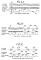
- Figure 2A is a time line set of signals showing the input power signal, a gated pulse signal, which controls the active switch, and timer override pulses during a full "on" condition, when there is high mass flow past the probe;
- Figure 2B is a time line representation of the same signals as in Figure 2A when there is moderate mass flow past the probe or sensor;
- Figure 2C is a time line representation which has the same components as Figure 2A at a condition when there is low mass flow past the probe, and the override pulses are causing heater energization at the selected minimum periods of time;
- Figure 3 is a plot showing the difference between a temperature profile of a heater controlled with the automatic heater control of the present invention, and a standard nickel based heater temperature profile with a high minimum current threshold;
- Figure 4 is a plot similar to Figure 3, using a low minimum current threshold
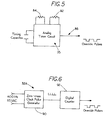
- Figure 5 is a schematic of an analog timer circuit to provide override pulses
- Figure 6 is a schematic of a digital counter timer circuit, which is synchronized to the 400 HZ AC power, that can also be used to provide override impulses.
- a probe 10 which can be a pitot pressure sensing probe, a pitot static pressure sensing probe, and exteriorly mounted total air temperature sensor, an engine inlet total air temperature sensor, an angle of attack probe or other sensor assembly, as desired is mounted on an aircraft represented at 13.
- the probe 10 is provided with a probe heater 12 that normally is a resistance type heater integrated into the probe, particularly along leading edges and other surfaces where ice accretes, so that the probe will deice in a normal manner.
- the probe heater 12 is controlled by an active heater control circuit 14.
- the 12 heater is powered by an alternating current power source 16, shown as a 400 Hz supply, and controlled by a switch circuit 18 forming part of heater control circuit 14.
- the switch circuit 18, can be for example, a triac, or other switching element that will supply power to the heater whenever gating pulses 20 are sent to it.
- the switch circuit 18 is controlled, as represented schematically, by a central control 22 that will be responsive to a set point signal from temperature set point circuit 24 that sets a desired temperature of the probe 10.
- a probe temperature signal 26 represents the temperature sensed by a suitable sensor 25 on the probe 10.
- the control 22 will stop gate control 20 from sending gate pulses to the switch thereby preventing further heating of the probe.
- the control 22 will continue to enable gate control 20 to send gating pulses to the switch circuit 18.
- an inhibit temperature signal can be provided from a settable source 28 to the control 22, and if the sensed temperature at the probe, as provided by the probe temperature signal 26, exceeds the inhibit temperature, the control 22 will also shut off all power to the probe heater 12.
- the inhibit mode is to protect the circuit or the probe itself and is an anomalous event, invoked only if needed for safety reasons.
- the inhibit signal also can be used to indicate the heater is off to the aircraft current monitor 15.
- a pulse generator 32 can override the control 22 and provide gated pulses to the switch circuit 18.
- Pulse generator 32 has an adjustable pulse duration control 34, and an adjustable pulse period control 36.
- the override pulse from the pulse generator 32 forces gate pulses as shown in Figure 2C, to be sent to switch circuit 18 for a selected duration and repetition rate so as to ensure that power is sent to the probe heater at regular intervals of time.
- the length of time between pulses or the pulse period is selected to be less than the aircraft current monitor failure mode time period. In other words the override pulse period is less than the elapsed time set for the aircraft current monitor 15 to indicate that the heater has failed.
- FIG. 2A is a graphic representation of the "full-on" mode of the active heater power control circuit 14.
- the illustrated power to heater 12 is indicated at 40, and is disclosed as a 400 Hz alternating current signal.
- the gating pulses to switch circuit 18 are shown as positive pulses 42 from a zero or base line 44.
- the switch circuit 18 controls power to the probe heater 12, in response to gate signals from control gate 20.
- the timer override pulses from the pulse generator 32 are illustrated along the line 46, and as can be seen, there is an override pulse 48 provided at selected periods indicated by the double arrow line 50.
- the time period 50 is less than the time sensed by the aircraft current monitor, which would indicate that the heaters are not functioning and have failed. In the full-on mode the override pulses do not affect operation of the heater since the heater is on continuously.
- Figure 2B illustrates the condition where there would be an active control of the probe heater 12 during moderate mass flow.
- the control 22 keeps the switch circuit 18 on for a selected period of time, after which the control 22 would block pulses to the heater because the probe temperature 26 would equal the set temperature 24 for example. The control 22 would then no longer call for power to be provided to the heater.
- the power is provided to the heater by control 22 at time periods that are longer than the period indicating to the aircraft current monitor that the heater has failed.
- the alternating current power to heater 12 again is indicated at 40, and the gated pulses to switch circuit 18 are indicated at 42.
- the timer override pulses indicated at 48 are also shown in Figure 2B.
- the temperature of the probe After a time period indicated by the vertical line 52, the temperature of the probe would be at the temperature set point and control 22 would no longer indicate that pulses should be provided to switch circuit 18. Subsequent to that time, indicated by vertical line 52, when an override pulse indicated at 48A is provided from the override pulse generator 32 to the gating circuit 20, the switch circuit 18 would be turned on and pulses indicated at 42A would be provided to switch circuit 18, which passes the AC voltage 40A to the probe heater for the length of time or duration of the override pulse 48A.
- an override pulse 48B will again energize or turn on the gate circuit 20, which will provide gated pulses 42B to be provided to switch circuit 18, and hence AC power 40B to the heater 12 for the short time of the override pulse. This will indicate to the aircraft current monitor that the probe heater is still working.
- each of the override pulses shown at 48C, 48D, 48E, and 48F would activate the gate circuit 20, sending appropriate gate pulses 42C-42F to switch circuit 18 causing the AC power as indicated by 40C-40F to be sent to the heater 12.
- the period of time between override pulses indicated by the line 50 is less than the aircraft current monitor time period that would be an indication of heater failure due to no power to the heater.
- the slope of the line 60 indicates that the temperature of the housing, which is along the vertical line, would be relatively high with very low mass flow, but the override pulses would keep the temperature of the probe lower than with a nickel-based heater shown by the plot 64.
- the override pulse mode is along the segment of the base line of mass flow indicated by the double arrow 66, where control 22 would be inactive. Along the mass flow segment 68 the control 22 enables gate pulses to be sent to switch circuit 18 as shown by 40 in Figure 2B. As the mass flow is increased to the right or the end of the double arrow 68, control 22 enables continuous gate pulses to switch circuit 18 as indicated in Figure 2A.
- Figure 5 is a block diagram representation of an analog pulse generator 32 for providing the override pulses, utilizing a resistor 82 that sets the pulse repetition rate and a resistor 84 that will set the duty cycle or the percentage of on time of the pulse.
- the output of the override pulses is indicated at 86.
- the digital override pulse generator includes a zero cross clock pulse generator 90 that outputs pulses to a digital counter 92 which provides override pulses of a selected duration and interval, based upon the count of the clock pulses.
- the effectiveness of the temperature control can be considered as a function of mass flow of air over the probe.
- the degree of temperature control achieved by the automatic heater control circuit with the override feature is dependant upon the aircraft current monitor characteristics and the chosen override design parameters, such as the override pulse period and duty cycle.
- the probe housing or probe set point temperature will determine the characteristics of operation. Even though the housing set point temperature may be exceeded during low mass flow conditions using the override pulses, the temperature is still significantly lower than that found using a nickel-based heater during the intervals as illustrated at lines 66 and 74 in Figures 3 and 4.
- Figure 3 shows operations when the intended aircraft has a current monitor having a high minimum current threshold.
- Figure 4 shows the probe operating under control across a much broader range of mass flow, while the inhibit and off regions are compressed (at very low mass flows).
- the version shown in Figure 4 is intended for aircraft that have a much lower minimum current threshold set on the aircraft current monitor.
- the automatic heater control circuit with the override pulse feature, provides a stable probe temperature near the desired housing set point temperature.
- the override pulse duty cycle that is, varying the override pulse cycle time "on” relative to time “off” but the temperature control set point can be changed as well.
- the set point temperature can be selected on an individual unit basis during manufacturing, tailored to the particular probe, such as a total air temperature sensor, to meet de-icing heater error specifications.
- the need to meet a maximum de-icing heater error is a common requirement for engine inlet temperature and total air temperature sensors.
- Additional advantages of an automatic heater control circuit that will reduce the likelihood of damage from excessive temperatures include the ability to select alternative materials for aerospace sensors including unique structural materials for housings, and robust reliable heating element alloys rather than just nickel or other positive temperature coefficient material. By insuring that the sensor does not overheat, and yet that there will be no indication from the aircraft current monitors that the heater has failed, when it has not, the design areas are opened. Enhanced anti-icing and de-icing performance of heated probes is also achieved through the ability to use increased power in the heaters of aerospace probes. The increased power is supplied in response to extreme flight conditions and within limits of aircraft power supply, and with the present invention, overheating at lower mass flows is avoided.
- Automatic heater controls or reactive heater control circuit configurations can provide an over temperature inhibit feature, as noted schematically in Figure 1, and also as shown in Figures 3 and 4, as the "inhibit mode". At very low mass flows, or in still air conditions, the housing temperature is held below some upper limit to protect either the circuit or the aircraft probe itself. Operation in the inhibit mode would be an anomalous event invoked only if needed for safety reasons.
Landscapes
- Physics & Mathematics (AREA)
- General Physics & Mathematics (AREA)
- Engineering & Computer Science (AREA)
- Automation & Control Theory (AREA)
- Control Of Resistance Heating (AREA)
- Control Of Temperature (AREA)
Claims (12)
- Circuit de commande de dispositif de chauffage actif pour commander un dispositif de chauffage d'une sonde sur un avion, comportant une commande d'énergie pour le dispositif de chauffage incluant une source d'énergie, un commutateur pour commander une connexion de la source d'énergie au dispositif de chauffage afin de délivrer de l'énergie au dispositif de chauffage, un circuit de commande pour rendre passant le commutateur, un capteur pour délivrer un signal de température de sonde au circuit de commande, le circuit de commande rendant passant le commutateur en fonction du signal de température de sonde, et un circuit de priorité délivrant un signal prioritaire au commutateur pour délivrer de l'énergie au circuit de chauffage à des intervalles sélectionnés indépendamment du circuit de commande.
- Circuit selon la revendication 1, dans lequel de l'énergie est délivrée au dispositif de chauffage sous la forme d'une série d'impulsions d'énergie transmises par une porte à travers le commutateur, lesdites impulsions d'énergie étant délivrées au dispositif de chauffage pendant un rapport cyclique du signal prioritaire.
- Circuit de commande selon l'une des revendications 1 ou 2, dans lequel le dispositif de chauffage fait partie d'une commande d'avion, le circuit de commande incluant un appareil de surveillance de courant qui indique une défaillance si de l'énergie est absente du dispositif de chauffage pendant une période de temps surveillée, l'intervalle sélectionné dudit signal prioritaire étant à une fréquence qui est sélectionnée afin d'être inférieure à la période de temps surveillée.
- Circuit de commande de dispositif de chauffage actif selon la revendication 1, dans lequel ladite énergie est délivrée audit dispositif de chauffage sous la forme d'impulsions commandées par le commutateur, et le signal prioritaire active le commutateur à des instants voulus, et pendant des durées sélectionnées pour indiquer un fonctionnement continu du dispositif de chauffage.
- Circuit de commande de dispositif de chauffage actif selon l'une quelconque des revendications 1, 2 ou 4, comportant un circuit de point de consigne délivrant un signal de point de consigne au circuit de commande, le circuit de commande rendant passant le commutateur uniquement lorsque le signal de température est inférieur au signal de point de consigne.
- Combinaison avec une sonde sur un avion à travers laquelle de l'air circule, la sonde ayant un dispositif de chauffage positionné dessus alimenté par des signaux d'impulsions électriques, un circuit de commande de dispositif de chauffage actif connecté audit dispositif de chauffage incluant une source d'énergie, un commutateur pour commander une connexion de la source d'énergie au dispositif de chauffage, une première commande ayant un état passant et un état bloqué pour rendre passant le commutateur lorsque la température indiquée par la sonde est inférieure à une température de point de consigne, et une seconde commande comportant un signal périodique pour rendre passant le commutateur sans tenir compte de l'état de la première commande.
- Combinaison selon la revendication 6, dans laquelle la source d'énergie délivre un signal de courant alternatif, et le commutateur est une porte qui transmet le signal de courant alternatif sous la forme d'une série d'impulsions transmises par la porte en réponse à au moins l'une parmi les première et seconde commandes.
- Combinaison selon la revendication 6 ou 7, et d'un circuit pour délivrer un signal d'interdiction indiquant une température au-dessus de laquelle le commutateur est mis hors service, ledit circuit destiné à délivrer un signal d'interdiction étant connecté audit commutateur pour mettre hors service ledit commutateur.
- Combinaison selon la revendication 6, dans laquelle ladite seconde commande comporte un générateur d'impulsions, ledit générateur d'impulsions délivrant une impulsion de commande au commutateur pour rendre passant le commutateur et délivrer de l'énergie au dispositif de chauffage dans des périodes de temps sélectionnées.
- Procédé de commande d'énergie à un dispositif de chauffage dégivrant sur une sonde d'avion, comportant les étapes consistant à fournir une source d'énergie, alimenter le dispositif de chauffage à l'aide de la source d'énergie par l'intermédiaire d'une commande en réponse aux signaux indiquant que la température de la sonde est inférieure à une température de point de consigne voulue, et délivrer de l'énergie au dispositif de chauffage dans des périodes de temps sélectionnées indépendamment des signaux indiquant la température de la sonde.
- Procédé selon la revendication 10, comportant l'étape consistant à fournir la commande par l'intermédiaire d'un commutateur afin de commander l'énergie de la source d'énergie au dispositif de chauffage pour alimenter le dispositif de chauffage et dans lequel l'étape consistant à délivrer de l'énergie au dispositif de chauffage indépendamment des signaux indiquant la température de la sonde comporte la commande du commutateur pour délivrer de l'énergie au dispositif de chauffage dans des périodes de temps sélectionnées et pendant des durées sélectionnées pour chaque période.
- Procédé selon l'une des revendications 10 ou 11, comportant l'étape consistant à délivrer de l'énergie au dispositif de chauffage indépendamment de l'étape d'alimentation à des intervalles qui sont inférieurs à la durée sans énergie ce qui a pour résultat une indication que le dispositif de chauffage qui est commandé est défaillant.
Applications Claiming Priority (2)
| Application Number | Priority Date | Filing Date | Title |
|---|---|---|---|
| US09/704,158 US6414282B1 (en) | 2000-11-01 | 2000-11-01 | Active heater control circuit and method used for aerospace probes |
| US704158 | 2000-11-01 |
Publications (2)
| Publication Number | Publication Date |
|---|---|
| EP1204012A1 EP1204012A1 (fr) | 2002-05-08 |
| EP1204012B1 true EP1204012B1 (fr) | 2003-08-06 |
Family
ID=24828323
Family Applications (1)
| Application Number | Title | Priority Date | Filing Date |
|---|---|---|---|
| EP01309058A Expired - Lifetime EP1204012B1 (fr) | 2000-11-01 | 2001-10-25 | Contrôle et méthode de chauffage utilisé pour le dégivrage utilisé en aviation |
Country Status (3)
| Country | Link |
|---|---|
| US (1) | US6414282B1 (fr) |
| EP (1) | EP1204012B1 (fr) |
| DE (1) | DE60100563T2 (fr) |
Families Citing this family (33)
| Publication number | Priority date | Publication date | Assignee | Title |
|---|---|---|---|---|
| GB2410481B (en) * | 2004-01-30 | 2008-06-04 | Ultra Electronics Ltd | Modular aircraft control system and method |
| FR2882141B1 (fr) * | 2005-02-14 | 2007-05-04 | Airbus France Sas | Procede et dispositif pour detecter au sol l'obstruction d'une prise de pression d'un capteur de pression statique d'un aeronef |
| FR2891241B1 (fr) * | 2005-09-23 | 2009-03-13 | Airbus France Sas | Systeme de degivrage et/ou de desembuage d'une surface d'un aeronef, procede de commande d'un tel systeme, et aeronef equipe d'un tel systeme. |
| US20100116806A1 (en) * | 2007-05-08 | 2010-05-13 | Honeywell International Inc. | Automated heating system for ports susceptible to icing |
| GB2450503A (en) * | 2007-06-26 | 2008-12-31 | Ultra Electronics Ltd | Ice protection system with plural heating elements |
| US8560203B2 (en) * | 2010-07-30 | 2013-10-15 | Pratt & Whitney Canada Corp. | Aircraft engine control during icing of temperature probe |
| US9884685B2 (en) * | 2014-05-28 | 2018-02-06 | The Boeing Company | External case heater for an angle of attack sensor |
| CN104635793B (zh) * | 2014-11-19 | 2018-04-13 | 中国航空工业集团公司沈阳飞机设计研究所 | 飞机上迎侧角传感器及空速管自动加温系统及控制方法 |
| GB201503138D0 (en) | 2015-02-25 | 2015-04-08 | Rolls Royce Controls & Data Services Ltd | Icing prevention of a pressure sensing assembly |
| US10179654B2 (en) * | 2015-10-20 | 2019-01-15 | Honeywell International Inc. | Architecture for air data probe power supply control |
| US9939459B2 (en) * | 2016-04-19 | 2018-04-10 | The Boeing Company | System and method for performing a test on a pitot probe heating element |
| US11060992B2 (en) | 2017-03-24 | 2021-07-13 | Rosemount Aerospace Inc. | Probe heater remaining useful life determination |
| US10564203B2 (en) * | 2017-03-24 | 2020-02-18 | Rosemount Aerospace Inc. | Probe heater remaining useful life determination |
| US10895592B2 (en) | 2017-03-24 | 2021-01-19 | Rosemount Aerospace Inc. | Probe heater remaining useful life determination |
| US10914777B2 (en) | 2017-03-24 | 2021-02-09 | Rosemount Aerospace Inc. | Probe heater remaining useful life determination |
| US10716171B2 (en) * | 2018-03-23 | 2020-07-14 | Rosemount Aerospace Inc. | Power efficient heater control of air data sensor |
| US11524790B2 (en) | 2018-08-21 | 2022-12-13 | Honeywell International Inc. | Enhanced pitot tube power management system and method |
| US11016117B2 (en) | 2018-08-31 | 2021-05-25 | Honeywell International Inc. | Air data probe replacement determination system |
| US10962580B2 (en) | 2018-12-14 | 2021-03-30 | Rosemount Aerospace Inc. | Electric arc detection for probe heater PHM and prediction of remaining useful life |
| US11061080B2 (en) | 2018-12-14 | 2021-07-13 | Rosemount Aerospace Inc. | Real time operational leakage current measurement for probe heater PHM and prediction of remaining useful life |
| US10908132B2 (en) | 2019-01-07 | 2021-02-02 | Goodrich Corporation | Real-time performance and health monitoring of ice detector systems and estimation of remaining useful life |
| US11604209B2 (en) * | 2019-05-17 | 2023-03-14 | Rosemount Aerospace Inc. | Pitot heater health monitoring system |
| CN110203404B (zh) * | 2019-05-21 | 2022-05-03 | 中国商用飞机有限责任公司 | 飞机大气数据系统的加温控制装置 |
| US11639954B2 (en) | 2019-05-29 | 2023-05-02 | Rosemount Aerospace Inc. | Differential leakage current measurement for heater health monitoring |
| US11472562B2 (en) * | 2019-06-14 | 2022-10-18 | Rosemount Aerospace Inc. | Health monitoring of an electrical heater of an air data probe |
| US11459112B2 (en) * | 2019-07-19 | 2022-10-04 | Rosemount Aerospace Inc. | Active aircraft probe heat monitor and method of use |
| US11930563B2 (en) | 2019-09-16 | 2024-03-12 | Rosemount Aerospace Inc. | Monitoring and extending heater life through power supply polarity switching |
| US11422153B2 (en) | 2020-01-24 | 2022-08-23 | Honeywell International Inc. | Air data probe replacement determination system |
| US11293995B2 (en) | 2020-03-23 | 2022-04-05 | Rosemount Aerospace Inc. | Differential leakage current measurement for heater health monitoring |
| US11630140B2 (en) | 2020-04-22 | 2023-04-18 | Rosemount Aerospace Inc. | Prognostic health monitoring for heater |
| CN112004271B (zh) * | 2020-07-24 | 2022-11-18 | 西安爱生技术集团公司 | 一种小型无人机空速管的智能加热器 |
| CA3143784C (fr) * | 2021-02-18 | 2025-09-09 | The Boeing Company | Appareil, systemes et methodes pour gerer des evenements pneumatiques en mode commun |
| CN116972588B (zh) * | 2023-07-25 | 2026-02-27 | 无锡和晶智能科技有限公司 | 一种可温控的半导体冰箱控制器 |
Family Cites Families (9)
| Publication number | Priority date | Publication date | Assignee | Title |
|---|---|---|---|---|
| US2221547A (en) | 1938-03-12 | 1940-11-12 | Square D Co | Heat protected pitot-static tube |
| GB1181216A (en) | 1966-07-26 | 1970-02-11 | Rosemount Eng Co Ltd | Improvements in or relating to Aerodynamic Components Mounted Externally on an Aircraft |
| US4121088A (en) | 1976-10-18 | 1978-10-17 | Rosemount Inc. | Electrically heated air data sensing device |
| US4156350A (en) * | 1977-12-27 | 1979-05-29 | General Electric Company | Refrigeration apparatus demand defrost control system and method |
| US4458137A (en) | 1981-04-09 | 1984-07-03 | Rosemount Inc. | Electric heater arrangement for fluid flow stream sensors |
| US5134380A (en) * | 1986-02-10 | 1992-07-28 | Otakar Jonas | Icing detector and method |
| FR2703786B1 (fr) * | 1993-04-07 | 1995-06-23 | Intertechnique Sa | Procede et dispositif a ultrasons de detection et d'identification de contaminant tel que le givre a la surface d'une structure. |
| US5464965A (en) * | 1993-04-20 | 1995-11-07 | Honeywell Inc. | Apparatus for controlling temperature of an element having a temperature variable resistance |
| US5611952A (en) * | 1994-06-30 | 1997-03-18 | Jones; Thaddeus M. | Temperature sensor probe and sensor detection circuit |
-
2000
- 2000-11-01 US US09/704,158 patent/US6414282B1/en not_active Expired - Lifetime
-
2001
- 2001-10-25 EP EP01309058A patent/EP1204012B1/fr not_active Expired - Lifetime
- 2001-10-25 DE DE60100563T patent/DE60100563T2/de not_active Expired - Fee Related
Also Published As
| Publication number | Publication date |
|---|---|
| DE60100563D1 (de) | 2003-09-11 |
| US6414282B1 (en) | 2002-07-02 |
| DE60100563T2 (de) | 2004-06-17 |
| EP1204012A1 (fr) | 2002-05-08 |
Similar Documents
| Publication | Publication Date | Title |
|---|---|---|
| EP1204012B1 (fr) | Contrôle et méthode de chauffage utilisé pour le dégivrage utilisé en aviation | |
| US6753513B2 (en) | Propeller de-icing system | |
| US5464965A (en) | Apparatus for controlling temperature of an element having a temperature variable resistance | |
| EP0076306B1 (fr) | Systeme passif de commande de temperature pour un radiateur de detecteur de courant d'ecoulement fluide | |
| US4514619A (en) | Indirect current monitoring via voltage and impedance monitoring | |
| US6211494B1 (en) | Drainmast with integral electronic temperature control | |
| CN101267982A (zh) | 飞行器表面的除霜和/或除雾系统、控制该系统的方法以及装备该系统的飞行器 | |
| US4745629A (en) | Duty cycle timer | |
| CA1196709A (fr) | Methode de depistage de la raison d'etre du mauvais fonctionnement d'un dispositif thermostatique | |
| US5323062A (en) | System for triac trigger control in combination with a sensing element | |
| WO1991019170A1 (fr) | Detecteur de debit et systeme de commande | |
| EP0333233B1 (fr) | Méthode de détection du mauvais fonctionnement des circuits de chauffage dans un système de chauffage pour colles thermofusibles à plusieurs composants | |
| JPH05746Y2 (fr) | ||
| JPS6120761A (ja) | サ−マルヘツドの温度制御回路 | |
| JPH0115240B2 (fr) | ||
| KR950009883Y1 (ko) | 전기장판의 자동온도 조절장치 | |
| JP2543024B2 (ja) | ポンプの保護装置 | |
| GB2156098A (en) | Control of electric heating apparatus | |
| JPH0729597Y2 (ja) | セラミックヒータの安全装置 | |
| US20200278133A1 (en) | Continuous-flow heater with a safety circuit | |
| JPS61128026A (ja) | 燃焼制御装置用安全回路 | |
| JP2908902B2 (ja) | 電気採暖器 | |
| JPH02183176A (ja) | ヒーターの断線検出装置 | |
| WO2002026559A1 (fr) | Drain d'evacuation a circuit electronique integre de regulation de la temperature | |
| JPH0613925B2 (ja) | ガス事故防止装置 |
Legal Events
| Date | Code | Title | Description |
|---|---|---|---|
| PUAI | Public reference made under article 153(3) epc to a published international application that has entered the european phase |
Free format text: ORIGINAL CODE: 0009012 |
|
| AK | Designated contracting states |
Kind code of ref document: A1 Designated state(s): AT BE CH CY DE DK ES FI FR GB GR IE IT LI LU MC NL PT SE TR |
|
| AX | Request for extension of the european patent |
Free format text: AL;LT;LV;MK;RO;SI |
|
| 17P | Request for examination filed |
Effective date: 20020726 |
|
| GRAH | Despatch of communication of intention to grant a patent |
Free format text: ORIGINAL CODE: EPIDOS IGRA |
|
| AKX | Designation fees paid |
Designated state(s): DE FR GB |
|
| GRAH | Despatch of communication of intention to grant a patent |
Free format text: ORIGINAL CODE: EPIDOS IGRA |
|
| GRAA | (expected) grant |
Free format text: ORIGINAL CODE: 0009210 |
|
| AK | Designated contracting states |
Designated state(s): DE FR GB |
|
| REG | Reference to a national code |
Ref country code: GB Ref legal event code: FG4D |
|
| REG | Reference to a national code |
Ref country code: IE Ref legal event code: FG4D |
|
| REF | Corresponds to: |
Ref document number: 60100563 Country of ref document: DE Date of ref document: 20030911 Kind code of ref document: P |
|
| ET | Fr: translation filed | ||
| PLBE | No opposition filed within time limit |
Free format text: ORIGINAL CODE: 0009261 |
|
| STAA | Information on the status of an ep patent application or granted ep patent |
Free format text: STATUS: NO OPPOSITION FILED WITHIN TIME LIMIT |
|
| 26N | No opposition filed |
Effective date: 20040507 |
|
| REG | Reference to a national code |
Ref country code: IE Ref legal event code: MM4A |
|
| PGFP | Annual fee paid to national office [announced via postgrant information from national office to epo] |
Ref country code: FR Payment date: 20051017 Year of fee payment: 5 |
|
| PGFP | Annual fee paid to national office [announced via postgrant information from national office to epo] |
Ref country code: DE Payment date: 20051130 Year of fee payment: 5 |
|
| PG25 | Lapsed in a contracting state [announced via postgrant information from national office to epo] |
Ref country code: DE Free format text: LAPSE BECAUSE OF NON-PAYMENT OF DUE FEES Effective date: 20070501 |
|
| GBPC | Gb: european patent ceased through non-payment of renewal fee |
Effective date: 20061025 |
|
| REG | Reference to a national code |
Ref country code: FR Ref legal event code: ST Effective date: 20070629 |
|
| PG25 | Lapsed in a contracting state [announced via postgrant information from national office to epo] |
Ref country code: GB Free format text: LAPSE BECAUSE OF NON-PAYMENT OF DUE FEES Effective date: 20061025 |
|
| PG25 | Lapsed in a contracting state [announced via postgrant information from national office to epo] |
Ref country code: FR Free format text: LAPSE BECAUSE OF NON-PAYMENT OF DUE FEES Effective date: 20061031 |
|
| PGFP | Annual fee paid to national office [announced via postgrant information from national office to epo] |
Ref country code: GB Payment date: 20051019 Year of fee payment: 5 |