EP1204084A1 - Dispositif d'information pour une vehicule automobile et méthode correspondante - Google Patents
Dispositif d'information pour une vehicule automobile et méthode correspondante Download PDFInfo
- Publication number
- EP1204084A1 EP1204084A1 EP01125804A EP01125804A EP1204084A1 EP 1204084 A1 EP1204084 A1 EP 1204084A1 EP 01125804 A EP01125804 A EP 01125804A EP 01125804 A EP01125804 A EP 01125804A EP 1204084 A1 EP1204084 A1 EP 1204084A1
- Authority
- EP
- European Patent Office
- Prior art keywords
- section
- information
- service information
- vehicle
- light emitting
- Prior art date
- Legal status (The legal status is an assumption and is not a legal conclusion. Google has not performed a legal analysis and makes no representation as to the accuracy of the status listed.)
- Granted
Links
- 238000000034 method Methods 0.000 title claims description 13
- 238000004891 communication Methods 0.000 claims abstract description 20
- 238000010586 diagram Methods 0.000 description 10
- 230000008901 benefit Effects 0.000 description 6
- 238000012986 modification Methods 0.000 description 4
- 230000004048 modification Effects 0.000 description 4
- 238000003491 array Methods 0.000 description 2
- 230000005540 biological transmission Effects 0.000 description 2
- 238000012790 confirmation Methods 0.000 description 2
- 230000000694 effects Effects 0.000 description 2
- 238000005401 electroluminescence Methods 0.000 description 2
- 230000006870 function Effects 0.000 description 2
- 230000003287 optical effect Effects 0.000 description 1
Images




Classifications
-
- G—PHYSICS
- G01—MEASURING; TESTING
- G01C—MEASURING DISTANCES, LEVELS OR BEARINGS; SURVEYING; NAVIGATION; GYROSCOPIC INSTRUMENTS; PHOTOGRAMMETRY OR VIDEOGRAMMETRY
- G01C21/00—Navigation; Navigational instruments not provided for in groups G01C1/00 - G01C19/00
- G01C21/26—Navigation; Navigational instruments not provided for in groups G01C1/00 - G01C19/00 specially adapted for navigation in a road network
- G01C21/265—Navigation; Navigational instruments not provided for in groups G01C1/00 - G01C19/00 specially adapted for navigation in a road network constructional aspects of navigation devices, e.g. housings, mountings, displays
-
- G—PHYSICS
- G01—MEASURING; TESTING
- G01C—MEASURING DISTANCES, LEVELS OR BEARINGS; SURVEYING; NAVIGATION; GYROSCOPIC INSTRUMENTS; PHOTOGRAMMETRY OR VIDEOGRAMMETRY
- G01C21/00—Navigation; Navigational instruments not provided for in groups G01C1/00 - G01C19/00
- G01C21/26—Navigation; Navigational instruments not provided for in groups G01C1/00 - G01C19/00 specially adapted for navigation in a road network
- G01C21/34—Route searching; Route guidance
- G01C21/36—Input/output arrangements for on-board computers
- G01C21/3688—Systems comprising multiple parts or multiple output devices (not client-server), e.g. detachable faceplates, key fobs or multiple output screens
-
- G—PHYSICS
- G08—SIGNALLING
- G08G—TRAFFIC CONTROL SYSTEMS
- G08G1/00—Traffic control systems for road vehicles
- G08G1/09—Arrangements for giving variable traffic instructions
- G08G1/0962—Arrangements for giving variable traffic instructions having an indicator mounted inside the vehicle, e.g. giving voice messages
Definitions
- the present invention relates to an information providing system and a method, more particularly, to an information providing system and a method for providing information, which is received from an outside information center, to a driver of a vehicle.
- a navigation apparatus as an information providing system, of a vehicle, which enables a driver to request local information such as weather or traffic conditions at a destination area to an information center to receive desired information which is displayed over a display screen in a manner as disclosed in Japanese Patent Application Laid-Open Publication NO. 2000-121375.
- the display screen since the display screen immediately displays the contents of received information when it is received from the information center, the display of received information forcibly calls for the driver's attention in spite of driving the vehicle in any circumferential situation, with a difficulty caused in paying a careful attention to the circumferential situation.
- an information providing system of a vehicle providing information from an outside section to the vehicle is provided with: a communication section making a request to the outside section for transmitting a pre-selected service information and receiving the requested service information from the outside section; a memory section storing the requested service information received from the outside section; an information providing section providing the received information stored in the memory section; a light emitting section located in a frontal visible area of the vehicle; and a control section controlling the information providing section and the light emitting section.
- the control section turns on the light emitting section for a first time interval when the requested service information is received and after that, allows the information providing section to provide the stored service information.
- a method of providing information from an outside section to a vehicle requests a pre-selected service information to the outside section; receives the requested service information from the outside section; stores the received service information; provides the stored information in the vehicle; emits a light at a frontal visible area of the vehicle; and controls a timing at which the light is emitted and a timing at which the stored information is provided.
- the light is emitted for a first time interval when the requested service information is received and after that, the stored service information is provided.
- the information providing system 10 is located in a vehicle V and arranged to receive service information from an information center 12 which may be connected to a database DB that stores service information, such as a weather information, a positional information, a destination area information, a traffic information, an e-mail information, and a news information, etc. Further, the information center 12 may be also connected to web sites WB. Though not shown in FIG. 1, the information center 12 includes a computer which controls the receipt of an information request issued by the information providing system 10 and the transmission of requested information to the information providing system 10. The information center 12 also includes a radio communication unit, though not shown, to transmit requested information to the information providing system 10.
- the information providing system 10 includes a radio communication unit 20, which is composed of a computer (not shown) including a CPU for requesting various service information to the information center 12 according to a user's information request and receiving the requested service information transmitted from the information center 12, and a controller (not shown) for controlling the transmission of the information request and the receipt of the service information transmitted from the information center 12.
- the information providing system 10 also includes an information request section 22 which is constructed with an operation unit 24 enabling a driver to input an information request to request the desired service information to the information center 12, and a register unit 26 which stores therein a menu for objects to be accessed so as to access the desired service information of the database and the web sites from the information center 12.
- Each selected object to be accessed is displayed in a monitor section 28 when operating the operation unit 24, thereby enabling the driver to selectively manipulate the operation unit 24 for accessing the object, i.e., the desired service information while looking at the monitor section 28.
- the information providing system 10 includes a memory section 30, a display light control section 32 and a light emitting section 34.
- Service information received at the radio communication unit 20 is stored in the memory section 30.
- the display light control section 32 functions to turn on the light emitting section 34 and, after a given time interval, described later in detail, to allow service information to be retrieved from the memory section 30 to be displayed over the monitor section 28.
- the light emitting section 34 is composed of laterally spaced, substantially vertically extending elongated arrays of light emitting diodes (LEDs) 34a, 34b mounted on respective inner walls of left and right front pillars 38, 40 at both sides of a vehicle front window 42 in a driver's frontal visible range A.
- the monitor section 28 is mounted to a central area of an instrument panel 44 and, in a case where a navigation system is installed in the vehicle, may be also utilized as a display monitor of the same.
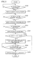
- FIG. 3 is a flow diagram of the basic sequence of operational steps to be performed in the information providing system 10 shown in FIG. 1 to carry out a method of the present invention.
- a main switch (not shown) is turned on to supply electric power to the information providing system 10, which is turned on.
- step S100 the radio communication unit 20 checks whether the operation unit 24 is operated for inputting the information request or remains un-operated. Upon the driver's operation of the operation unit 24 to request service information, in step S101, the particular objects, which correspond to the database or web sites to be accessed and are registered as a particular menu in the register unit 26, are displayed over the monitor section 28.
- step S102 the radio communication unit 20 checks whether the particular service information is selected and when it is selected, the operation goes to step S103, thereby commencing the communication between the information center 12 and the radio communication unit 20 to make a request to the information center 12 for transmitting the selected service information and allow the selected service information to be transmitted to the radio communication unit 20.
- service information involves the weather information, the positional information, the destination area information, the traffic information, the e-mail information, and the news information, etc.
- the service information may further involve a desired facility such as, for example, stations, restaurants, commercial buildings, theaters, shops, parking lots, etc., and their related information such as locations, current vacancy status, parking lot capacity and availability of parking or booking.
- the display of the objects, to be accessed, displayed over the monitor section 28 is terminated. Though not specifically shown in the drawings, further, when the objects, to be accessed, are displayed over the monitor section 28 for more than a given time period, then the display of the objects is also terminated.
- step S104 the radio communication unit 20 checks whether the selected service information is received or not yet received. If the desired information is found not to be received, then, the step S104 is repeated for each certain time interval.
- step S105 the radio communication unit 20 sends the received service information to the memory section 30, which in turns stores the received service information and delivers an output signal, representing that the received service information has been stored, to the display light control section 32.
- step S106 the display light control section 32 turns on the light emitting section 34 for a first predetermined time interval of, for example, one second.
- step S107 the display light control section 32 checks whether a second predetermined time interval has passed after the light emitting section 34 has turned on in the previous step.
- the second predetermined time interval is preferably determined to be, for example, about two seconds such that the second predetermined time interval is expired after the light emitting section 34 has been turned off.
- the step S107 is repeatedly operated until the second predetermined time interval has elapsed.
- step S108 the display light control section 32 retrieves the selected service information, stored in the memory section 30, and allow the retrieved service information to be displayed over the monitor section 28.
- An important advantage of the present embodiment concerns the light emitting section 34 which is firstly turned on upon receipt of the demanded service information, and the monitor section 28 which is operated to display the received service information subsequent to the turning-on operation of the light emitting section 34.
- the driver's attention is conducted with the lightening of the pair of arrays of the LEDs 34a, 34b located at the left and right pillars 38, 40 toward the vehicular frontal visible range to enable confirmation of a circumferential situation in a front direction of the vehicle, thereby permitting the driver to direct his eyes over the monitor section 28 to read out the selected, desired service information in a safety fashion.
- Another important advantage of the present embodiment concerns the display light control section 32 which allows the selected service information to be displayed over the monitor section 28 at a suitable timing after the second predetermined time interval has elapsed without causing any overlooking during the driver's confirmation of the frontal circumferential situation of the vehicle, thereby facilitating the driver's recognition of the received information.
- the information providing system has been shown and described with reference to cases where, after the elapse of the second predetermined time interval from the turning-on state of the light emitting section 34, the received information is displayed over the monitor section 28, the information providing system may be further provided with an information provision delay command section 70 (shown in FIG.
- the light emitting section 34 is turned on again after a third predetermined time interval of, for example, about three to five seconds, starting from the initial turning-on of the light emitting section 34, which is longer than the second predetermined time interval and subsequently after the second predetermined time interval has elapsed from the expiration of the third predetermined time interval, the received service information is displayed over the monitor section 28 in a repeated manner each time the information provision delay command section 70 is operated.
- FIG. 4 shows an information providing system of a second embodiment of the present invention, with a detailed description of the previously described component parts with reference to FIG. 1 being omitted for the sake of simplicity.
- the second embodiment differs from the first embodiment in that an information providing system 10' newly incorporates a vehicle load discriminating section 50.
- a display light control section 32' is connected to the vehicle load discriminating section 50, which in turn is connected to a vehicle speed sensor 52, which detects the traveling speed of the vehicle to produce a vehicle speed signal, and a braking-operation detecting unit 54, which detects a braked situation of a parking brake (not shown).
- the vehicle load discriminating section 50 discriminates a vehicle's halt condition when the vehicle speed remains at zero value and the parking brake remains in its operative condition.
- the vehicle load discriminating section 50 is responsive to a signal representative of the vehicle's halt condition for allowing the received service information to be immediately displayed over the monitor section 28 without turning on the light emitting section 34.
- the display light control section 32' is operative first to allow the light emitting section 34 to be turned on as in the first embodiment and subsequently to allow the received service information to be displayed over the monitor section 28.
- FIG. 5 is a flow diagram of the basic sequence of operational steps to be performed by the information providing system 10' shown in FIG. 4 to carrying out a method of the present invention.
- steps S200 to S205 perform the same operations as steps S100 to S105 of the first embodiment shown in FIG. 3.
- the display light control section 32' Upon receiving the signal representing that the received service information has been stored in the memory section 30, in step S206, the display light control section 32' responds to the signal from the vehicle load discriminating section 50 to check whether a current vehicle's load remains at a high level.
- step S209 If the discriminated result of the vehicle load discriminating section 50 remains in the vehicle's halt condition, i.e., when the vehicle load discriminating section 50 discriminates that the vehicle load is low, the operation goes to step S209, thereby allowing the received service information to be displayed over the monitor section 28.
- Such an operation corresponds to a case wherein both the first and second predetermined time intervals are rendered to have a zero value.
- step S207 When, in contrast, the discriminated result of the vehicle load discriminating section 50 does not remain in the vehicle's halt condition, i.e., when the vehicle load remains in a heavy level, the operation goes to step S207, thereby allowing the light emitting section 34 to be turned on only for the first predetermined time interval. Further, in step S208, it is checked whether the second predetermined time interval has elapsed from the turning on timing of the light emitting section 34 and, if so, the operation goes to step S209.
- the stream in the operational steps S207 to 209 is the same as those S106 to 108 of the first embodiment discussed above.
- the information providing system 10' has the same advantages as those obtained in the first embodiment.
- Another important advantage of the second embodiment concerns the provision of the vehicle load discriminating section 50 which causes the display light control section 32' to allow the light emitting section 34 to be turned on to immediately display the received service information over the monitor section 28, without turning on the light emitting section 34, when the vehicle remains in the light load condition for thereby enabling the driver to timely confirm the received service information according to the driving status of the vehicle.
- the information providing system has been shown and described with reference to cases where, after the elapse of the second predetermined time interval from the turning-on state of the light emitting section 34, the received information is displayed over the monitor section 28, the information providing system may be further provided with an information provision delay command section 70 (shown in FIG.
- a delay command signal responsive to the driver's operation such that upon receipt of the delay command signal delivered from the information provision delay command section 70, the light emitting section 34 is turned on again after a third predetermined time interval of, for example, about three to five seconds, starting from the initial turning-on of the light emitting section 34, which is longer than the second predetermined time interval and subsequently after the second predetermined time interval has elapsed from the expiration of the third predetermined time interval, the received service information is displayed over the monitor section 28 in a repeated manner each time the information provision delay command section 70 is operated.
- a third predetermined time interval of, for example, about three to five seconds
- FIG. 6 shows an information providing system of a third embodiment of the present invention, with a detailed description of the previously described component parts with reference to FIG. 1 being omitted for the sake of simplicity.
- the third embodiment differs from the first embodiment in that an information providing system 10" newly incorporates an information provision start-up command section 60 which is arranged to be operated by the driver.
- a display light control section 32" is connected to the information provision start-up command section 60.
- the display light control section 32" responds to the signal, representing that the received service information has been stored in the memory section 30, delivered from the memory section 30, thereby turning on the light emitting section 34 for the first predetermined time interval in the same manner as previously described above.
- the information provision start-up command section 60 if the driver operates the information provision start-up command section 60, the information provision start-up command section 60 generates an information provision start-up command signal.
- the display light control section 32" retrieves the stored information from the memory section 30 to display the same over the monitor section 28.
- FIG. 7 is a flow diagram of the basic sequence of operational steps to be performed by the information providing system 10" shown in FIG. 6 to carry out a method of the present invention.
- steps S300 to S306 perform the same operations as the steps S100 to S106 of the first embodiment shown in FIG. 3.
- step S307 the display light control section 32" checks whether it receives the information provision start-up command, i.e., the information provision start-up signal from the information provision start-up command section 60.
- the display light control section 32" repeats the step S307 until it receives the provision start-up signal.
- step S308 Upon receipt of the provision start-up signal, the operation goes to step S308 such that the display light control section 32" retrieves the stored information from the memory section 30 to display the same over the monitor section 28.
- the light emitting section 34 is first turned on when the requested service information is received in the memory section 30 and subsequently after the driver operates the information provision start-up command section 60, the received information is displayed over the monitor section 28.
- attention is called for the driver with the lighting on state of the light emitting section 34 toward the frontal area of the vehicle to permit the driver to confirm the circumferential situation of the vehicle, thereby confirming the received service information at an arbitrary timing with his willing in an adequate time interval.
- the display light control section functions to turn on the light emitting section 34 for the predetermined time interval
- the display light control section may be modified so as to periodically flash the light emitting section 34 on and off at a predetermined frequency.
- the light emitting section 34 has been shown and described as including the two rows of LEDs 34a, 34b which are mounted to the inner wall of the front left and right pillars 38, 40 of the front window 42, the present invention is not limited thereto and the light emitting section 34 may be constructed of a row of LEDs mounted to an inner wall of a roof panel along a frontal, upper edge thereof or a row of LEDs mounted to an edge portion of the instrument panel along an area in the vicinity of a lower edge of the front window such that the light emitting section 34 surely calls for the driver's attention toward the frontal area through the front window 42.
- the light emitting section 34 may not be limited to a particular structure of the row of the LEDs arranged in a surface configuration, but may be composed of other light emitting elements, such as EL device (electroluminescence device) or fluorescence light tube, formed in the surface configuration or in the array configuration, or a light conductive and light diffusive type optical member such as a light guide.
- EL device electroluminescence device
- fluorescence light tube formed in the surface configuration or in the array configuration
- a light conductive and light diffusive type optical member such as a light guide.
- the light emitting section 34 may be composed of a light emitting element such as a transparent EL device (electroluminescence device) which does not disturb the visibility during the non-turning on state.
- a transparent EL device electrospray device
- the light emitting section 34 may be arranged to be turned on for a given time interval or to be flashed on and off even when the communication is established between the information center 12 and the radio communication unit 20 by selecting the particular service information with the information request section 22 to request the same.
- the radio communication unit 20 may be preset such that the desired service information is periodically requested. With such presetting operation, it is possible for the driver to regularly obtain the desired information without operating the information request section 22 each time the driver needs the desired information.
- the display light control sections 32, 32', 32" have been shown and described as being responsive to the signal, which represents that the memory section 30 has stored the received service information, for controlling the light emitting section 34, the information providing system may be modified such that the display light control section receives a signal, which represents that the requested service information has been received, directly from the radio communication unit 20 to perform the control of the display light control section or the like.
- the information providing system of the present invention has been shown and described with reference to the example wherein the received service information is visually displayed over the monitor section 28, the present invention is not limited thereto and the received service information is provided with voice information. Even in such a modification, it is possible for the light emitting section 34 to be turned on to call the driver's attention toward the frontal area of the vehicle to enable the driver first to confirm the circumferential situation and subsequently to listen to voice information with a sense of security.
Landscapes
- Engineering & Computer Science (AREA)
- Radar, Positioning & Navigation (AREA)
- Remote Sensing (AREA)
- Physics & Mathematics (AREA)
- General Physics & Mathematics (AREA)
- Automation & Control Theory (AREA)
- Traffic Control Systems (AREA)
- Instrument Panels (AREA)
Applications Claiming Priority (2)
| Application Number | Priority Date | Filing Date | Title |
|---|---|---|---|
| JP2000334994 | 2000-11-01 | ||
| JP2000334994A JP4293723B2 (ja) | 2000-11-01 | 2000-11-01 | 車両用情報提示装置 |
Publications (2)
| Publication Number | Publication Date |
|---|---|
| EP1204084A1 true EP1204084A1 (fr) | 2002-05-08 |
| EP1204084B1 EP1204084B1 (fr) | 2004-01-07 |
Family
ID=18810812
Family Applications (1)
| Application Number | Title | Priority Date | Filing Date |
|---|---|---|---|
| EP01125804A Expired - Lifetime EP1204084B1 (fr) | 2000-11-01 | 2001-10-29 | Dispositif d'information pour une vehicule automobile et méthode correspondante |
Country Status (4)
| Country | Link |
|---|---|
| US (1) | US6694250B2 (fr) |
| EP (1) | EP1204084B1 (fr) |
| JP (1) | JP4293723B2 (fr) |
| DE (1) | DE60101718T2 (fr) |
Cited By (3)
| Publication number | Priority date | Publication date | Assignee | Title |
|---|---|---|---|---|
| CN101876751A (zh) * | 2009-04-02 | 2010-11-03 | 通用汽车环球科技运作公司 | 在全挡风玻璃平视显示器上的车辆间通讯装置 |
| WO2013189737A1 (fr) * | 2012-06-20 | 2013-12-27 | Here Global B.V. | Procédé et appareil pour l'utilisation d'un faisceau de lumière de dispositif comme rétroaction à des fins de guidage |
| DE102012210750A1 (de) | 2012-06-25 | 2014-04-24 | Bayerische Motoren Werke Aktiengesellschaft | Lichtleiste in Fahrzeug zur Anzeige von Informationen von Fahrerassistenzfunktionen |
Families Citing this family (6)
| Publication number | Priority date | Publication date | Assignee | Title |
|---|---|---|---|---|
| JP4609185B2 (ja) * | 2005-05-25 | 2011-01-12 | 日産自動車株式会社 | 注意誘導装置及び注意誘導方法 |
| JP4923835B2 (ja) * | 2006-08-10 | 2012-04-25 | 株式会社デンソー | 報知装置及び報知システム |
| EP2080674B1 (fr) * | 2008-01-15 | 2011-03-23 | SMR Patents S.à.r.l. | Système d'urgence pour véhicule |
| DE102010056411A1 (de) * | 2010-12-23 | 2012-06-28 | Volkswagen Ag | Anzeigevorrichtung für ein Kraftfahrzeug |
| CN102219004A (zh) * | 2011-04-26 | 2011-10-19 | 宏景电子(芜湖)有限公司 | 一种汽车智能管理系统及其管理方法 |
| JP5821859B2 (ja) | 2013-01-18 | 2015-11-24 | 株式会社デンソー | 表示システム |
Citations (5)
| Publication number | Priority date | Publication date | Assignee | Title |
|---|---|---|---|---|
| EP0647753A1 (fr) * | 1993-10-08 | 1995-04-12 | Trw Inc. | Récepteur destiné à être utilisé dans un système d'entrée sans clé et à recevoir des émissions radiodiffusées publiques |
| US5568390A (en) * | 1993-08-10 | 1996-10-22 | Toyota Jidosha Kabushiki Kaisha | Navigation system to be mounted on vehicles |
| EP0771686A2 (fr) * | 1995-11-06 | 1997-05-07 | Toyota Jidosha Kabushiki Kaisha | Dispositif d'affichage d'informations pour véhicules |
| US5938721A (en) * | 1996-10-24 | 1999-08-17 | Trimble Navigation Limited | Position based personal digital assistant |
| US6028537A (en) * | 1996-06-14 | 2000-02-22 | Prince Corporation | Vehicle communication and remote control system |
Family Cites Families (9)
| Publication number | Priority date | Publication date | Assignee | Title |
|---|---|---|---|---|
| US6002326A (en) * | 1994-09-19 | 1999-12-14 | Valerie Turner | Automotive vehicle anti-theft and anti-vandalism and anti-carjacking system |
| DE69535394T2 (de) * | 1994-12-28 | 2007-10-31 | Omron Corp. | Verkehrsinformationssystem |
| GB9520478D0 (en) * | 1995-10-06 | 1995-12-06 | West Glamorgan County Council | Monitoring system |
| US6150928A (en) * | 1996-04-24 | 2000-11-21 | Murray; Steve | Multi passenger frequency controlled alarm system |
| US6202024B1 (en) * | 1998-03-23 | 2001-03-13 | Kabushikikaisha Equos Research | Communicatory navigation system |
| JP2000121375A (ja) | 1998-10-15 | 2000-04-28 | Alpine Electronics Inc | ナビゲーション装置 |
| TW472221B (en) * | 1999-01-29 | 2002-01-11 | Matsushita Electric Industrial Co Ltd | Emergency reporting system and terminal apparatus therein |
| US6166627A (en) * | 1999-07-20 | 2000-12-26 | Reeley; Ronald B. | Mobile detection and alert system |
| JP4599649B2 (ja) * | 2000-03-09 | 2010-12-15 | 株式会社エクォス・リサーチ | データ通信ネットワークにおける課金処理装置 |
-
2000
- 2000-11-01 JP JP2000334994A patent/JP4293723B2/ja not_active Expired - Fee Related
-
2001
- 2001-10-24 US US09/983,375 patent/US6694250B2/en not_active Expired - Fee Related
- 2001-10-29 EP EP01125804A patent/EP1204084B1/fr not_active Expired - Lifetime
- 2001-10-29 DE DE60101718T patent/DE60101718T2/de not_active Expired - Lifetime
Patent Citations (6)
| Publication number | Priority date | Publication date | Assignee | Title |
|---|---|---|---|---|
| US5568390A (en) * | 1993-08-10 | 1996-10-22 | Toyota Jidosha Kabushiki Kaisha | Navigation system to be mounted on vehicles |
| US5568390B1 (en) * | 1993-08-10 | 1998-03-31 | Toyota Motor Co Ltd | Navigation system to be mounted on vehicles |
| EP0647753A1 (fr) * | 1993-10-08 | 1995-04-12 | Trw Inc. | Récepteur destiné à être utilisé dans un système d'entrée sans clé et à recevoir des émissions radiodiffusées publiques |
| EP0771686A2 (fr) * | 1995-11-06 | 1997-05-07 | Toyota Jidosha Kabushiki Kaisha | Dispositif d'affichage d'informations pour véhicules |
| US6028537A (en) * | 1996-06-14 | 2000-02-22 | Prince Corporation | Vehicle communication and remote control system |
| US5938721A (en) * | 1996-10-24 | 1999-08-17 | Trimble Navigation Limited | Position based personal digital assistant |
Cited By (4)
| Publication number | Priority date | Publication date | Assignee | Title |
|---|---|---|---|---|
| CN101876751A (zh) * | 2009-04-02 | 2010-11-03 | 通用汽车环球科技运作公司 | 在全挡风玻璃平视显示器上的车辆间通讯装置 |
| CN101876751B (zh) * | 2009-04-02 | 2012-10-03 | 通用汽车环球科技运作公司 | 在全挡风玻璃平视显示器上的车辆间通讯装置 |
| WO2013189737A1 (fr) * | 2012-06-20 | 2013-12-27 | Here Global B.V. | Procédé et appareil pour l'utilisation d'un faisceau de lumière de dispositif comme rétroaction à des fins de guidage |
| DE102012210750A1 (de) | 2012-06-25 | 2014-04-24 | Bayerische Motoren Werke Aktiengesellschaft | Lichtleiste in Fahrzeug zur Anzeige von Informationen von Fahrerassistenzfunktionen |
Also Published As
| Publication number | Publication date |
|---|---|
| JP2002137655A (ja) | 2002-05-14 |
| US6694250B2 (en) | 2004-02-17 |
| DE60101718T2 (de) | 2004-06-17 |
| JP4293723B2 (ja) | 2009-07-08 |
| EP1204084B1 (fr) | 2004-01-07 |
| US20020052686A1 (en) | 2002-05-02 |
| DE60101718D1 (de) | 2004-02-12 |
Similar Documents
| Publication | Publication Date | Title |
|---|---|---|
| JP7004077B2 (ja) | 車両の走行制御方法及び走行制御装置 | |
| KR102331763B1 (ko) | 내비게이션 장치와 연동하여 자율 주차와 자율 주행을 제어하는 장치 및 방법 | |
| JP6128824B2 (ja) | 車両相互間通信による駐車空間情報提供方法およびシステム | |
| US6335693B1 (en) | Information exchange system | |
| US6957128B1 (en) | Vehicle information processing method, apparatus therefor and vehicle therewith | |
| US11782434B2 (en) | Driving plan generating apparatus, remote driving server, and method for generating driving plan | |
| US20130166109A1 (en) | Driver Red Light Duration Notification System | |
| US6694250B2 (en) | Information providing system and method | |
| KR20120018005A (ko) | 주차 관리 서비스 방법 및 장치, 주차 관리 서비스를 위한 클라이언트 단말 및 서버 | |
| JP2004192366A (ja) | 配車システム | |
| JP2002109689A (ja) | バス乗車支援システム | |
| JP7316469B1 (ja) | 自動車にビジュアルコンテンツを表示する方法およびシステム、ならびに自動車を提供する方法 | |
| US20050273232A1 (en) | Automobile communication courtesy display | |
| JP2002286471A (ja) | ルート案内システム | |
| KR102162309B1 (ko) | 주차장 내 주차 맞춤 안내 시스템 | |
| KR100762316B1 (ko) | 버스 승차 정보 시스템 및 방법 | |
| JP2018088193A (ja) | 対象識別システム、駐車場装置及び自動車 | |
| KR19990036454A (ko) | 정기 정규 고정 노선을 운행하는 차량의 운행을 제어하는시스템 및 방법 | |
| KR101534696B1 (ko) | 차량 제어 장치 및 그 방법 | |
| KR20030037703A (ko) | 광고 표시 관리 시스템 | |
| KR20000060943A (ko) | 주차장 안내장치 및 안내방법 | |
| KR200357367Y1 (ko) | 주차유도 관리시스템 | |
| JP2005156400A (ja) | 狭域通信システム | |
| JPH08169657A (ja) | エレベータのホール案内表示装置 | |
| Mezarcıöz et al. | Smart Transportation Applications and Vehicle Data Processing System for Smart City Buses |
Legal Events
| Date | Code | Title | Description |
|---|---|---|---|
| PUAI | Public reference made under article 153(3) epc to a published international application that has entered the european phase |
Free format text: ORIGINAL CODE: 0009012 |
|
| 17P | Request for examination filed |
Effective date: 20011029 |
|
| AK | Designated contracting states |
Kind code of ref document: A1 Designated state(s): AT BE CH CY DE DK ES FI FR GB GR IE IT LI LU MC NL PT SE TR |
|
| AX | Request for extension of the european patent |
Free format text: AL;LT;LV;MK;RO;SI |
|
| AKX | Designation fees paid |
Designated state(s): DE FR GB |
|
| 17Q | First examination report despatched |
Effective date: 20030110 |
|
| GRAH | Despatch of communication of intention to grant a patent |
Free format text: ORIGINAL CODE: EPIDOS IGRA |
|
| GRAS | Grant fee paid |
Free format text: ORIGINAL CODE: EPIDOSNIGR3 |
|
| GRAA | (expected) grant |
Free format text: ORIGINAL CODE: 0009210 |
|
| AK | Designated contracting states |
Kind code of ref document: B1 Designated state(s): DE FR GB |
|
| REG | Reference to a national code |
Ref country code: GB Ref legal event code: FG4D |
|
| REG | Reference to a national code |
Ref country code: IE Ref legal event code: FG4D |
|
| REF | Corresponds to: |
Ref document number: 60101718 Country of ref document: DE Date of ref document: 20040212 Kind code of ref document: P |
|
| ET | Fr: translation filed | ||
| PLBE | No opposition filed within time limit |
Free format text: ORIGINAL CODE: 0009261 |
|
| STAA | Information on the status of an ep patent application or granted ep patent |
Free format text: STATUS: NO OPPOSITION FILED WITHIN TIME LIMIT |
|
| 26N | No opposition filed |
Effective date: 20041008 |
|
| PGFP | Annual fee paid to national office [announced via postgrant information from national office to epo] |
Ref country code: DE Payment date: 20131023 Year of fee payment: 13 Ref country code: GB Payment date: 20131023 Year of fee payment: 13 Ref country code: FR Payment date: 20131009 Year of fee payment: 13 |
|
| REG | Reference to a national code |
Ref country code: DE Ref legal event code: R119 Ref document number: 60101718 Country of ref document: DE |
|
| GBPC | Gb: european patent ceased through non-payment of renewal fee |
Effective date: 20141029 |
|
| PG25 | Lapsed in a contracting state [announced via postgrant information from national office to epo] |
Ref country code: GB Free format text: LAPSE BECAUSE OF NON-PAYMENT OF DUE FEES Effective date: 20141029 Ref country code: DE Free format text: LAPSE BECAUSE OF NON-PAYMENT OF DUE FEES Effective date: 20150501 |
|
| REG | Reference to a national code |
Ref country code: FR Ref legal event code: ST Effective date: 20150630 |
|
| PG25 | Lapsed in a contracting state [announced via postgrant information from national office to epo] |
Ref country code: FR Free format text: LAPSE BECAUSE OF NON-PAYMENT OF DUE FEES Effective date: 20141031 |