EP1204112A2 - Ein Wiedergabegerät und Verfahren zur Wiedergabe von auf einer optischen Platte aufgezeichneten digitalen Informationen - Google Patents
Ein Wiedergabegerät und Verfahren zur Wiedergabe von auf einer optischen Platte aufgezeichneten digitalen Informationen Download PDFInfo
- Publication number
- EP1204112A2 EP1204112A2 EP01125383A EP01125383A EP1204112A2 EP 1204112 A2 EP1204112 A2 EP 1204112A2 EP 01125383 A EP01125383 A EP 01125383A EP 01125383 A EP01125383 A EP 01125383A EP 1204112 A2 EP1204112 A2 EP 1204112A2
- Authority
- EP
- European Patent Office
- Prior art keywords
- digital information
- retry
- electric signals
- optical pickup
- buffer memory
- Prior art date
- Legal status (The legal status is an assumption and is not a legal conclusion. Google has not performed a legal analysis and makes no representation as to the accuracy of the status listed.)
- Withdrawn
Links
Images


Classifications
-
- G—PHYSICS
- G11—INFORMATION STORAGE
- G11B—INFORMATION STORAGE BASED ON RELATIVE MOVEMENT BETWEEN RECORD CARRIER AND TRANSDUCER
- G11B20/00—Signal processing not specific to the method of recording or reproducing; Circuits therefor
- G11B20/10—Digital recording or reproducing
- G11B20/18—Error detection or correction; Testing, e.g. of drop-outs
-
- G—PHYSICS
- G11—INFORMATION STORAGE
- G11B—INFORMATION STORAGE BASED ON RELATIVE MOVEMENT BETWEEN RECORD CARRIER AND TRANSDUCER
- G11B19/00—Driving, starting, stopping record carriers not specifically of filamentary or web form, or of supports therefor; Control thereof; Control of operating function ; Driving both disc and head
- G11B19/02—Control of operating function, e.g. switching from recording to reproducing
- G11B19/04—Arrangements for preventing, inhibiting, or warning against double recording on the same blank or against other recording or reproducing malfunctions
-
- G—PHYSICS
- G11—INFORMATION STORAGE
- G11B—INFORMATION STORAGE BASED ON RELATIVE MOVEMENT BETWEEN RECORD CARRIER AND TRANSDUCER
- G11B27/00—Editing; Indexing; Addressing; Timing or synchronising; Monitoring; Measuring tape travel
- G11B27/10—Indexing; Addressing; Timing or synchronising; Measuring tape travel
- G11B27/34—Indicating arrangements
-
- G—PHYSICS
- G11—INFORMATION STORAGE
- G11B—INFORMATION STORAGE BASED ON RELATIVE MOVEMENT BETWEEN RECORD CARRIER AND TRANSDUCER
- G11B27/00—Editing; Indexing; Addressing; Timing or synchronising; Monitoring; Measuring tape travel
- G11B27/36—Monitoring, i.e. supervising the progress of recording or reproducing
-
- G—PHYSICS
- G11—INFORMATION STORAGE
- G11B—INFORMATION STORAGE BASED ON RELATIVE MOVEMENT BETWEEN RECORD CARRIER AND TRANSDUCER
- G11B20/00—Signal processing not specific to the method of recording or reproducing; Circuits therefor
- G11B20/10—Digital recording or reproducing
- G11B20/10527—Audio or video recording; Data buffering arrangements
- G11B2020/1062—Data buffering arrangements, e.g. recording or playback buffers
-
- G—PHYSICS
- G11—INFORMATION STORAGE
- G11B—INFORMATION STORAGE BASED ON RELATIVE MOVEMENT BETWEEN RECORD CARRIER AND TRANSDUCER
- G11B20/00—Signal processing not specific to the method of recording or reproducing; Circuits therefor
- G11B20/10—Digital recording or reproducing
- G11B20/18—Error detection or correction; Testing, e.g. of drop-outs
- G11B20/1816—Testing
- G11B2020/183—Testing wherein at least one additional attempt is made to read or write the data when a first attempt is unsuccessful
-
- G—PHYSICS
- G11—INFORMATION STORAGE
- G11B—INFORMATION STORAGE BASED ON RELATIVE MOVEMENT BETWEEN RECORD CARRIER AND TRANSDUCER
- G11B2220/00—Record carriers by type
- G11B2220/20—Disc-shaped record carriers
- G11B2220/25—Disc-shaped record carriers characterised in that the disc is based on a specific recording technology
- G11B2220/2537—Optical discs
- G11B2220/2562—DVDs [digital versatile discs]; Digital video discs; MMCDs; HDCDs
Definitions
- the present invention relates to a reproduction apparatus for and a method of reproducing digital information such as video and audio signals recorded on optical discs.
- the reproduction apparatus includes a DVD-Video player and other disc players.
- the reproduction method is performed through a retry routine to continue reproducing the digital information such as video and audio signals recorded on optical discs when the digital information cannot be read out of the optical disc operated by the DVD-Video player.
- the reproduction apparatus of this kind is designed to reproduce the digital information such as video and audio signals recorded on the optical disc by reading the digital information out of the optical disc. If the optical disc happens to have external damages such as scars, scratches, and fingerprints, the reproduction apparatus cannot normally be operated to reproduce the digital information in the addresses respectively having the external damages. For this reason, the reproduction apparatus is designed to repeat the retry routine by predetermined one more times before skipping the address or addresses to continue reproducing the digital information.
- the reproduction apparatus 180 is shown in FIG. 16 as comprising an optical pickup 112, a signal amplifying means 113, a signal processing means 114, a buffer memory 115, a signal decoding means 116, a pickup driving means 117, and a retry controlling means 118.
- the optical pickup 112 is designed to read out digital information recorded in an optical disc 111.
- the signal amplifying means 113 is operative to amplify the digital information read out by the optical pickup 112.
- the signal processing means 114 is designed to process the electric signals in one or more times of retry routines by the predetermined one or more times to correct the errors outputted as the electric signals from the signal amplifying means 113.
- the words “one or more times” will be described hereinafter as “times” for simplicity but is of course needless to say that the words include only one time.
- the word "retry routine” appearing hereinabove is intended to mean a reading operation to repeatedly read the digital information on the optical disc 111 when the optical pickup 112 fails to carry out error correction or read the digital information recorded on an optical disc 111.
- the buffer memory 115 functions temporarily as a storing memory of the signal outputted from the signal processing means 114, and the signal decoding means 116 is operative to decode the signal outputted from the buffer memory 115 to video and audio signals.
- the pickup driving means 117 is designed to drive the optical pickup 112 to move on the optical disc 111. The errors are associated with respective addresses to be targeted by the optical pickup 112 when the optical pickup 112 is moved by the pickup driving means 117.
- the retry controlling means 118 is operative to control a retry routine according to the signal outputted from the signal processing means 114.
- FIG. 17 shows a flowchart of the retry routine controlled by the retry controlling means 118 forming of part of the reproduction apparatus 180.
- the retry controlling means 118 firstly initializes the retry counter indicative of the retry times in step S204.
- the pickup driving means 117 is then instructed by the retry controlling means 118 to have the optical pickup 112 move to the target address on the optical disc 111 to reproduce the digital information in step S205.
- the retry controlling means 118 is operated to confirm whether or not the pickup driving means 117 is finished with the optical pickup 112 moved to the target address in step S206.
- the signal outputted from the optical pickup 112 is inputted to the signal amplifying means 113 where the signal is amplified.
- the pickup driving means 117 is again instructed by the retry controlling means 118 to have the optical pickup 112 move to the target address on the optical disc 111 to reproduce the digital information in step S205.
- the signal amplified by the signal amplifying means 113 is fed to the signal processing means 114 for performing the error correction process.
- the signal processing means 114 is then instructed by the retry controlling means 118 to correct errors contained in the digital information on the optical disc 111 in step S207.
- the retry controlling means 118 is then operated to confirm whether or not the error correction process is successfully performed by the signal processing means 114 in step S208.
- the signal processed by the signal processing means 114 is fed to the buffer memory 115 by the signal processing means 114.
- the retry counter is incremented by the retry controlling means 118 in step S211.
- the retry controlling means 118 is then operated to judge whether or not the retry times exceed the upper limit times through the indication of the retry counter in step S212. If the retry times do not exceed the upper limit times, the retry controlling means 118 has the optical pickup 112 continue retrying to read the digital information at the same target address until the optical pickup 112 obtains the recorded digital information on the optical disc 111 after returning to step S205.
- the retry controlling means 118 is operated to initialize the retry counter in step S213. The retry controlling means 118 is then operated to confirm whether or not the signal outputted from the signal processing means 114 is completed to be stored in the buffer memory 115 by the signal processing means 114 in step S209. When the signal outputted from the signal processing means 114 succeeds to be stored in the buffer memory 115 by the signal processing means 114 in step S209, the retry controlling means 118 is operated to replace the current target address with a new target address to obtain the next digital information on the optical disc 111 in step S210.
- the signal outputted from the signal amplifying means 113 fails to be stored in the buffer memory 115 by the signal processing means 114 in step S209, the signal outputted from the signal amplifying means 113 is again fed to the buffer memory 115 and stored in the buffer memory 115 by the signal processing means 114 until the electric signal is completely stored in the buffer memory 115.
- the retry controlling means 118 is then operated to judge whether or not the optical pickup 112 finishes reading the digital information at the final target address of the optical disc 111 in step S214. If the optical pickup 112 finishes reading the digital information at the final target address of the optical disc 111 in step S214, the retry controlling means 118 is operated to stop the retry routine. If, on the other hand, the optical pickup 112 has not finished reading the digital information at the final target address of the optical disc 111 in step S214, the process returns to the step S201.
- the video and audio information recorded on the optical disc 111 is processed with errors corrected and stored in the buffer memory 115 before being decoded by the signal decoding means 116.
- a reproduction apparatus for reproducing digital information recorded on an optical disc, comprising: an optical pickup for reading the digital information recorded on the optical disc to have the digital information converted into electric signals, the digital information containing errors appearing when the digital information is read by the optical pickup; signal amplifying means for amplifying the electric signals converted from the digital information read by the optical pickup; signal processing means for processing the electric signals in one or more times of retry routines to correct the errors outputted as the electric signals from the signal amplifying means; a buffer memory for storing the electric signals outputted from the signal processing means; signal decoding means for decoding the electric signals stored in the buffer memory and outputted from the buffer memory; pickup driving means for driving the optical pickup to move on the optical disc, the errors being associated with respective addresses to be targeted by the optical pickup when the optical pickup is moved by the pickup driving means; information residue detecting means for detecting an amount of residue digital information remaining in the buffer memory; and retry controlling means for controlling the one or more times of retry routines based on the
- a reproduction apparatus for reproducing digital information recorded on an optical disc, comprising: an optical pickup for reading the digital information recorded on the optical disc to have the digital information converted into electric signals, the digital information containing errors appearing when the digital information is read by the optical pickup; signal amplifying means for amplifying the electric signals converted from the digital information read by the optical pickup; signal processing means for processing the electric signals in one or more times of retry routines to correct the errors outputted as the electric signals from the signal amplifying means; a buffer memory for storing the electric signals outputted from the signal processing means; signal decoding means for decoding the electric signals stored in the buffer memory and outputted from the buffer memory; pickup driving means for driving the optical pickup to move on the optical disc, the errors being associated with respective addresses to be targeted by the optical pickup when the optical pickup is moved by the pickup driving means; the electric signals are decoded by the signal decoding means for a time interval; first time calculating means for calculating the time interval taken by the signal decoding means to discharge the electric signals de
- a reproduction apparatus for reproducing digital information recorded on an optical disc, comprising: an optical pickup for reading the digital information recorded on the optical disc to have the digital information converted into electric signals, the digital information containing errors appearing when the digital information is read by the optical pickup; signal amplifying means for amplifying the electric signals converted from the digital information read by the optical pickup; signal processing means for processing the electric signals in one or more times of retry routines to correct the errors outputted as the electric signals from the signal amplifying means; a buffer memory for storing the electric signals outputted from the signal processing means; signal decoding means for decoding the electric signals stored in the buffer memory and outputted from the buffer memory; pickup driving means for driving the optical pickup to move on the optical disc, the errors being associated with respective addresses to be targeted by the optical pickup when the optical pickup is moved by the pickup driving means; external damage detecting means for detecting external damages on the surface of the optical disc; and retry controlling means for controlling the one or more times of retry routines based on the
- a reproduction apparatus for reproducing digital information recorded on an optical disc comprising: an optical pickup is movable in the radial direction of the optical disc to assume radial positions to read the digital information converted into electric signals, the digital information containing errors appearing when the digital information is read by the optical pickup; signal amplifying means for amplifying the electric signals converted from the digital information read by the optical pickup; signal processing means for processing the electric signals in one or more times of retry routines to correct the errors outputted as the electric signals from the signal amplifying means; a buffer memory for storing the electric signals outputted from the signal processing means; signal decoding means for decoding the electric signals stored in the buffer memory and outputted from the buffer memory; pickup driving means for driving the optical pickup to move on the optical disc, the errors being associated with respective addresses to be targeted by the optical pickup when the optical pickup is moved by the pickup driving means; radial position detecting means for detecting the radial positions of the optical pickup; and retry controlling means for controlling the one or
- FIG. 1 of the drawings there is shown a block diagram of the first preferred embodiment of the reproduction apparatus 110 according to the invention which comprises an optical pickup 112 and signal amplifying means 113.
- the optical pickup 112 is adapted to read the digital information recorded on the optical disc 111 to have the digital information converted into electric signals.
- the digital information contains errors appearing when the digital information is read by the optical pickup 112.
- the signal amplifying means 113 is operative to amplify the electric signals converted from the digital information read by the optical pickup 112.
- the reproduction apparatus 110 further comprises signal processing means 114 and a buffer memory 115.
- the signal processing means 114 is designed to process the electric signals in one or more times of retry routines to correct the errors outputted as the electric signals from the signal amplifying means 113.
- the buffer memory 115 is operative to store the electric signals outputted from the signal processing means 114.
- times the words “one or more times” will be described hereinafter as “times” for simplicity but is of course needless to say that the words include only one time.
- the word "retry routine” appearing hereinabove is intended to mean a reading operation to repeatedly read the digital information on the optical disc 111 when the optical pickup 112 fails to carry out error correction or read the digital information recorded on an optical disc 111.
- the buffer memory 115 has a plurality of sections including first and second sections respectively having a newest address and an oldest address.
- the first section assumes a position spaced apart from the second section and in which the buffer memory 115 comprises a write pointer serving to indicate the newest address of the electric signal stored in the buffer memory 115, and a read pointer functioning to indicate the oldest address of the electric signal stored in the buffer memory 115.
- the reproduction apparatus 110 further comprises signal decoding means 116 and pickup driving means 117.
- the signal decoding means 116 is adapted to decode the electric signals stored in the buffer memory 115 and outputted from the buffer memory 115.
- the pickup driving means 117 is operative to drive the optical pickup 112 to move on the optical disc 111. The errors are associated with respective addresses to be targeted by the optical pickup 112 when the optical pickup 112 is moved by the pickup driving means 117.
- the reproduction apparatus 110 further comprises information residue detecting means 119 and retry controlling means 118.
- the information residue detecting means 119 serves to detect an amount of residue digital information remaining in the buffer memory 115.
- the retry controlling means 118 is designed to control the times of retry routines based on the amount of residue digital information detected by the information residue detecting means 119 when the digital information fails to be read out of the optical disc 111.
- the retry controlling means 118 has a retry counter indicative of the retry times and an upper limit times by which the retry routine is repeated.
- the digital information on the optical disc 111 is successfully processed by the signal processing means 114, the digital information is consecutively stored and accumulated in the buffer memory 115 because the decoding rate of the digital information decoded by the signal decoding means 116 is smaller than the reading rate of the digital information read by the optical pickup 112.
- the retry routine performed by the retry controlling means 118 is, however, required for reading the digital information recorded on the optical disc 111 when the optical pickup 112 fails to read the digital information recorded on the optical disc 111 or the signal processing means 114 fails to carry out error correction.
- the above retry routines are repeatedly performed by the retry controlling means 118 until the optical pickup 112 can read the digital information recorded on the optical disc 111 or the signal processing means 114 can carry out error correction.
- the digital information for reproducing video and audio signals is neither fed to nor stored in the buffer memory 115 though the video and audio signals in the buffer memory 115 are consecutively outputted to the signal decoding means 116.
- the buffer memory 115 is eventually reduced to its empty level before the times of retry routines become equal to the upper limit times, the buffer memory 115 has no electric signals for decoding.
- the empty level of the buffer memory 115 results in having the digital information being brought into a frozen state in which the video and audio signals remain immediately before being under the frozen state and thus are respectively displayed and outputted at a standstill without any change.
- FIG. 2 shows a flowchart of the retry routine controlled by the retry controlling means 118 forming of part of the reproduction apparatus 110.
- the retry controlling means 118 is initially operated to compare a predetermined criterion value with a detected value obtained by the information residue detecting means 119 in step S201. In this operation, the amount of the digital information stored in the buffer memory 115 is calculated by the information residue detecting means 119 based on the difference between the write pointer value and the read pointer value in the buffer memory 115. When the difference between the write pointer value and the read pointer value in the buffer memory 115 is lager than the predetermined criterion value, the retry controlling means 118 is operated to have the retry upper limit times set to a first number in step S202.
- the retry controlling means 118 When the difference between the write pointer value and the read pointer value in the buffer memory 115, on the other hand, is smaller than the predetermined criterion value, the retry controlling means 118 is in turn operated to have the retry upper limit times set to a second number, which is smaller than the first number, in step S203.
- the retry controlling means 118 then initializes the retry counter indicative of the retry times in step S204.
- the pickup driving means 117 is then instructed by the retry controlling means 118 to have the optical pickup 112 move to the target address on the optical disc 111 to reproduce the digital information in step S205.
- the retry controlling means 118 is operated to confirm whether or not the pickup driving means 117 is finished with the optical pickup 112 moved to the target address in step S206.
- the signal outputted from the optical pickup 112 is inputted to the signal amplifying means 113 where the signal is amplified.
- the pickup driving means 117 is again instructed by the retry controlling means 118 to have the optical pickup 112 move to the target address on the optical disc 111 to reproduce the digital information in step S205.
- the signal amplified by the signal amplifying means 113 is fed to the signal processing means 114 for performing the error correction process.
- the signal processing means 114 is then instructed by the retry controlling means 118 to correct errors contained in the digital information on the optical disc 111 in step S207.
- the retry controlling means 118 is then operated to confirm whether or not the error correction process is successfully performed by the signal processing means 114 in step S208.
- the signal processed by the signal processing means 114 is fed to the buffer memory 115 by the signal processing means 114.
- the retry counter is incremented by the retry controlling means 118 in step S211.
- the retry controlling means 118 is then operated to judge whether or not the retry times exceed the upper limit times through the indication of the retry counter in step S212. If the retry times do not exceed the upper limit times, the retry controlling means 118 has the optical pickup 112 continue retrying to read the digital information at the same target address until the optical pickup 112 obtains the recorded digital information on the optical disc 111 after returning to step S205.
- the retry controlling means 118 is operated to initialize the retry counter in step S213.
- the upper limit times to be changed based on the amount of residue digital information remaining in the buffer memory 115 leads to the fact that the video and audio signals can continuously be decoded without being under the frozen state.
- the retry controlling means 118 is then operated to confirm whether or not the signal outputted from the signal processing means 114 is completed to be stored in the buffer memory 115 by the signal processing means 114 in step S209.
- the retry controlling means 118 is operated to replace the current target address with a new target address to obtain the next digital information on the optical disc 111 in step S210.
- the signal outputted from the signal amplifying means 113 fails to be stored in the buffer memory 115 by the signal processing means 114 in step S209, the signal outputted from the signal amplifying means 113 is again fed to the buffer memory 115 and stored in the buffer memory 115 by the signal processing means 114 until the electric signal is completely stored in the buffer memory 115.
- the retry controlling means 118 is then operated to judge whether or not the optical pickup 112 finishes reading the digital information at the final target address of the optical disc 111 in step S214. If the optical pickup 112 finishes reading the digital information at the final target address of the optical disc 111 in step S214, the retry controlling means 118 is operated to stop the retry routine. If, on the other hand, the optical pickup 112 has not finished reading the digital information at the final target address of the optical disc 111 in step S214, the process returns to the step S201.
- the error correction for the video and audio information recorded on the optical disc 111 is performed with the upper limit times to be changed based on the amount of residue digital information remaining in the buffer memory 115 after the video and audio information is stored in the buffer memory 115 by the first embodiment of the reproduction apparatus 110 according to the present invention. This makes it possible to continuously decode video and audio signals without being under the frozen state.
- the first embodiment of the reproduction apparatus according to the present invention previously mentioned may be replaced by the second embodiment of the reproduction apparatus according to the present invention which will be described hereinafter.
- FIG. 3 of the drawings there is shown a block diagram of the second preferred embodiment of the reproduction apparatus 130 according to the invention which comprises an optical pickup 112 and signal amplifying means 113.
- the optical pickup 112 is adapted to read the digital information recorded on the optical disc 111 to have the digital information converted into electric signals.
- the digital information contains errors appearing when the digital information is read by the optical pickup 112.
- the signal amplifying means 113 is operative to amplify the electric signals converted from the digital information read by the optical pickup 112.
- the reproduction apparatus 130 further comprises signal processing means 114 and a buffer memory 115.
- the signal processing means 114 is designed to process the electric signals in times of retry routines to correct the errors outputted as the electric signals from the signal amplifying means 113.
- the buffer memory 115 is operative to store the electric signals outputted from the signal processing means 114.
- the buffer memory 115 has a write pointer and a read pointer.
- the buffer memory 115 has a plurality of sections including first and second sections respectively having a newest address and an oldest address.
- the first section assumes a position spaced apart from the second section and in which the buffer memory 115 comprises a write pointer serving to indicate the newest address of the electric signal stored in the buffer memory 115, and a read pointer functioning to indicate the oldest address of the electric signal stored in the buffer memory 115.
- the reproduction apparatus 130 further comprises signal decoding means 116 and pickup driving means 117.
- the signal decoding means 116 is adapted to decode the electric signals stored in the buffer memory 115 and outputted from the buffer memory 115.
- the pickup driving means 117 is operative to drive the optical pickup 112 to move on the optical disc 111. The errors are associated with respective addresses to be targeted by the optical pickup 112 when the optical pickup 112 is moved by the pickup driving means 117.
- the reproduction apparatus 130 has electric signals decoded by the signal decoding means 116 for a time interval.
- the reproduction apparatus 130 further comprises first time calculating means 131 and retry controlling means 118.
- the first time calculating means 131 is adapted to calculate the time interval taken by the signal decoding means 116 to discharge the electric signals decoded.
- the retry controlling means 118 is operative to control the times of retry routines based on the time interval calculated by the first time calculating means 131 when the digital information fails to be read out of the optical disc 111.
- the retry controlling means 118 has a retry counter indicative of the retry times and a retry times upper limit by which the retry routine is repeated.
- the word "retry times upper limit” is intended to mean an upper limit on how many times the retry operation is performed by the retry controlling means 118.
- the reproduction apparatus 130 further comprises a buffer memory 115, second time calculating means 132, and the retry controlling means 118.
- the buffer memory 115 has at least two buffer memory sections consisting of an initial buffer memory section having the electric signals firstly stored at an initial time and a final buffer memory section having the electric signals finally stored at a final time.
- the second time calculating means 132 is adapted to calculate the difference between the initial time and the final time for the electric signals to be stored in the initial and final buffer memory sections.
- the retry controlling means 118 is adapted to control the times of retry routines based on the difference between the initial time and the final time calculated by the second time calculating means 132.
- the reproduction apparatus 130 has the digital information having a plurality of groups of picture unit recorded on the optical disc 111 after being compressed under a specific format each of the groups of picture unit being constituted by a plurality of pictures having a first picture, a last picture, and a plurality of intermediate pictures sequentially ordered between the first picture and the last picture.
- the reproduction apparatus 130 has the electric signals decoded by the signal decoding means 116 and respectively indicative of the groups of picture unit.
- the reproduction apparatus 130 further comprises pickup driving means 117 is adapted to have the optical pickup 112 skip the address for each of the groups of picture unit when the digital information fails to be read out of the optical disc 111.
- FIG. 4 shows an information pack encoded for example by the MPEG standard, i.e., a video compression method planed by Moving Picture Experts Group, in the second preferred embodiment of the reproduction apparatus 130 according to the present invention.
- the information pack 141 is shown in FIG. 4 as being composed of a pack header 142 and a packet 143.
- the pack header 142 consists of a pack start code 144 having an entry address recorded therein, a system clock reference 145 having a criterion time information of reproducing video and audio signals recoded therein, a program multiplex rate 146 having a maximum transfer rate recoded therein, and a stuffing length 147 having a length of a padding packet, not shown, recoded therein to maintain the length of the packet 143 constant.
- the above system clock reference 145 is hereinafter simply referred to as "SCR 145".
- the packet 143 contains video and audio data.
- FIG. 5 shows a flowchart of the retry routine controlled by the retry controlling means 118 forming of part of the reproduction apparatus 130.
- the retry controlling means 118 is initially operated to compare a predetermined criterion value with a detected value obtained by the first time calculating means 131 in step S301.
- the reproducing time is calculated from converted values of the amount of the storing digital information in the buffer memory 115. If the digital information recorded on the optical disc 111 is encoded by the fixed rate compression, the reproducing time of the digital information can be obtained by the calculation of multiplying the reproducing time by constant. If, on the other hand, the digital information recorded on the optical disc 111 is encoded by the variable rate compression, the reproducing time of the digital information cannot be obtained by the above calculation.
- the reproducing time of the digital information is calculated by the second time calculating means 132 according to the difference value of the SCR between a write pointer value and a read pointer value in the buffer memory 115.
- the retry controlling means 118 is operated to have a retry times upper limit set to a first number in step S202.
- the retry controlling means 118 When the difference between the write pointer value and the read pointer value in the buffer memory 115, on the other hand, is smaller than the predetermined criterion value, the retry controlling means 118 is in turn operated to have the retry times upper limit set to a second number, which is smaller than the first number, in step S203.
- the retry controlling means 118 then initializes the retry counter indicative of the retry times in step S204.
- the pickup driving means 117 is then instructed by the retry controlling means 118 to have the optical pickup 112 move to the target address on the optical disc 111 to reproduce the digital information in step S205.
- the retry controlling means 118 is operated to confirm whether or not the pickup driving means 117 is finished with the optical pickup 112 moved to the target address in step S206.
- the signal outputted from the optical pickup 112 is inputted to the signal amplifying means 113 where the signal is amplified.
- the pickup driving means 117 is again instructed by the retry controlling means 118 to have the optical pickup 112 move to the target address on the optical disc 111 to reproduce the digital information in step S205.
- the signal amplified by the signal amplifying means 113 is fed to the signal processing means 114 for performing the error correction process.
- the signal processing means 114 is then instructed by the retry controlling means 118 to correct errors contained in the digital information on the optical disc 111 in step S207.
- the retry controlling means 118 is then operated to confirm whether or not the error correction process is successfully performed by the signal processing means 114 in step S208.
- the signal processed by the signal processing means 114 is fed to the buffer memory 115 by the signal processing means 114.
- the retry counter is incremented by the retry controlling means 118 in step S211.
- the retry controlling means 118 is then operated to judge whether or not the retry times exceed the upper limit times through the indication of the retry counter in step S212. If the retry times do not exceed the upper limit times, the retry controlling means 118 has the optical pickup 112 continue retrying to read the digital information at the same target address until the optical pickup 112 obtains the recorded digital information on the optical disc 111 after returning to step S205.
- the retry controlling means 118 is operated to initialize the retry counter in step S213.
- the upper limit times to be changed based on the time interval calculated by the first time calculating means 131 or the second time calculating means 132 leads to the fact that the video and audio signals can continuously be decoded without being under the frozen state.
- the retry controlling means 118 is then operated to confirm whether or not the signal outputted from the signal processing means 114 is completed to be stored in the buffer memory 115 by the signal processing means 114 in step S209.
- the retry controlling means 118 is operated to replace the current target address with a new target address to obtain the next digital information on the optical disc 111 in step S210.
- the signal outputted from the signal amplifying means 113 fails to be stored in the buffer memory 115 by the signal processing means 114 in step S209, the signal outputted from the signal amplifying means 113 is again fed to the buffer memory 115 and stored in the buffer memory 115 by the signal processing means 114 until the electric signal is completely stored in the buffer memory 115.
- the retry controlling means 118 is then operated to judge whether or not the optical pickup 112 finishes reading the digital information at the final target address of the optical disc 111 in step S214. If the optical pickup 112 finishes reading the digital information at the final target address of the optical disc 111 in step S214, the retry controlling means 118 is operated to stop the retry routine. If, on the other hand, the optical pickup 112 has not finished reading the digital information at the final target address of the optical disc 111 in step S214, the process returns to the step S201.
- the error correction for the video and audio information recorded on the optical disc 111 is performed with the upper limit times to be changed based on the reproducing time of the digital information in the buffer memory 115 after the video and audio information is stored in the buffer memory 115 by the second embodiment of the reproduction apparatus 130 according to the present invention. This makes it possible to continuously decode video and audio signals without being under the frozen state.
- the first embodiment of the reproduction apparatus according to the present invention previously mentioned may be replaced by the third embodiment of the reproduction apparatus according to the present invention which will be described hereinafter.
- FIG. 6 of the drawings there is shown a block diagram of the third preferred embodiment of the reproduction apparatus 140 according to the invention as comprising an optical pickup 112 and signal amplifying means 113.
- the optical pickup 112 is adapted to read the digital information recorded on the optical disc 111 to have the digital information converted into electric signals.
- the digital information has a navigation pack and a plurality of groups of picture unit, hereinafter simply referred to as "GOP unit".
- the navigation pack includes data search information having first addresses respectively defined for GOP units.
- the previously mentioned digital information is recorded on the optical disc 111 after being compressed under a specific format.
- the digital information frequently contains errors appearing when the digital information is read by the optical pickup 112.
- the signal amplifying means 113 is operative to amplify the electric signals converted from the digital information read by the optical pickup 112.
- the reproduction apparatus 140 further comprises signal processing means 114 and a buffer memory 115.
- the signal processing means 114 is designed to process the electric signals in times of retry routines by the predetermined times to correct the errors outputted as the electric signals from the signal amplifying means 113.
- the buffer memory 115 is operative to store the electric signals outputted from the signal processing means 114.
- the buffer memory 115 has a write and a read pointer. The write pointer serves to indicate the newest address of the electric signal stored in the buffer memory 115, while the read pointer functions to indicate the oldest address of the electric signal stored in the buffer memory 115.
- the reproduction apparatus 140 further comprises signal decoding means 116, pickup driving means 117, and retry controlling means 118.
- the signal decoding means 116 is adapted to decode the electric signals stored in the buffer memory 115 and outputted from the buffer memory 115.
- the pickup driving means 117 is operative to have the optical pickup 112 skip the address for each of the groups of picture unit when the digital information fails to be read out of the optical disc 111.
- the errors are associated with respective addresses to be targeted by the optical pickup 112 when the optical pickup 112 is moved by the pickup driving means 117.
- the retry controlling means 118 is designed to control the times of retry routine based on the data search information when the digital information fails to be read out of the optical disc 111.
- the retry controlling means 118 has a reference counter of the data search information and a retry counter.
- the reference counter of the data search information has a number referred by the retry controlling means 118 by which the optical pickup moved to the target address according to the first address of the data search information of the navigation pack.
- the retry counter of the third preferred embodiment which is the same in construction as the retry counter forming part of the first preferred embodiment, is indicative of the retry times by which the retry routines are repeated.
- the reproduction apparatus 140 is operated to use the optical discs having the video data defined and recorded under the DVD-Video format planed by the DVD Forum.
- This video data includes a navigation pack recorded as a periodic management information.
- the navigation pack has time sharing management information packed with GOP units including video, audio, and sample picture signals.
- the GOP unit represents one group of the image processing units, i.e., encoded multi-frame pictures.
- the navigation pack includes data search information, hereinafter simply referred to as "DSI", which has first addresses respectively defined for the GOP unit at the specific reproducing speed.
- the DSI has controlling information to control the accessing of the optical pickup 112.
- the list of the DSI is shown in FIG. 7 and contains data names and contents corresponding to the data names.
- the pickup driving means 117 has the optical pickup 112 move to the address at the "FWDI 10" showing a first address for the GOP unit at the high speed.
- the table shown in FIG. 7 essentially has the information addresses at the specific reproducing speed.
- the reproduction apparatus 140 is operated to have the retry controlling means 118 read the next first address for the GOP unit associated the specific reproducing speed at the predetermined speed through the DSI in the navigation pack.
- the retry controlling means 118 is then operated to have the pickup driving means 117 drive the optical pickup 112 to move the next first address for the GOP unit.
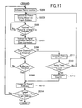
- FIG. 8 shows a flowchart of the retry routine by the retry controlling means 118 forming of part of the reproduction apparatus 140.
- the retry controlling means 118 then initializes the retry counter indicative of the retry times in step S204.
- the pickup driving means 117 is then instructed by the retry controlling means 118 to have the optical pickup 112 move to the target address on the optical disc 111 to reproduce the digital information in step S205.
- the retry controlling means 118 is operated to confirm whether or not the pickup driving means 117 is finished with the optical pickup 112 moved to the target address in step S206.
- the signal outputted from the optical pickup 112 is inputted to the signal amplifying means 113 where the signal is amplified.
- the pickup driving means 117 is again instructed by the retry controlling means 118 to have the optical pickup 112 move to the target address on the optical disc 111 to reproduce the digital information in step S205.
- the signal amplified by the signal amplifying means 113 is fed to the signal processing means 114 for performing the error correction process.
- the signal processing means 114 is then instructed by the retry controlling means 118 to correct errors contained in the digital information on the optical disc 111 in step S207.
- the retry controlling means 118 is then operated to confirm whether or not the error correction process is successfully performed by the signal processing means 114 in step S208.
- the signal processed by the signal processing means 114 is fed to the buffer memory 115 by the signal processing means 114.
- the retry counter is incremented by the retry controlling means 118 in step S211.
- the retry controlling means 118 is then operated to judge whether or not the retry times exceed the upper limit times through the indication of the retry counter in step S212. If the retry times do not exceed the upper limit times, the retry controlling means 118 has the optical pickup 112 continue retrying to read the digital information at the same target address until the optical pickup 112 obtains the recorded digital information on the optical disc 111 after returning to step S205.
- the retry controlling means 118 is operated to initialize the retry counter in step S213.
- the upper limit times to be changed based on the amount of residue digital information remaining in the buffer memory 115 leads to the fact that the video and audio signals can continuously be decoded without being under the frozen state.
- the retry controlling means 118 is then operated to confirm whether or not the signal outputted from the signal processing means 114 is completed to be stored in the buffer memory 115 by the signal processing means 114 in step S209.
- the retry controlling means 118 is operated to replace the current target address with a new target address to obtain the next digital information on the optical disc 111 in step S210.
- the retry controlling means 118 then initializes the DSI reference counter in step S401.
- the signal outputted from the signal amplifying means 113 fails to be stored in the buffer memory 115 by the signal processing means 114 in step S209, the signal outputted from the signal amplifying means 113 is again fed to the buffer memory 115 and stored in the buffer memory 115 by the signal processing means 114 until the electric signal is completely stored in the buffer memory 115.
- the retry controlling means 118 is then operated to judge whether or not the optical pickup 112 finishes reading the digital information at the final target address of the optical disc 111 in step S214. If the optical pickup 112 finishes reading the digital information at the final target address of the optical disc 111 in step S214, the retry controlling means 118 is operated to stop the retry routine. If, on the other hand, the optical pickup 112 has not finished reading the digital information at the final target address of the optical disc 111 in step S214, the process returns to the step S201.
- the retry driving means 117 is operated to have the optical pickup 112 to skip the current target address and move to a next target address. If the digital information on the optical disc 111 is encoded by the MPEG standard, the next address is set the first address defined for the GOP unit by the retry controlling means 118 to minimize the video disturbance.
- the reference counter of the DSI is initialized by the retry controlling means 118 after each reading the digital information in step S401.
- the reproduction apparatus 140 is operated to obtain the first address defined for the GOP unit after referring to the DSI in the navigation pack according to the number of the reference counter of the DSI in step S402.
- the retry controlling means 118 is operated to replace the current target address with an address stored in "FWDI Next" of FIG. 7 in step S403.
- the address stored in "FWDI Next” shows the first address defined for the GOP unit nearest to the current address.
- the number of the reference counter of the DSI is then "1" submitted by the retry controlling means 118 in the step S404.
- the retry controlling means 118 is operated to replace the current target address with an address stored in "FWDI 5" of FIG. 7 in step S405.
- the retry controlling means 118 is operated to set the address stored in "FWDI 10" at the target address in step S407.
- the number of the reference counter of the DSI is then "0" substituted by the retry controlling means 118 in step S408.
- the target address is gradually replaced with the first address defined for the GOP unit by the retry controlling means 118.
- the pickup driving means 117 is then operated to have the optical pickup 112 move the next address indicated by the retry controlling means 118.
- the error correction for the video and audio information recorded on the optical disc 111 is performed with the upper limit times to be changed based on the first address defined for the GOP unit of the DSL This makes it possible to continuously decode video and audio signals without being under the frozen state.
- the first embodiment of the reproduction apparatus according to the present invention previously mentioned may be replaced by the fourth embodiment of the reproduction apparatus according to the present invention which will be described hereinafter.
- the elements and parts of the fourth embodiment of the reproduction apparatus 150 are entirely the same as those of the third embodiment of the reproduction apparatus 140 according to the present invention as shown in FIG. 6 except for the elements and parts. Therefore, only the elements and parts of the fourth embodiment of the reproduction apparatus 150 different from those of the third embodiment of the reproduction apparatus 140 will be described in detail hereinafter, but the elements and parts of the third embodiment of the reproduction apparatus 140 entirely the same as those of the third embodiment of the reproduction apparatus 140 bear the same reference numerals as those of the third embodiment of the reproduction apparatus 140 in FIG. 6.
- the reproduction apparatus 150 has the digital information having a video title set information and a plurality of groups of picture unit.
- the video title set information includes a video title set time map having a first address.
- the reproduction apparatus 150 further comprises retry controlling means 118.
- the retry controlling means 118 is designed to control the times of retry routine based on the video title set time map.
- the retry controlling means 118 has a reference counter of the video title set information.
- the reference counter of the video title set time map has a number referred by the retry controlling means 118 by which the optical pickup is moved to the target address according to the first address of the video title set time map of the video title set information.
- the reproduction apparatus 150 is operated to use the optical discs having the video data recorded and defined under the DVD-Video format planed by the DVD Forum.
- the above video data consists of the video title set information, hereinafter simply referred to as "VTSI".
- the video title set information includes the video title set time map, hereinafter simply referred to as "VTSTM", with the information of the time search function.
- VTSI has controlling information for video reproduction.
- the VTSTM is a useful data recorded in the VTSI for performing the time search function.
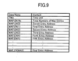
- the list of the VTSTM is shown FIG. 9 and contains data name and contents corresponding to the data name.
- the VTSTM shown in FIG. 9 is referred to the time search function.
- the VTSTM includes a time unit, appearing with the legend "TMU” in FIG. 9, and showing the time difference between two given entry addresses, a map entry number, appearing with the legend "MAP_EN_Ns” in FIG. 9, and showing a sum of entry numbers, and a plural of map entries, appearing with the legend "MAP_EN” in FIG. 9, recorded in series on the optical disc 111.
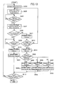
- FIG. 10 shows a flowchart of the retry routine controlled by the retry controlling means 118 forming of part of the reproduction apparatus 150.
- the retry controlling means 118 initializes the retry counter indicative of the retry times in step S204.
- the pickup driving means 117 is then instructed by the retry controlling means 118 to have the optical pickup 112 move to the target address on the optical disc 111 to reproduce the digital information in step S205.
- the retry controlling means 118 is operated to confirm whether or not the pickup driving means 117 is finished with the optical pickup 112 moved to the target address in step S206.
- the signal outputted from the optical pickup 112 is inputted to the signal amplifying means 113 where the signal is amplified.
- the pickup driving means 117 is again instructed by the retry controlling means 118 to have the optical pickup 112 move to the target address on the optical disc 111 to reproduce the digital information in step S205.
- the signal amplified by the signal amplifying means 113 is fed to the signal processing means 114 for performing the error correction process.
- the signal processing means 114 is then instructed by the retry controlling means 118 to correct errors contained in the digital information on the optical disc 111 in step S207.
- the retry controlling means 118 is then operated to confirm whether or not the error correction process is successfully performed by the signal processing means 114 in step S208.
- the signal processed by the signal processing means 114 is fed to the buffer memory 115 by the signal processing means 114.
- the retry counter is incremented by the retry controlling means 118 in step S211.
- the retry controlling means 118 is then operated to judge whether or not the retry times exceed the upper limit times through the indication of the retry counter in step S212. If the retry times do not exceed the upper limit times, the retry controlling means 118 has the optical pickup 112 continue retrying to read the digital information at the same target address until the optical pickup 112 obtains the recorded digital information on the optical disc 111 after returning to step S205.
- the retry controlling means 118 is operated to initialize the retry counter in step S213.
- the upper limit times to be changed based on the amount of residue digital information remaining in the buffer memory 115 leads to the fact that the video and audio signals can continuously be decoded without being under the frozen state.
- the retry controlling means 118 is then operated to confirm whether or not the signal outputted from the signal processing means 114 is completed to be stored in the buffer memory 115 by the signal processing means 114 in step S209.
- the retry controlling means 118 is operated to replace the current target address with a new target address to obtain the next digital information on the optical disc 111 in step S210.
- the retry controlling means 118 then initializes the VTSTM reference counter in step S501.
- the signal outputted from the signal amplifying means 113 fails to be stored in the buffer memory 115 by the signal processing means 114 in step S209, the signal outputted from the signal amplifying means 113 is again fed to the buffer memory 115 and stored in the buffer memory 115 by the signal processing means 114 until the electric signal is completely stored in the buffer memory 115.
- the retry controlling means 118 is then operated to judge whether or not the optical pickup 112 finishes reading the digital information at the final target address of the optical disc 111 in step S214. If the optical pickup 112 finishes reading the digital information at the final target address of the optical disc 111 in step S214, the retry controlling means 118 is operated to stop the retry routine. If, on the other hand, the optical pickup 112 has not finished reading the digital information at the final target address of the optical disc 111 in step S214, the process returns to the step S201.
- the retry driving means 117 is operated to have the optical pickup 112 to skip the current target address for moving to a next target address. If the digital information on the optical disc 111 is encoded by the MPEG standard, the next address is set the first address defined for the GOP unit by the retry controlling means 118 for minimizing the video disturbance.
- the reference counter of the VTSTM in the VTSI is initialized by the retry controlling means 118 after each reading the digital information in step S501.
- the reproduction apparatus 150 is then operated to obtain the first address defined for the GOP unit after referring to the VTSTM in the VTSI according to the number of the reference counter of the VTSTM in step S502.
- the retry controlling means 118 is operated to replace the current target address with an address stored in "MAP_EN" which shows an address of 1 second after the current address in step S503.
- the number of the reference counter of the VTSTM is then submitted "1" by the retry controlling means 118 in the step S504.
- the retry controlling means 118 When the number of the reference counter of the VTSTM is "1" in step S502, the retry controlling means 118 is operated to replace the current target address with an address stored in "MAP_EN" which shows an address of 5 seconds after the current address in step S505. The number of the reference counter of the VTSTM is then submitted “2" by the retry controlling means 118 in the step S506.
- the retry controlling means 118 is operated to replace the current target address with an address stored in "MAP_EN" which shows an address of 10 seconds after the current address in step S507.
- the number of the reference counter of the VTSTM is then submitted "0" by the retry controlling means 118 in the step S508.
- the target address is gradually replaced with the first address defined for the GOP unit by the retry controlling means 118.
- the pickup driving means 117 is then operated to have the optical pickup 112 move the next address indicated by the retry controlling means 118.
- the error correction for the video and audio information recorded on the optical disc 111 is performed with the upper limit times to be changed based on the first address defined for the GOP unit of the VTSTM. This makes it possible to continuously decode video and audio signals without being under the frozen state.
- the VTSI is recorded in the controlling area which is out of the area of the vide and audio signals area on the optical disc 111.
- the reading out the VTSI results in the fact that the addresses damaged by the external damages are certainly skipped by the retry controlling means 118 through the first address defined for the GOP unit of the VTSTM of the VTSI.
- the first embodiment of the reproduction apparatus according to the present invention previously mentioned may be replaced by the fifth embodiment of the reproduction apparatus according to the present invention which will be described hereinafter.
- FIG. 11 of the drawings there is shown a block diagram of the fifth preferred embodiment of the reproduction apparatus 160 according to the present invention.
- the elements and parts of the fifth embodiment of the reproduction apparatus 160 according to the present invention as shown in FIG. 11 are entirely the same as those of the first embodiment of the reproduction apparatus 110 according to the present invention as shown in FIG. 1 except for the elements and parts. Therefore, only the elements and parts of the fifth embodiment of the reproduction apparatus 160 different from those of the first embodiment of the reproduction apparatus 110 will be described in detail hereinafter, but the elements and parts of the fifth embodiment of the reproduction apparatus 160 entirely the same as those of the first embodiment of the reproduction apparatus 110 bear the same reference numerals as those of the first embodiment of the reproduction apparatus 110 in FIG. 1.
- the reproduction apparatus 160 further comprises external damage detecting means 151 and retry controlling means 118.
- the external damage detecting means 151 is designed to detect external damages on the surface of the optical disc 111.
- the retry controlling means 118 is adapted to control the times of retry routines based on the external damages detected by the external damage detecting means 151.
- the times of retry routines are repeated by a first retry time at a first address with the external damages and by a second routine time at a second address without the external damages, the first time is smaller than the second time.
- the reproduction apparatus 160 further comprises first external damage registration means 152 and a registering addresses means 153.
- the first external damage registration means 152 is designed to register the addresses with external damages of the optical disc 111.
- the registering addresses means 153 is adapted to store the addresses with damages are registered by the retry controlling means 118.
- the reproduction apparatus 160 further comprises second external damage registration means 154.
- the second external damage registration means 154 designed to be constituted by a nonvolatile memory adapted to hold the digital information after the reproducing apparatus 160 is out of power.
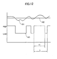
- FIG. 12 shows a detection waveform 161, a comparator criterion level 162, and a pulse waveform from comparator 155.
- the detection waveform 161 is obtained by a detector with a predetermined time constant of a detecting electric circuit after applying the reproducing signal to input terminals of the external damage detecting means 151 in FIG. 12.
- the external damages on the surface of the optical disc 111 result in reducing the outputted level of the optical pickup 112 as well as the direct current outputted level of the detection waveform 161.
- the reproduction apparatus further comprises a comparator 155 operative to compare the direct current outputted level of the detection waveform 161 with the comparator criterion level 162, and signal processing means 114 designed to judge on the basis of the compared results obtained by the comparator 155 on whether or not the outputted level of the optical pickup 112 is lowered under the influence of the external damages.
- the pulse waveform 163 is obtained by the comparator 155 which is adapted to compare the detection waveform 161 with the comparator criterion level 162. It is a high possibility that the optical disc 111 has external damages on the range corresponding to the low level range of the pulse waveform from the comparator 155 in FIG. 12.
- external damage detecting means 151 is operated to judge whether or not the external damages exist at the current target address through a duty ratio shown in FIG. 12 as t1/t determined by calculation from the pulse waveform from comparator 155.
- FIG. 13 shows a flowchart of the retry routine controlled by the retry controlling means 118 forming of part of the reproduction apparatus 160.
- the retry controlling means 118 firstly initializes the retry counter indicative of the retry times in step S204.
- the pickup driving means 117 is then instructed by the retry controlling means 118 to have the optical pickup 112 move to the target address on the optical disc 111 to reproduce the digital information in step S205.
- the retry controlling means 118 is operated to confirm whether or not the pickup driving means 117 is finished with the optical pickup 112 moved to the target address in step S206.
- the signal outputted from the optical pickup 112 is inputted to the signal amplifying means 113 where the signal is amplified.
- the pickup driving means 117 is again instructed by the retry controlling means 118 to have the optical pickup 112 move to the target address on the optical disc 111 to reproduce the digital information in step S205.
- the signal amplified by the signal amplifying means 113 is fed to the signal processing means 114 for performing the error correction process.
- the signal processing means 114 is then instructed by the retry controlling means 118 to correct errors contained in the digital information on the optical disc 111 in step S207.
- the retry controlling means 118 is then operated to confirm whether or not the error correction process is successfully performed by the signal processing means 114 in step S208.
- the signal processed by the signal processing means 114 is fed to the buffer memory 115 by the signal processing means 114.
- the external damage detecting means 151 is then operated to judge whether or not the external damages exist at the current address on the surface of the optical disc 111 in step S601.
- the retry controlling means 118 is operated to have a retry upper limit times set to a first number in step S602.
- the retry controlling means 118 is in turn operated to have the retry upper limit times set to a second number, which is smaller than the first number, in step S603.
- the retry counter is then incremented by the retry controlling means 118 in step S211.
- the retry controlling means 118 is then operated to judge whether or not the retry times exceed the upper limit times through the indication of the retry counter in step S212. If the retry times don not exceed the upper limit times, the retry controlling means 118 has the optical pickup 112 continue retrying to read the digital information at the same target address until the optical pickup 112 obtains the recorded digital information on the optical disc 111 after returning to step S205. If the retry times exceed the upper limit times, the retry controlling means 118 is operated to initialize the retry counter in step S213. The upper limit times to be changed based on the external damages at the current address on the optical disc 111 leads to the fact that the video and audio signals can continuously be decoded without being under the frozen state.
- the error correction for the video and audio information recorded on the optical disc 111 is performed with the upper limit times to be changed based on the external damages at the current address on the optical disc 111 by the first embodiment of the reproduction apparatus 110 according to the present invention. This makes it possible to continuously decode video and audio signals without being under the frozen state.
- the upper limit times of retry routine can be changed before the reproducing the video and audio signals.
- the second external damage registration means 154 designed to be constituted by a nonvolatile memory makes it possible to change the upper limit times of retry routine after the reproducing apparatus 160 is once out of power.
- the first embodiment of the reproduction apparatus according to the present invention previously mentioned may be replaced by the sixth embodiment of the reproduction apparatus according to the present invention which will be described hereinafter.
- FIG. 14 of the drawings there is shown a block diagram of the sixth preferred embodiment of the reproduction apparatus 170 according to the present invention which comprises an optical pickup 112 and signal amplifying means 113.
- the optical pickup 112 is movable in the radial direction of the optical disc 111 to assume radial positions to read the digital information converted into electric signals.
- the digital information contains errors appearing when the digital information is read by the optical pickup 112.
- the signal amplifying means 113 is operative to amplify the electric signals converted from the digital information read by the optical pickup 112.
- the reproduction apparatus 170 further comprises signal processing means 114 and a buffer memory 115.
- the signal processing means 114 is designed to process the electric signals in one or more times of retry routines to correct the errors outputted as the electric signals from the signal amplifying means 113.
- the buffer memory 115 is operative to store the electric signals outputted from the signal processing means 114.
- the reproduction apparatus 170 further comprises signal decoding means 116 and pickup driving means 117.
- the signal decoding means 116 is adapted to decode the electric signals stored in the buffer memory 115 and outputted from the buffer memory 115.
- the pickup driving means 117 is operative to drive the optical pickup 112 to move on the optical disc 111. The errors are associated with respective addresses to be targeted by the optical pickup 112 when the optical pickup 112 is moved by the pickup driving means 117.
- the reproduction apparatus 170 further comprises radial position detecting means 172 and retry controlling means 118.
- the radial position detecting means 172 is designed to detect the radial positions of the optical pickup 112.
- the retry controlling means 118 is adapted to control the times of retry routines based on the radial position of the optical pickup 112 detected by the radial position detecting means 172.
- the retry controlling means 118 has a retry counter indicative of the retry times and an upper limit times by which the retry routine is repeated.
- FIG. 15 shows a flowchart of the retry routine controlled by the retry controlling means 118 forming of part of the reproduction apparatus 170.
- the retry controlling means 118 is operable to perform a comparison of a predetermined criterion circumferential track and a current circumferential track on the optical disc 111 in step S701.
- the retry controlling means 118 sets a retry upper limit times to a first number in step S202.
- the retry controlling means 118 sets a retry upper limit times to a second number, which is smaller than the first number, in step S203.
- the retry controlling means 118 then initializes the retry counter indicative of the retry times in step S204.
- the pickup driving means 117 is then instructed by the retry controlling means 118 to have the optical pickup 112 move to the target address on the optical disc 111 to reproduce the digital information in step S205.
- the retry controlling means 118 is operated to confirm whether or not the pickup driving means 117 is finished with the optical pickup 112 moved to the target address in step S206.
- the signal outputted from the optical pickup 112 is inputted to the signal amplifying means 113 where the signal is amplified.
- the pickup driving means 117 is again instructed by the retry controlling means 118 to have the optical pickup 112 move to the target address on the optical disc 111 to reproduce the digital information in step S205.
- the signal amplified by the signal amplifying means 113 is fed to the signal processing means 114 for performing the error correction process.
- the signal processing means 114 is then instructed by the retry controlling means 118 to correct errors contained in the digital information on the optical disc 111 in step S207.
- the retry controlling means 118 is then operated to confirm whether or not the error correction process is successfully performed by the signal processing means 114 in step S208.
- the signal processed by the signal processing means 114 is fed to the buffer memory 115 by the signal processing means 114.
- the retry counter is incremented by the retry controlling means 118 in step S211.
- the retry controlling means 118 is then operated to judge whether or not the retry times exceed the upper limit times through the indication of the retry counter in step S212. If the retry times exceed the upper limit times, the retry controlling means 118 has the optical pickup 112 continue retrying to read the digital information at the same target address until the optical pickup 112 obtains the recorded digital information on the optical disc 111 after returning to step S205.
- the retry controlling means 118 is operated to initialize the retry counter in step S213.
- the upper limit times to be changed based on the radial position of the optical pickup 112 leads to the fact that the video and audio signals can continuously be decoded without being under the frozen state.
- the retry controlling means 118 is then operated to confirm whether or not the signal outputted from the signal processing means 114 is completed to be stored in the buffer memory 115 by the signal processing means 114 in step S209.
- the retry controlling means 118 is operated to replace the current target address with a new target address to obtain the next digital information on the optical disc 111 in step S210.
- the signal outputted from the signal amplifying means 113 fails to be stored in the buffer memory 115 by the signal processing means 114 in step S209, the signal outputted from the signal amplifying means 113 is again fed to the buffer memory 115 and stored in the buffer memory 115 by the signal processing means 114 until the electric signal is completely stored in the buffer memory 115.
- the retry controlling means 118 is then operated to judge whether or not the optical pickup 112 finishes reading the digital information at the final target address of the optical disc 111 in step S214. If the optical pickup 112 finishes reading the digital information at the final target address of the optical disc 111 in step S214, the retry controlling means 118 is operated to stop the retry routine. If, on the other hand, the optical pickup 112 has not finished reading the digital information at the final target address of the optical disc 111 in step S214, the process returns to the step S201.
- the error correction for the video and audio information recorded on the optical disc 111 is performed with the upper limit times to be changed based on the radial position of the optical pickup 112 by the sixth embodiment of the reproduction apparatus 170 according to the present invention. This makes it possible to continuously decode video and audio signals without being under the frozen state.
Landscapes
- Engineering & Computer Science (AREA)
- Signal Processing (AREA)
- Optical Recording Or Reproduction (AREA)
- Television Signal Processing For Recording (AREA)
- Signal Processing For Digital Recording And Reproducing (AREA)
Applications Claiming Priority (2)
| Application Number | Priority Date | Filing Date | Title |
|---|---|---|---|
| JP2000334889 | 2000-11-01 | ||
| JP2000334889A JP2002140875A (ja) | 2000-11-01 | 2000-11-01 | ディスク再生装置およびディスク読み出し方法 |
Publications (2)
| Publication Number | Publication Date |
|---|---|
| EP1204112A2 true EP1204112A2 (de) | 2002-05-08 |
| EP1204112A3 EP1204112A3 (de) | 2007-01-10 |
Family
ID=18810724
Family Applications (1)
| Application Number | Title | Priority Date | Filing Date |
|---|---|---|---|
| EP01125383A Withdrawn EP1204112A3 (de) | 2000-11-01 | 2001-10-30 | Ein Wiedergabegerät und Verfahren zur Wiedergabe von auf einer optischen Platte aufgezeichneten digitalen Informationen |
Country Status (5)
| Country | Link |
|---|---|
| US (1) | US20020064379A1 (de) |
| EP (1) | EP1204112A3 (de) |
| JP (1) | JP2002140875A (de) |
| CN (1) | CN1365114A (de) |
| HK (1) | HK1046581A1 (de) |
Cited By (1)
| Publication number | Priority date | Publication date | Assignee | Title |
|---|---|---|---|---|
| EP2265030A3 (de) * | 2009-06-15 | 2013-11-27 | Funai Electric Co., Ltd. | Wiedergabesystem für Bewegtbilder |
Families Citing this family (9)
| Publication number | Priority date | Publication date | Assignee | Title |
|---|---|---|---|---|
| JP2005251276A (ja) * | 2004-03-03 | 2005-09-15 | Ricoh Co Ltd | 情報記録再生装置と情報記録再生方法 |
| JP4685734B2 (ja) * | 2006-09-01 | 2011-05-18 | ヒタチグローバルストレージテクノロジーズネザーランドビーブイ | 磁気ヘッドスライダの製造方法 |
| WO2008056424A1 (en) * | 2006-11-10 | 2008-05-15 | Pioneer Corporation | Streaming data reproduction program and optical disc drive device |
| JP2009211773A (ja) * | 2008-03-05 | 2009-09-17 | Funai Electric Co Ltd | 光ディスク再生装置及び光ディスクの再生方法 |
| JP4752898B2 (ja) * | 2008-11-14 | 2011-08-17 | オンキヨー株式会社 | コンテンツ配信システム、受信装置及び再生プログラム |
| US9531646B1 (en) | 2009-12-07 | 2016-12-27 | Altera Corporation | Multi-protocol configurable transceiver including configurable deskew in an integrated circuit |
| CN104113778B (zh) * | 2014-08-01 | 2018-04-03 | 广州猎豹网络科技有限公司 | 一种视频流解码方法及装置 |
| CN106547635B (zh) * | 2015-09-18 | 2020-10-09 | 阿里巴巴集团控股有限公司 | 一种作业的操作重试方法和装置 |
| US9653111B1 (en) * | 2015-11-23 | 2017-05-16 | Avago Technologies General Ip (Singapore) Pte. Ltd. | Track quality classifier |
Family Cites Families (14)
| Publication number | Priority date | Publication date | Assignee | Title |
|---|---|---|---|---|
| EP0248536B1 (de) * | 1986-05-31 | 1992-07-22 | Sony Corporation | Methoden und Gerät zum Suchen einer Zieladresse auf einem Aufzeichnungsmedium |
| JPH07312039A (ja) * | 1994-05-19 | 1995-11-28 | Matsushita Electric Ind Co Ltd | ディスク装置 |
| JPH08273283A (ja) * | 1995-03-28 | 1996-10-18 | Sharp Corp | データ再生装置 |
| TW329587B (en) * | 1996-02-08 | 1998-04-11 | Matsushita Electric Industrial Co Ltd | Television receiver, data recording method and data replaying method |
| JPH10188495A (ja) * | 1996-12-24 | 1998-07-21 | Toshiba Corp | ディスク再生装置 |
| DE69805563T2 (de) * | 1997-03-19 | 2003-01-16 | Kabushiki Kaisha Toshiba, Kawasaki | Ein Plattengerät mit einem einzelnen Aufnahmekopf fähig zum gleichzeitigen Aufnehmen und Wiedergeben |
| JPH11195277A (ja) * | 1997-12-26 | 1999-07-21 | Victor Co Of Japan Ltd | 光記録媒体再生装置及び光記録媒体再生方法 |
| US6587641B1 (en) * | 1998-07-21 | 2003-07-01 | Matsushita Electric Industrial Co., Ltd. | Apparatus for simultaneously writing and outputting data stream |
| JP2000100087A (ja) * | 1998-09-18 | 2000-04-07 | Sony Corp | 情報再生装置、情報再生方法、情報記録装置及び情報記録方法 |
| JP3975586B2 (ja) * | 1998-11-11 | 2007-09-12 | ソニー株式会社 | 記録再生装置および方法、並びにプログラム記録媒体 |
| JP2000195144A (ja) * | 1998-12-25 | 2000-07-14 | Sony Corp | 記録媒体駆動装置および方法、情報記録再生システムおよび方法、並びに提供媒体 |
| JP2000276857A (ja) * | 1999-03-24 | 2000-10-06 | Sony Corp | データ記録装置及びデータ記録方法並びにデータ再生装置及びデータ再生方法 |
| US6690882B1 (en) * | 1999-09-27 | 2004-02-10 | Western Digital Technologies, Inc. | Method of operating a disk drive for reading and writing audiovisual data on an urgent basis |
| JP2001211405A (ja) * | 1999-11-16 | 2001-08-03 | Sony Corp | データ再生装置及び方法 |
-
2000
- 2000-11-01 JP JP2000334889A patent/JP2002140875A/ja active Pending
-
2001
- 2001-10-29 US US10/045,362 patent/US20020064379A1/en not_active Abandoned
- 2001-10-30 EP EP01125383A patent/EP1204112A3/de not_active Withdrawn
- 2001-11-01 CN CN01145643A patent/CN1365114A/zh active Pending
-
2002
- 2002-11-04 HK HK02108001.8A patent/HK1046581A1/zh unknown
Cited By (1)
| Publication number | Priority date | Publication date | Assignee | Title |
|---|---|---|---|---|
| EP2265030A3 (de) * | 2009-06-15 | 2013-11-27 | Funai Electric Co., Ltd. | Wiedergabesystem für Bewegtbilder |
Also Published As
| Publication number | Publication date |
|---|---|
| CN1365114A (zh) | 2002-08-21 |
| HK1046581A1 (zh) | 2003-01-17 |
| JP2002140875A (ja) | 2002-05-17 |
| US20020064379A1 (en) | 2002-05-30 |
| EP1204112A3 (de) | 2007-01-10 |
Similar Documents
| Publication | Publication Date | Title |
|---|---|---|
| KR100717102B1 (ko) | Bca 데이터 재생 방법 | |
| CN100485803C (zh) | 光盘重放方法 | |
| EP0837472B1 (de) | Signalaufzeichnungsgerät und -verfahren | |
| US7555200B2 (en) | Recording medium having a data structure for managing a data stream recorded on the recording medium and recording and reproducing methods and apparatuses | |
| US7805062B2 (en) | Transmitting and recording method, reproducing method, and reproducing apparatus of information and its recording medium | |
| EP1204112A2 (de) | Ein Wiedergabegerät und Verfahren zur Wiedergabe von auf einer optischen Platte aufgezeichneten digitalen Informationen | |
| KR19980065239A (ko) | 광디스크의 재생시간 산출장치 및 방법 | |
| KR100189534B1 (ko) | 비트 에러레이트를 이용한 디지탈 영상기록 재생장치의 트랙킹 제어회로 및 그 제어방법 | |
| KR100254612B1 (ko) | 광디스크 재생장치의 가변전송레이트 버퍼 관리장치 및 그 제어방법 | |
| US5325364A (en) | Method for error correction and circuit for realizing same | |
| JPH05109205A (ja) | デイスク記録および再生装置 | |
| US7257068B2 (en) | Apparatus and method for reproducing replacement data recorded on a disc | |
| US9330716B2 (en) | Apparatus and a record carrier for, and a method of recording a sequence of video data signals | |
| KR100554783B1 (ko) | 디지털 데이터 스트림의 변속재생 정보 기록장치 및 방법과, 이를 이용한 재생장치 및 방법 | |
| JP2001189912A (ja) | デジタルtv放送記録再生装置 | |
| US9779776B1 (en) | Optical disk reproducing device, reproducing circuit of the same, and reproducing method of optical disk | |
| KR100242133B1 (ko) | 외란에 대하여 강인성을 갖는 심리스(seamless) 재생방법 | |
| JP2005174403A (ja) | データ再生装置及び光ディスク再生装置 | |
| JPH08279993A (ja) | ディジタル信号再生装置 | |
| JP2003163874A (ja) | 記録媒体、画像データ再生装置、画像データ記録方法、および、画像データ再生方法 | |
| JP2002109827A (ja) | データ再生装置およびディスクメディア再生装置 | |
| JPH0294073A (ja) | エラー検出装置 | |
| WO2004051659A1 (en) | Editing of data frames | |
| JP2001297526A (ja) | 記録装置、再生装置、記録再生装置、及び記録又は再生方法 | |
| JPH10326466A (ja) | 媒体読み取り装置 |
Legal Events
| Date | Code | Title | Description |
|---|---|---|---|
| PUAI | Public reference made under article 153(3) epc to a published international application that has entered the european phase |
Free format text: ORIGINAL CODE: 0009012 |
|
| AK | Designated contracting states |
Kind code of ref document: A2 Designated state(s): AT BE CH CY DE DK ES FI FR GB GR IE IT LI LU MC NL PT SE TR |
|
| AX | Request for extension of the european patent |
Free format text: AL;LT;LV;MK;RO;SI |
|
| RIC1 | Information provided on ipc code assigned before grant |
Ipc: G11B 19/04 20060101ALI20060809BHEP Ipc: G11B 27/36 20060101ALI20060809BHEP Ipc: G11B 20/18 20060101AFI20060809BHEP |
|
| PUAL | Search report despatched |
Free format text: ORIGINAL CODE: 0009013 |
|
| AK | Designated contracting states |
Kind code of ref document: A3 Designated state(s): AT BE CH CY DE DK ES FI FR GB GR IE IT LI LU MC NL PT SE TR |
|
| AX | Request for extension of the european patent |
Extension state: AL LT LV MK RO SI |
|
| 17P | Request for examination filed |
Effective date: 20070214 |
|
| AKX | Designation fees paid |
Designated state(s): DE GB |
|
| STAA | Information on the status of an ep patent application or granted ep patent |
Free format text: STATUS: THE APPLICATION HAS BEEN WITHDRAWN |
|
| 18W | Application withdrawn |
Effective date: 20070830 |