EP1204192A2 - Befestigungsvorrichtung für Elektromotoren, insbesondere Spaltpolmotoren - Google Patents
Befestigungsvorrichtung für Elektromotoren, insbesondere Spaltpolmotoren Download PDFInfo
- Publication number
- EP1204192A2 EP1204192A2 EP01114081A EP01114081A EP1204192A2 EP 1204192 A2 EP1204192 A2 EP 1204192A2 EP 01114081 A EP01114081 A EP 01114081A EP 01114081 A EP01114081 A EP 01114081A EP 1204192 A2 EP1204192 A2 EP 1204192A2
- Authority
- EP
- European Patent Office
- Prior art keywords
- fastening
- leg
- openings
- fastening device
- longitudinal direction
- Prior art date
- Legal status (The legal status is an assumption and is not a legal conclusion. Google has not performed a legal analysis and makes no representation as to the accuracy of the status listed.)
- Granted
Links
Images

Classifications
-
- H—ELECTRICITY
- H02—GENERATION; CONVERSION OR DISTRIBUTION OF ELECTRIC POWER
- H02K—DYNAMO-ELECTRIC MACHINES
- H02K5/00—Casings; Enclosures; Supports
- H02K5/26—Means for adjusting casings relative to their supports
Definitions
- the invention relates to a fastening device for electric motors, especially for shaded-pole motors, in the manner of a bracket for attachment to a bracket, e.g. on a stand.
- the invention has for its object a fastening device for Electric motors, especially for shaded-pole motors, to create the Attaching the electric motor to a bracket, e.g. in the form of a pedestal, essential with different dimensions and other conditions simplified, without it being absolutely necessary, on the motor side take appropriate precautions.
- the task is with a fastening device of the type mentioned according to the invention solved by the features in claim 1.
- This Fastening device allows when attaching an electric motor to a Bracket e.g. in the form of a pedestal, the consideration of different Hole spacing and similar space conditions without this already engine side must be taken into account with particularly high effort.
- the Fastening device represents an adapter that is between the electric motor and the holder an adaptation to the most varied dimensions and Conditions.
- a fastening device 10 which for the Attachment of an electric motor 11, e.g. a shaded-pole motor, one electronically commutated permanent magnet motors (PM-EC motors) or the like, serves on a bracket 14, by means of which the attachment then only to any 4 schematically indicated part 9 happens.
- the electric motor 11 has a motor housing 12 only indicated schematically there with a visible, on the right side of this attached end plate 13.
- One on the left side of the motor housing 12 is also present end shield not visible.
- the bearing end shield 13 is on the remaining part of the motor housing 12 e.g. screwed by means of screws 41.
- the screws 41 can not from shown a bearing end plate up to the visible other end plate 13th reach through and both with the remaining part of the motor housing 12th connect.
- the bracket 14 by means of which the attachment of the electric motor 11 any part 9 happens by means of indicated screws 42 lies as finished Component. It consists of a base 15, which is approximately U-shaped and an upper leg 16 forming the U-base and two of them striving bilateral and spaced side legs 18, each end of which has an outwardly bent lower one Leg 17 with an elongated hole 23 contained therein for each penetration a screw 42.
- the fastening device 10 is on the electric motor 11, in particular on End shield 13, attached using the existing screws 41 and serves as an adapter for attaching the electric motor 11 to the bracket 14.
- the bracket 14 has predetermined dimensions and in the upper leg 16 four holes, two each in the longitudinal direction of the upper Leg 16 considered pair with a predetermined distance of 18 mm once and on the other form from 26 mm.
- the electric motor 11 with attached Fastening device 10 is on the bracket 14, in particular the Stand 15, by means of fastening means 26, in particular fastening screws, attached, one of the existing in the upper leg 16 Push through pairs of holes.
- the fastening device 10 has a support leg 19 and one of them about right-angled struts 24, the several Through openings 25 for the passage of the fastening leg 24 attacking fasteners 26, in particular fastening screws, having.
- the through openings 25 through which the two fastening means 26 pass through one in the longitudinal direction of the fastening leg 24 measured distance of 18 mm from each other, measured from the center Through opening 25 to the middle of through opening 25 upper leg 16 of the base 15 another, e.g.
- the fastening leg 24 has four rows 27, 28 directed transversely thereto and 29, 30 of such through openings 25, two of which Rows 27, 29, viewed in the longitudinal direction of the fastening leg 24, one have a smaller distance from one another than the other two rows 28, 29.
- the row spacing is 18 mm and in the second case 26 mm, each viewed in the longitudinal direction of the fastening leg 24.
- Each of the four rows 27 to 30 has three in the embodiment shown Through openings 25. Instead, it can do more or less his.
- the number of through openings 25 per row increases the variability the attachment of the electric motor 11 transverse to the longitudinal course of the upper one Leg 16 of the pedestal 15 considered.
- the multitude of Through openings 25 per row 27 to 30 thus make it possible to have outer other environmental conditions when attaching the electric motor 11 to consider.
- the fastening leg 24 also has at least one slot 31, which extends in the transverse direction of the fastening leg 24.
- the slot 31 is in the middle between the rows 27 running at a distance on both sides thereof, 28 and 29, 30 of through openings 25 are arranged.
- the slot 31 runs approximately parallel to the respective rows 27 to 30 and has a length e.g. of at least 22 mm.
- the elongated hole 31 makes an attachment of the Electric motor 11 on the bracket 14, in particular the base 15, e.g. in possible in such a way that the two fastening means 26, in particular Fixing screws, instead of in the embodiment shown Push through slot 31, the longitudinal center axis of the electric motor 11 being approximately runs parallel to the upper leg 16 of the base 15 and not, as in shown embodiment, transverse to it.
- the fastening device 10 is designed so that the area of the Mounting leg 24, the through holes 25 and / or that has at least one slot 31 as an approximately box-shaped central part 32 is designed such that through the through openings 25 and at least one fastening means 26 extending through slot 31, in particular fastening screws, with their heads 33 inside the box are receivable and not over the top of the fastening leg 24 survive disturbing.
- this design offers an approximately box-shaped design Middle part 32 the possibility of forming corresponding edge contours in such a way that the heads 33 of the fastening means 26 extending through, in particular Hexagon heads, at least with one head area in a form-fitting manner, e.g. such as V-shaped wall parts, intervene and thereby prevent rotation the fastening means 26 is reached relative to the central part 32.
- the fastening leg 24 has flat parts 34 on both sides which engage both ends, viewed in the longitudinal direction of the fastening leg 24, connect and are also provided with through openings 35.
- each flat part 34 has two directed transversely to the mounting leg 24 Rows 36, 37 and 38, 39 of through openings 35, the Through openings 35 in the longitudinal direction and in the transverse direction at intervals consecutive.
- These flat parts 34 can also have their through openings 35 of attachment, i.e. the penetration of fasteners 26, in particular fastening screws, are used on the bracket 14.
- the flat parts 34 are over with the middle part 32 of the fastening leg 24 breakable thin webs 40 connected and can also if desired be canceled.
- the flat parts 34 have a smaller thickness than that Middle part 32 of the fastening leg 24, a measure of a thickness for the Underlay part is specified and a broken flat part 34 is an underlay part forms.
- the flat parts 34 have a cross-sectional thickness e.g. from 3 mm to so that they, broken off from the central part 32, as underlay parts with a cross-sectional thickness of 3 mm can be used, e.g. by a difference between different heights, e.g. the height of 48 mm and 51 mm, compensate.
- the through openings contained in the respective flat part 34 35 then serve to penetrate the fastening means 26, in particular Fixing screws, the corresponding through holes 25 in the middle part 32 and then also assigned through openings 35 of the pass each flat part 34 in use as a shim.
- the single ones Rows 27 to 30 and 36 to 39, viewed in the direction of the row, are relative so no offset to each other.
- the through openings of a row offset from those of the adjacent row e.g. of 2.5 mm have, viewed in the direction of the respective row.
- the through openings are therefore not at the same height, but offset from one another.
- the fastening device 10 is designed so that the support leg 19, of which the fastening leg 24 is striving for at right angles, as a strip part 20 is formed, which is in the longitudinal direction of the fastening leg 24 on a Side, viewed in Fig. 1, 4 and 5, on the right side of this, extends. there is the strip part 20 with the approximately box-shaped central part 32 of the fastening leg 24 connected in one piece.
- the strip part 20 has protruding at both ends Attachment eyes 21, the passages 22 for attachment to Electric motor 11, e.g. on its end plate 13 included.
- the support leg 19 and the mounting leg 24 form in the shown Embodiment a one-piece molded part, in particular made of plastic, whereby the fastening device 10 is realized easily and inexpensively is.
- the individual described design features simple and inexpensive realize.
- the fastening device 10 one-piece part of the electric motor 11, e.g. of the shown End bearing plate 13, wherein the fastening device 10 is cast thereon is.
- this one-piece design with the electric motor 11 it can ever be sufficient if only the fastening leg 24 of the type described with the electric motor 11, e.g. whose end plate 13, in is in one piece such that it is shown in the same way as shown in Fig. 4, runs.
- the strip part 20 together with the one with its approximately box-shaped central part 32 connected to attachment legs 24 be an integral part of the electric motor 11, e.g. be cast on it.
- the electric motor 11 is thus already factory-set that various possibilities for its attachment to the holder 14, in particular the base 15 are given.
Landscapes
- Engineering & Computer Science (AREA)
- Power Engineering (AREA)
- Motor Or Generator Frames (AREA)
- Connection Of Plates (AREA)
- Iron Core Of Rotating Electric Machines (AREA)
Abstract
Description
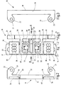
- Fig. 1
- eine schematische Draufsicht einer Befestigungsvorrichtung für Elektromotoren, angebracht an einem Standfuß,
- Fig. 2
- eine schematische Seitenansicht lediglich der Befestigungsvorrichtung in Pfeilrichtung II in Fig. 1,
- Fig. 3
- eine schematische Seitenansicht der Befestigungsvorrichtung in Pfeilrichtung III in Fig. 1,
- Fig. 4
- eine schematische teilweise geschnittene Seitenansicht der Befestigungsvorrichtung mit Standfuß in Pfeilrichtung IV in Fig. 1, wobei die Befestigungsvorrichtung an einem zu befestigenden Elektromotor angebracht ist,
- Fig. 5
- eine schematische Ansicht der Unterseite der Befestigungsvorrichtung in Fig. 1 ohne Standfuß.
Claims (20)
- Befestigungsvorrichtung (10) für Elektromotoren (11), insbesondere für Spaltpolmotoren, nach Art einer Konsole zur Befestigung an einer Halterung (14), z. B. an einem Standfuß (15),
gekennzeichnet durch
einen Tragschenkel (19) und einen davon etwa rechtwinklig abstrebenden Befestigungsschenkel (24), der mehrere Durchgangsöffnungen (25) für den Durchgriff von am Befestigungsschenkel (24) angreifenden Befestigungsmitteln (26), insbesondere Befestigungsschrauben, aufweist, wobei die sowohl in Querrichtung als auch in Längsrichtung des Befestigungsschenkels (24) vorgesehenen Durchgangsöffnungen (25) in solchen Abständen aufeinander folgen, dass zwei Befestigungsmittel (26) mit unterschiedlichem in Querrichtung und/oder Längsrichtung des Befestigungsschenkels (24) gemessenem Abstand voneinander hindurchpassen. - Befestigungsvorrichtung nach Anspruch 1,
dadurch gekennzeichnet, dass der Befestigungsschenkel (24) vier quer dazu gerichtete Reihen (27 bis 30) von Durchgangsöffnungen (25) aufweist, von denen zwei Reihen (27, 29) in Längsrichtung des Befestigungsschenkels (24) einen geringeren Abstand voneinander aufweisen als die beiden anderen Reihen (28, 30). - Befestigungsvorrichtung nach Anspruch 2,
dadurch gekennzeichnet, dass jede der vier Reihen (27 bis 30) drei Durchgangsöffnungen (25) oder mehr aufweist. - Befestigungsvorrichtung nach Anspruch 3,
dadurch gekennzeichnet, dass die beiden mit in Längsrichtung des Befestigungsschenkels (24) gesehen kleinerem Abstand voneinander verlaufenden Reihen (27,29) von Durchgangsöffnungen (25) einen Abstand von 18 mm, gemessen von Mitte Durchgangsöffnung (25) zu Mitte Durchgangsöffnung (25), aufweisen. - Befestigungsvorrichtung nach Anspruch 3 oder 4,
dadurch gekennzeichnet, dass die beiden mit in Längsrichtung des Befestigungsschenkels (24) gesehen größerem Abstand voneinander verlaufenden Reihen (29,30) von Durchgangsöffnungen (25) einen Abstand von 26 mm, gemessen von Mitte Durchgangsöffnung (25) zu Mitte Durchgangsöffnung (15), aufweisen. - Befestigungsvorrichtung nach einem der Ansprüche 1 bis 5,
dadurch gekennzeichnet, dass der Befestigungsschenkel (24) zumindest ein Langloch (31) enthält, das sich in Querrichtung des Befestigungsschenkels (24) erstreckt. - Befestigungsvorrichtung nach Anspruch 6,
dadurch gekennzeichnet, dass das Langloch (31) mittig zwischen den beidseitig davon mit Abstand verlaufenden Reihen (27,28 und 29,30) von Durchgangsöffnungen (25) angeordnet ist. - Befestigungsvorrichtung nach Anspruch 6 oder 7,
dadurch gekennzeichnet, dass das Langloch (31) eine Länge von mindestens 22 mm aufweist. - Befestigungsvorrichtung nach einem der Ansprüche 1 bis 8,
dadurch gekennzeichnet, dass der Bereich des Befestigungsschenkels (24), der die Durchgangsöffnungen (25) und/oder das mindestens eine Langloch (31) aufweist, als etwa kastenförmiger Mittelteil (32) ausgebildet ist, derart, dass durch die Durchgangsöffnungen (25) bzw. das mindestens eine Langloch (31) hindurchgreifende Befestigungsmittel (26), insbesondere Befestigungsschrauben, mit ihren Köpfen (33) im Kasteninneren aufnehmbar sind. - Befestigungsvorrichtung nach einem der Ansprüche 1 bis 9,
dadurch gekennzeichnet, dass der Befestigungsschenkel (24) sich an beiden Enden in Längsrichtung jeweils anschließende Flachteile (34) aufweist, die jeweils ebenfalls mit Durchgangsöffnungen (35) versehen sind. - Befestigungsvorrichtung nach Anspruch 10,
dadurch gekennzeichnet, dass jeder Flachteil (34) zwei quer zum Befestigungsschenkel (24) gerichtete Reihen (36, 37 bzw. 38, 39) von Durchgangsöffnungen (35) aufweist, wobei die Durchgangsöffnungen (35) in Längsrichtung und in Querrichtung in Abständen aufeinanderfolgen. - Befestigungsvorrichtung nach Anspruch 10 oder 11,
dadurch gekennzeichnet, dass die Flachteile (34) mit dem Mittelteil (32) des Befestigungsschenkels (24) über zerbrechbare Dünnstege (40) verbunden sind. - Befestigungsvorrichtung nach einem der Ansprüche 10 bis 12,
dadurch gekennzeichnet, dass die Flachteile (34) eine geringere Dicke als der Mittelteil (32) des Befestigungsschenkels (24) aufweisen, wobei für die Dicke ein Maß eines Unterlegteiles vorgegeben ist und ein abgebrochener Flachteil ein Unterlegteil bildet. - Befestigungsvorrichtung nach Anspruch 13,
dadurch gekennzeichnet, dass die Flachteile (34) eine Querschnittsdicke von 3 mm aufweisen. - Befestigungsvorrichtung nach einem der Ansprüche 1 bis 14,
dadurch gekennzeich net,
dass bei den Durchgangsöffnungen (25,35) des Befestigungsschenkels (24) und/oder jedes Flachteils (34) die Durchgangsöffnungen einer Reihe gegenüber denjenigen der benachbarten Reihe einen Versatz, betrachtet in Richtung der Reihe, aufweisen, der z.B. 2,5 mm beträgt. - Befestigungsvorrichtung nach einem der Ansprüche 1 bis 15,
dadurch gekennzeichnet, dass der Tragschenkel (19) als Streifenteil (20) ausgebildet ist, der sich in Längsrichtung des Befestigungsschenkels (24) an einer Seite dieses erstreckt. - Befestigungsvorrichtung nach Anspruch 16
dadurch gekennzeichnet, dass der Streifenteil (20) mit dem etwa kastenförmigen Mittelteil (32) des Befestigungsschenkels (24) einstückig verbunden ist. - Befestigungsvorrichtung nach Anspruch 16 oder 17,
dadurch gekennzeichnet, dass der Streifenteil (20) an beiden Enden hochragende Befestigungsaugen (21) aufweist, die Durchlässe (22) zur Befestigung am Elektromotor (11), z. B. an dessen Lagerendschild (13), enthalten. - Befestigungsvorrichtung nach einem der Ansprüche 1 bis 18,
dadurch gekennzeichnet, dass der Tragschenkel (19) und der Befestigungsschenkel (24) ein einstückiges Formteil, insbesondere aus Kunststoff, bilden. - Befestigungsvorrichtung nach einem der Ansprüche 1 bis 17,
dadurch gekennzeichnet, dass der Streifenteil (20) mitsamt dem mit seinem etwa kastenförmigen Mittelteil (32) damit verbundenen Befestigungsschenkel (24) oder lediglich der Befestigungsschenkel (24) einstückiger Teil des Elektromotors (11), z. B. des Lagerendschildes (13) dieses, ist, insbesondere daran angegossen ist.
Applications Claiming Priority (2)
| Application Number | Priority Date | Filing Date | Title |
|---|---|---|---|
| DE10051060 | 2000-10-14 | ||
| DE10051060A DE10051060A1 (de) | 2000-10-14 | 2000-10-14 | Befestigungsvorrichtung für Elektromotoren, insbesondere für Spaltpolmotoren |
Publications (3)
| Publication Number | Publication Date |
|---|---|
| EP1204192A2 true EP1204192A2 (de) | 2002-05-08 |
| EP1204192A3 EP1204192A3 (de) | 2004-01-02 |
| EP1204192B1 EP1204192B1 (de) | 2008-05-21 |
Family
ID=7659852
Family Applications (1)
| Application Number | Title | Priority Date | Filing Date |
|---|---|---|---|
| EP01114081A Expired - Lifetime EP1204192B1 (de) | 2000-10-14 | 2001-06-09 | Befestigungsvorrichtung für Elektromotoren, insbesondere Spaltpolmotoren |
Country Status (4)
| Country | Link |
|---|---|
| EP (1) | EP1204192B1 (de) |
| AT (1) | ATE396532T1 (de) |
| DE (3) | DE10051060A1 (de) |
| HK (1) | HK1048021A1 (de) |
Family Cites Families (6)
| Publication number | Priority date | Publication date | Assignee | Title |
|---|---|---|---|---|
| US1822342A (en) * | 1928-06-04 | 1931-09-08 | Electric Auto Lite Co | Frame structure for dynamo-electric machines |
| US3983429A (en) * | 1975-05-08 | 1976-09-28 | Westinghouse Electric Corporation | Adjustable motor base |
| US4033531A (en) * | 1976-04-27 | 1977-07-05 | Fred Levine | Mounting assembly with selectively used one-piece or two-piece brackets |
| US4859889A (en) * | 1988-06-28 | 1989-08-22 | General Electric Company | Dynamoelectric machine |
| JP3002747B2 (ja) * | 1990-01-09 | 2000-01-24 | 芝浦メカトロニクス株式会社 | モールドモータ |
| CA2087763C (en) * | 1992-02-11 | 2002-07-02 | Jimmy Cochimin | Stator frame for dynamoelectric machine and method for making same |
-
2000
- 2000-10-14 DE DE10051060A patent/DE10051060A1/de not_active Withdrawn
- 2000-10-25 DE DE20018678U patent/DE20018678U1/de not_active Expired - Lifetime
-
2001
- 2001-06-09 DE DE50113986T patent/DE50113986D1/de not_active Expired - Fee Related
- 2001-06-09 EP EP01114081A patent/EP1204192B1/de not_active Expired - Lifetime
- 2001-06-09 AT AT01114081T patent/ATE396532T1/de not_active IP Right Cessation
-
2002
- 2002-11-08 HK HK02108139.3A patent/HK1048021A1/zh unknown
Also Published As
| Publication number | Publication date |
|---|---|
| DE50113986D1 (de) | 2008-07-03 |
| EP1204192A3 (de) | 2004-01-02 |
| ATE396532T1 (de) | 2008-06-15 |
| DE20018678U1 (de) | 2001-01-25 |
| EP1204192B1 (de) | 2008-05-21 |
| DE10051060A1 (de) | 2002-04-18 |
| HK1048021A1 (zh) | 2003-03-14 |
Similar Documents
| Publication | Publication Date | Title |
|---|---|---|
| EP1921722B1 (de) | Schaltschrank für eine elektrische Installationsverteilung | |
| DE10156931C2 (de) | Universal-Einbausatz für ein in ein Rahmengestell einbaubares Einbaugerät | |
| DE29716229U1 (de) | Vorrichtung zur Befestigung und Verdrahtung einer Vielzahl von elektrischen Einheiten, insbesondere in einem Schaltschrank | |
| DE102016107565A1 (de) | Anordnung für die berührungssichere Kontaktierung eines Stromsammelschienensystems | |
| EP0168672A2 (de) | Gerätetür eines Haushalt-Einbaugerätes mit Türblatt | |
| DE4013989A1 (de) | Traegervorrichtung fuer einbauten in regalen | |
| EP0776077B1 (de) | Vorrichtung zum Befestigen von Zusatzeinrichtungen an Hutschienen | |
| EP1204192A2 (de) | Befestigungsvorrichtung für Elektromotoren, insbesondere Spaltpolmotoren | |
| EP0623530A1 (de) | Hängefördereinrichtung mit einem Montageprofilsatz | |
| DE2644397C3 (de) | Möbelaufbausystem | |
| WO1997031557A1 (de) | Aufnahmerahmen für einbaugeräte von bedien- und arbeitspulten | |
| DE3209550C2 (de) | Gehäuse für elektrotechnische Geräte | |
| DE4244143C2 (de) | Rahmengestell aus Rahmenschenkeln für einen Schaltschrank | |
| DE29610693U1 (de) | Baugruppenträger mit zentrierbaren Frontplatten aufweisenden, einsteckbaren Baugruppen | |
| DE2347284A1 (de) | Montageplatte zur befestigung von bauteilen elektrischer schaltungen fuer die verwendung in elektrischen schaltschraenken und dergleichen | |
| DE69206475T2 (de) | Bodenrahmen für elektrischen Kasten. | |
| EP0455973A1 (de) | Führungsleiste für Aufzugstür | |
| DE10315503B3 (de) | Installationsgerät für Sammelschienen | |
| DE1625345C3 (de) | Befestigungseinrichtung | |
| DE10147342C2 (de) | Schaltschrank | |
| CH721511A2 (de) | Befestigungselement, Verfahren zur Herstellung einer Wand sowie zugehöriges Set | |
| DE29605230U1 (de) | Montagevorrichtung für einen Schaltschrank | |
| DE7502291U (de) | Perforierte Platine | |
| DE1515826A1 (de) | Anreihbarer Aufputzverteiler | |
| DE2344808A1 (de) | Verdrahtungsrahmen fuer eine schalttafel |
Legal Events
| Date | Code | Title | Description |
|---|---|---|---|
| PUAI | Public reference made under article 153(3) epc to a published international application that has entered the european phase |
Free format text: ORIGINAL CODE: 0009012 |
|
| AK | Designated contracting states |
Kind code of ref document: A2 Designated state(s): AT BE CH CY DE DK ES FI FR GB GR IE IT LI LU MC NL PT SE TR |
|
| AX | Request for extension of the european patent |
Free format text: AL;LT;LV;MK;RO;SI |
|
| PUAL | Search report despatched |
Free format text: ORIGINAL CODE: 0009013 |
|
| AK | Designated contracting states |
Kind code of ref document: A3 Designated state(s): AT BE CH CY DE DK ES FI FR GB GR IE IT LI LU MC NL PT SE TR |
|
| AX | Request for extension of the european patent |
Extension state: AL LT LV MK RO SI |
|
| 17P | Request for examination filed |
Effective date: 20040504 |
|
| 17Q | First examination report despatched |
Effective date: 20040709 |
|
| AKX | Designation fees paid |
Designated state(s): AT BE CH CY DE DK ES FI FR GB GR IE IT LI LU MC NL PT SE TR |
|
| GRAP | Despatch of communication of intention to grant a patent |
Free format text: ORIGINAL CODE: EPIDOSNIGR1 |
|
| GRAS | Grant fee paid |
Free format text: ORIGINAL CODE: EPIDOSNIGR3 |
|
| GRAA | (expected) grant |
Free format text: ORIGINAL CODE: 0009210 |
|
| AK | Designated contracting states |
Kind code of ref document: B1 Designated state(s): AT BE CH CY DE DK ES FI FR GB GR IE IT LI LU MC NL PT SE TR |
|
| REG | Reference to a national code |
Ref country code: GB Ref legal event code: FG4D Free format text: NOT ENGLISH |
|
| REG | Reference to a national code |
Ref country code: CH Ref legal event code: EP |
|
| REF | Corresponds to: |
Ref document number: 50113986 Country of ref document: DE Date of ref document: 20080703 Kind code of ref document: P |
|
| REG | Reference to a national code |
Ref country code: IE Ref legal event code: FG4D Free format text: LANGUAGE OF EP DOCUMENT: GERMAN |
|
| PG25 | Lapsed in a contracting state [announced via postgrant information from national office to epo] |
Ref country code: ES Free format text: LAPSE BECAUSE OF FAILURE TO SUBMIT A TRANSLATION OF THE DESCRIPTION OR TO PAY THE FEE WITHIN THE PRESCRIBED TIME-LIMIT Effective date: 20080901 Ref country code: FI Free format text: LAPSE BECAUSE OF FAILURE TO SUBMIT A TRANSLATION OF THE DESCRIPTION OR TO PAY THE FEE WITHIN THE PRESCRIBED TIME-LIMIT Effective date: 20080521 |
|
| NLV1 | Nl: lapsed or annulled due to failure to fulfill the requirements of art. 29p and 29m of the patents act | ||
| PG25 | Lapsed in a contracting state [announced via postgrant information from national office to epo] |
Ref country code: NL Free format text: LAPSE BECAUSE OF FAILURE TO SUBMIT A TRANSLATION OF THE DESCRIPTION OR TO PAY THE FEE WITHIN THE PRESCRIBED TIME-LIMIT Effective date: 20080521 |
|
| BERE | Be: lapsed |
Owner name: GLEMS-TECHNIK G.M.B.H. Effective date: 20080630 |
|
| REG | Reference to a national code |
Ref country code: IE Ref legal event code: FD4D |
|
| REG | Reference to a national code |
Ref country code: HK Ref legal event code: WD Ref document number: 1048021 Country of ref document: HK |
|
| PG25 | Lapsed in a contracting state [announced via postgrant information from national office to epo] |
Ref country code: IE Free format text: LAPSE BECAUSE OF FAILURE TO SUBMIT A TRANSLATION OF THE DESCRIPTION OR TO PAY THE FEE WITHIN THE PRESCRIBED TIME-LIMIT Effective date: 20080521 Ref country code: MC Free format text: LAPSE BECAUSE OF NON-PAYMENT OF DUE FEES Effective date: 20080630 Ref country code: DK Free format text: LAPSE BECAUSE OF FAILURE TO SUBMIT A TRANSLATION OF THE DESCRIPTION OR TO PAY THE FEE WITHIN THE PRESCRIBED TIME-LIMIT Effective date: 20080521 Ref country code: SE Free format text: LAPSE BECAUSE OF FAILURE TO SUBMIT A TRANSLATION OF THE DESCRIPTION OR TO PAY THE FEE WITHIN THE PRESCRIBED TIME-LIMIT Effective date: 20080821 Ref country code: PT Free format text: LAPSE BECAUSE OF FAILURE TO SUBMIT A TRANSLATION OF THE DESCRIPTION OR TO PAY THE FEE WITHIN THE PRESCRIBED TIME-LIMIT Effective date: 20081021 |
|
| REG | Reference to a national code |
Ref country code: CH Ref legal event code: PL |
|
| PLBE | No opposition filed within time limit |
Free format text: ORIGINAL CODE: 0009261 |
|
| STAA | Information on the status of an ep patent application or granted ep patent |
Free format text: STATUS: NO OPPOSITION FILED WITHIN TIME LIMIT |
|
| PG25 | Lapsed in a contracting state [announced via postgrant information from national office to epo] |
Ref country code: BE Free format text: LAPSE BECAUSE OF NON-PAYMENT OF DUE FEES Effective date: 20080630 |
|
| 26N | No opposition filed |
Effective date: 20090224 |
|
| PG25 | Lapsed in a contracting state [announced via postgrant information from national office to epo] |
Ref country code: CH Free format text: LAPSE BECAUSE OF NON-PAYMENT OF DUE FEES Effective date: 20080630 Ref country code: LI Free format text: LAPSE BECAUSE OF NON-PAYMENT OF DUE FEES Effective date: 20080630 |
|
| PG25 | Lapsed in a contracting state [announced via postgrant information from national office to epo] |
Ref country code: AT Free format text: LAPSE BECAUSE OF NON-PAYMENT OF DUE FEES Effective date: 20080609 |
|
| PGFP | Annual fee paid to national office [announced via postgrant information from national office to epo] |
Ref country code: FR Payment date: 20090618 Year of fee payment: 9 |
|
| PGFP | Annual fee paid to national office [announced via postgrant information from national office to epo] |
Ref country code: DE Payment date: 20090822 Year of fee payment: 9 Ref country code: GB Payment date: 20090623 Year of fee payment: 9 |
|
| PGFP | Annual fee paid to national office [announced via postgrant information from national office to epo] |
Ref country code: IT Payment date: 20090627 Year of fee payment: 9 |
|
| PG25 | Lapsed in a contracting state [announced via postgrant information from national office to epo] |
Ref country code: LU Free format text: LAPSE BECAUSE OF NON-PAYMENT OF DUE FEES Effective date: 20080609 Ref country code: CY Free format text: LAPSE BECAUSE OF FAILURE TO SUBMIT A TRANSLATION OF THE DESCRIPTION OR TO PAY THE FEE WITHIN THE PRESCRIBED TIME-LIMIT Effective date: 20080521 |
|
| PG25 | Lapsed in a contracting state [announced via postgrant information from national office to epo] |
Ref country code: TR Free format text: LAPSE BECAUSE OF FAILURE TO SUBMIT A TRANSLATION OF THE DESCRIPTION OR TO PAY THE FEE WITHIN THE PRESCRIBED TIME-LIMIT Effective date: 20080521 |
|
| PG25 | Lapsed in a contracting state [announced via postgrant information from national office to epo] |
Ref country code: GR Free format text: LAPSE BECAUSE OF FAILURE TO SUBMIT A TRANSLATION OF THE DESCRIPTION OR TO PAY THE FEE WITHIN THE PRESCRIBED TIME-LIMIT Effective date: 20080822 |
|
| GBPC | Gb: european patent ceased through non-payment of renewal fee |
Effective date: 20100609 |
|
| REG | Reference to a national code |
Ref country code: FR Ref legal event code: ST Effective date: 20110228 |
|
| PG25 | Lapsed in a contracting state [announced via postgrant information from national office to epo] |
Ref country code: IT Free format text: LAPSE BECAUSE OF NON-PAYMENT OF DUE FEES Effective date: 20100609 |
|
| PG25 | Lapsed in a contracting state [announced via postgrant information from national office to epo] |
Ref country code: DE Free format text: LAPSE BECAUSE OF NON-PAYMENT OF DUE FEES Effective date: 20110101 |
|
| PG25 | Lapsed in a contracting state [announced via postgrant information from national office to epo] |
Ref country code: FR Free format text: LAPSE BECAUSE OF NON-PAYMENT OF DUE FEES Effective date: 20100630 |
|
| PG25 | Lapsed in a contracting state [announced via postgrant information from national office to epo] |
Ref country code: GB Free format text: LAPSE BECAUSE OF NON-PAYMENT OF DUE FEES Effective date: 20100609 |