EP1204337B1 - AUSGABEVORRICHTUNG FüR KUNSTSTOFF-BEFESTIGUNGSELEMENTE - Google Patents
AUSGABEVORRICHTUNG FüR KUNSTSTOFF-BEFESTIGUNGSELEMENTE Download PDFInfo
- Publication number
- EP1204337B1 EP1204337B1 EP00916055A EP00916055A EP1204337B1 EP 1204337 B1 EP1204337 B1 EP 1204337B1 EP 00916055 A EP00916055 A EP 00916055A EP 00916055 A EP00916055 A EP 00916055A EP 1204337 B1 EP1204337 B1 EP 1204337B1
- Authority
- EP
- European Patent Office
- Prior art keywords
- fastener
- casing
- needle
- dispensing tool
- ejector rod
- Prior art date
- Legal status (The legal status is an assumption and is not a legal conclusion. Google has not performed a legal analysis and makes no representation as to the accuracy of the status listed.)
- Expired - Lifetime
Links
- 239000004033 plastic Substances 0.000 title abstract description 24
- 229920003023 plastic Polymers 0.000 title abstract description 24
- 230000007246 mechanism Effects 0.000 claims description 18
- 238000010168 coupling process Methods 0.000 claims description 14
- 238000005859 coupling reaction Methods 0.000 claims description 14
- 230000008878 coupling Effects 0.000 claims description 13
- 238000012544 monitoring process Methods 0.000 claims 1
- 238000000034 method Methods 0.000 abstract description 8
- 239000000463 material Substances 0.000 description 15
- 239000002991 molded plastic Substances 0.000 description 11
- 239000002184 metal Substances 0.000 description 9
- 230000006378 damage Effects 0.000 description 5
- 229920002635 polyurethane Polymers 0.000 description 5
- 239000004814 polyurethane Substances 0.000 description 5
- 238000000465 moulding Methods 0.000 description 4
- 239000004677 Nylon Substances 0.000 description 3
- 208000027418 Wounds and injury Diseases 0.000 description 3
- 208000014674 injury Diseases 0.000 description 3
- 238000003780 insertion Methods 0.000 description 3
- 230000037431 insertion Effects 0.000 description 3
- 229920001778 nylon Polymers 0.000 description 3
- 230000008901 benefit Effects 0.000 description 2
- 210000000988 bone and bone Anatomy 0.000 description 2
- 238000004806 packaging method and process Methods 0.000 description 2
- 230000008569 process Effects 0.000 description 2
- 206010069803 Injury associated with device Diseases 0.000 description 1
- 239000004743 Polypropylene Substances 0.000 description 1
- 230000009471 action Effects 0.000 description 1
- 230000001154 acute effect Effects 0.000 description 1
- 230000008859 change Effects 0.000 description 1
- 230000007423 decrease Effects 0.000 description 1
- 230000009977 dual effect Effects 0.000 description 1
- 229920001971 elastomer Polymers 0.000 description 1
- 239000004744 fabric Substances 0.000 description 1
- 238000012840 feeding operation Methods 0.000 description 1
- 238000001746 injection moulding Methods 0.000 description 1
- 239000000203 mixture Substances 0.000 description 1
- 230000004048 modification Effects 0.000 description 1
- 238000012986 modification Methods 0.000 description 1
- 239000000123 paper Substances 0.000 description 1
- -1 polypropylene Polymers 0.000 description 1
- 229920001155 polypropylene Polymers 0.000 description 1
- 238000010008 shearing Methods 0.000 description 1
- 229910001220 stainless steel Inorganic materials 0.000 description 1
- 239000010935 stainless steel Substances 0.000 description 1
- 239000002699 waste material Substances 0.000 description 1
Images








Classifications
-
- B—PERFORMING OPERATIONS; TRANSPORTING
- B65—CONVEYING; PACKING; STORING; HANDLING THIN OR FILAMENTARY MATERIAL
- B65C—LABELLING OR TAGGING MACHINES, APPARATUS, OR PROCESSES
- B65C7/00—Affixing tags
- B65C7/003—Affixing tags using paddle-shaped plastic pins
- B65C7/005—Portable tools
-
- G—PHYSICS
- G09—EDUCATION; CRYPTOGRAPHY; DISPLAY; ADVERTISING; SEALS
- G09F—DISPLAYING; ADVERTISING; SIGNS; LABELS OR NAME-PLATES; SEALS
- G09F3/00—Labels, tag tickets, or similar identification or indication means; Seals; Postage or like stamps
- G09F3/08—Fastening or securing by means not forming part of the material of the label itself
- G09F3/14—Fastening or securing by means not forming part of the material of the label itself by strings, straps, chains, or wires
Definitions
- the present invention relates generally to the fastening of objects using plastic fasteners and relates more particularly to a novel fastener dispensing tool.
- Certain articles of clothing are often packaged and sold in a folded condition so as to minimize any wrinkling of the article and so as to present the article in an otherwise flattering manner.
- the article is maintained in a folded condition by means of one or more straight metal pins, each of said straight metal pins typically comprising an elongated shaft terminating at one end in a sharp tip designed to penetrate the article and at the other end in a rounded head designed not to penetrate the article.
- the article is folded, and a plurality of said pins are used to maintain the article in its folded condition by securing the article to itself at a plurality of different locations.
- one or more of said pins are additionally used to secure the shirt to a piece of cardboard or to a similar backing material.
- the act of using straight metal pins to maintain an article of clothing in a folded condition is typically referred to in the art as "shirt-pinning.”
- Still another shortcoming associated with the use of straight metal pins is that such pins, when inserted, may cause damage to the article, either by snagging and tearing the article or by creating a conspicuous insertion hole in the article. Still yet another shortcoming associated with the use of straight metal pins is that such pins, once inserted into an article of clothing, can be difficult to access and manipulate in such a way as to enable their removal.
- Plastic fasteners of the type comprising an elongated flexible filament having a first enlargement at one end thereof and a second enlargement at the opposite end thereof are well-knoinrn and have been widely used in the attachment of merchandise tags to articles of commerce, in the coupling or re-coupling of buttons to garments, in the binding of a shoe upper during the process of shoe-lasting, and in various packaging applications.
- plastic fastener see , for example, Fig.1 of U.S. Patent No.
- the first enlargement has the shape of a first transverse bar and the second enlargement has the shape of a paddle or the shape of a second transverse bar, the first transverse bar and the paddle (or second transverse bar) extending in planes parallel to one another.
- the first enlargement has the shape of a transverse bar and the second enlargement has the shape of a knob or pin head.
- the first enlargement has the shape of a transverse bar or the shape of a plug and the second enlargement has the shape of a socket, said socket being adapted to receive said transverse bar or said plug.
- Plastic fasteners of the various types described above are typically molded as parts of a unitary fastener clip.
- An example of such a fastener clip is disclosed in U.S. Patent No. 3,733,657).
- the clip of the aforementioned '657 patent includes a plurality of fasteners, each of said fasteners comprising a flexible filament having a first transverse bar (or "cross-bar") at one end thereof and a paddle or a second transverse bar (or "cross-bar”) at the opposite end thereof, the transverse bar and the paddle (or second transverse bar) of each fastener extending in planes parallel to one another.
- the fasteners are arranged relative to one another so that the respective transverse bars are spaced apart and oriented side-by-side and parallel to one another and so that the respective paddles (or second transverse bars) are spaced apart and oriented side-by-side and parallel to one another.
- the clip of the foregoing '657 patent also includes a runner bar, said runner bar extending perpendicularly relative to the respective transverse bars and being connected to each of the transverse bars by a severable connector.
- the clip of said '657 patent further includes a severable member interconnecting each pair of adjacent.paddles (or second transverse bars).
- DENNISON ® SWIFTACH ® fastener clips comprising fasteners of the type having a cross-bar at one end of a flexible filament and a paddle at the opposite end of the flexible filament are generally made of polypropylene or nylon and are typically used to attach merchandise tags and the like to articles of clothing.
- the filaments of such fasteners are typically at least about 12.5 mm in length.
- DENNISON ® SWIFTACH ® fastener clips comprising fasteners of the type having a first cross-bar at one end of a flexible filament and a second cross-bar at the opposite end of the flexible filament are made of nylon and are used to attach merchandise tags and the like to a wide variety of articles of commerce.
- fasteners are used in shoe-tasting applications and in packaging applications, where the high tensile strength afforded by the use of nylon in the fastener is desirable.
- the filaments of such fasteners are typically at least about 6.35 mm in length.
- the above-described fastener clip exemplified by the family of DENNISON ® SWIFTACH ® fastener clips, has not been used to maintain an article of clothing, such as a dress shirt, in a folded condition.
- fastener stock A second type of fastener clip (or "fastener stock”) is disclosed in U.S. Patent No. 4,039,078, inventor Bone, issued August 2, 1977.
- the fastener stock comprises two undivided elongated and continuous plastic side members having a plurality of plastic cross links coupled to and between each of said side members, each of the links being preferably spaced equidistantly apart from each other.
- the fastener stock is designed to be separated or divided, e.g., by cutting, severing, rupturing or shearing the side members, to provide a plurality of fasteners, each of said fasteners preferably having a substantially H shape.
- PLASTIC STAPLE TM fasteners are typically made of polyurethane and are often used to attach tags, at two distinct points, to pants and similar clothing articles. It is the understanding of the present inventors that, for a limited time in the past, a third party used PLASTIC STAPLE TM fasteners to "pin" shirts, albeit not dress shirts or other shirts of a fine material, so as to maintain the shirts in a folded condition.
- PLASTIC STAPLE TM fasteners did not have sufficient tensile strength to maintain the shirt in its folded condition (PLASTIC STAPLE TM fasteners typically having a tensile strength of about 594.308-635.026g (1.2-1.4 pounds)).
- Tools for dispensing individual fasteners from multi-fastener clips of the two different types described above are known, examples of such tools including the Dennison ® Mark II TM SWIFTACH ® tool, as well as those tools disclosed in U.S. Patent Nos. 5,772,073, 5,683,025, 5,024,365, 4,533,076,4,456,161,4,121,487, and 4,456,123.
- the US 3,103,666 discloses a bar-lock tag for fasten a tag to a fabric, and an apparatus for applying such attachments.
- the apparatus includes a hollow needle elongately slotted along one side, and a plunger for driving the bar of an attachment through the needle with its filament projecting through the slot.
- a system for attaching price tags to garments and for other joining applications using plastic fasteners dispensed through hollow, slotted needles is disclosed in the US 4,456,123.
- the system comprises a new method and tool for dispensing fasteners supplied in long lengths, together with improved fastener stock adapted for use therewith and for molding in continuous lengths.
- a cluster type tag pin assembly having a multiplicity of tag pins adapted for use in securing price tags or the like to sold goods is disclosed in the US 4,417,656.
- the tag pin assembly includes a large number of tag pins each having a head portion, a cross bar and a filament portion through which the cross bar is connected to the head portion.
- Each side surface of the cross bar of each tag pin is formed at the central portion thereof with an expanded portion, and expanded portions of each adjacent cross bars are mutually joined.
- a fastener assembly comprising a number of fasteners each comprising a head, a crossbar and a filament interconnecting the head and the crossbar, each adjacent crossbars being interconnected through a connecting element in a manner of not undergoing a change in their relative positions, the number of crossbars in the fastener assembly being arranged in the form of a sheet as a whole.
- a system is described in the US 4,456,161 for attaching price tags to garments and for other joining applications using plastic fasteners dispensed through hollow, slotted needles.
- the system comprises a new method and tool for dispensing fasteners supplied in long lengths, together with improved fastener stock adapted for the use therewith and for molding in continuous lengths.
- a plastic fastener for clothing and a method for its use is described by C. Deschenes, W. Cooper and C. Grendol in the WO 00/14702.
- a tag dispensing and attaching apparatus is disclosed by D. Duchin in the US-patent 4,610,384.
- a pistol-shaped tag fastening device having a grip, in which a trigger lever is pivotally mounted on a pin mounted on the inside of the grip is disclosed in the US-patent 5,501,002.
- a loop pin attaching device for tag hanging is described in the US 5,738,265, with a drive lever which is selectively moveable between a first, unactivated and a second, activated position.
- the US 4,536,933 discloses a method of connecting ends of a fastener of the type having a filament portion of a predetermined length, a tubular socket portion connected to one end of the filament portion and a pin portion connected to the other end of the filament portion, as well as a device suitable for carrying out this method.
- buttons attaching device for attaching a button to a layer of material is described in the US 5,788,138.
- a fastener dispensing tool comprising (a) a casing, said casing being shaped to receive, entirely within said casing, a clip of fasteners, each of said fasteners in said clip comprising a flexible filament having a first enlarged portion at a first end thereof and a second enlarged portion at a second end thereof; (b) a hollow, slotted needle coupled to said casing, said hollow, slotted needle being adapted to receive the first enlarged portion of a fastener; (c) wherein said feed track terminates behind said hollow, slotted needle in a direction substantially perpendicular to the longitudinal axis of said hollow, slotted needle; and (d) an ejector rod disposed within said casing and insertable into said hollow, slotted needle for ejecting from said hollow, slotted needle an enlarged portion of a fastener disposed therein.
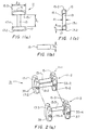
- FIGs. 1(a) through 1(c) there are shown side top and front views, respectively, of one embodiment of a plastic fastener well-suited for maintaining a dress shirt in a folded condition, said plastic fastener being constructed according to the teachings of the present invention and being represented generally by reference numeral 11.
- fastener 11 is particularly well-suited for maintaining a dress shirt or the like in a folded condition, it is not limited in its utility thereto and may be used in a variety of different applications including, but not limited to fixing together pairs of socks, coupling together sheets of paper, fixing dress shirts to cardboard supports fixing doll clothing to cardboard supports, etc.
- Fastener 11 which is a unitary structure preferably made by molding, comprises a flexible filament 13.
- filament 13 When molded, filament 13 has a length l 1 of about 1.65 mm and a diameter d 1 of about 0.4 mm; filament 13 is thereafter stretched in the conventional manner to a length of approximately 4.3 mm and a diameter of approximately 0.2 mm.
- filament 13 has a generally cylindrical shape, filament 13 need not be cylindrically shaped and may take a variety of shapes, including those specified in commonly-assigned co-pending U.S. Patent Application Serial No. 09/416,784.
- Fastener 11 also comprises a first cross-bar 15 and a second cross-bar 17, cross-bar 15 being disposed at a first end of filament 13, cross-bar 17 being disposed at a second end of filament 13, cross-bars 15 and 17 being parallel to one another.
- Each of cross-bars 15 and 17 has a length l 2 of approximately 1.78 mm, a width w 1 of approximately 0.55 mm and a height h 1 of approximately 0.55 mm.
- cross-bars 15 and 17 are shaped so as to have flat inner surfaces 15-1 and 17-1, respectively, proximate to filament 13 and convex outer surfaces 15-2 and 17-2, respectively, distal to filament 13, cross-bars 15 and 17 need not be so shaped.
- cross-bars 15 and 17 may take a variety of forms, including those of the enlarged ends described in U.S. Patent Application Serial No. 09/416,784.
- Fastener 11 is preferably made of a polyurethane that gives filament 13 a tensile strength of about 2 pounds.
- said polyurethane is not the only type of material of which fastener 11 may be made and that other plastic materials (or combinations of materials) capable of providing filament 13 with a tensile strength in the range of about 907.18-1814.36g (2-4 pounds) (or whatever tensile strength is desirable based upon the particular use to which fastener 11 is put) are also suitable for purposes of the present invention.
- filament 13 is made of a polyurethane, it has a certain degree of elasticity - a property which may be desirable in certain applications.
- FIGs. 2(a) and 2(b) there are shown partially-expioded perspective and partially-exploded side views, respectively, of one embodiment of a fastener clip constructed according to the teachings of the present invention, the fastener clip being represented generally by reference numeral 31.
- Clip 31 which is a unitary structure preferably made by molding, comprises a plurality of fasteners 11-1 through 11-3, fasteners 11 being arranged in a parallel, side-by-side, spaced orientation. Although only three fasteners 11 are shown in clip 31, it is to be understood that the number of fasteners 11 in clip 31 is illustrative only (In fact, in a preferred embodiment, clip 31 comprises one hundred twenty-five fasteners 11.)
- Clip 31 also includes a first plurality of severable connector posts 33-1 and 33-2 and a second plurality of severable connector posts 35-1 and 35-2, connector posts 33 connecting the mutually-opposing sides of adjacent cross-bars 15 at their approximate midpoints and extending in a substantially perpendicular direction relative to the longitudinal axes of cross-bars 15, connector posts 35 connecting the mutually-opposing sides of adjacent cross-bars 17 at their approximate midpoints and extending in a substantially perpendicular direction relative to the longitudinal axes of cross-bars 17.
- FIGs. 3(a) through 3(c) are shown in Figs. 3(a) through 3(c), respectively.
- connector posts 33 and 35 have a length of approximately 0.25 mm.
- Connector posts 33 and 35 are strong enough to maintain the connection between adjacent fasteners 11 in clip 31 prior to the dispensing of individual fasteners 11 from clip 31 and, yet, are weak enough to be severed by the conventional severing action of a fastener dispensing tool.
- connector posts 33 and 35 have a certain degree of flexibility; consequently, because of the arrangement of posts 33 and 35 relative to cross-bars 15 and 17, respectively, adjacent fasteners 11 in clip 31 are permitted to pivot relative to one another, thereby enabling clip 31 to be bent into an arcuate shape.
- posts 33 and 35 preferably have a conical or tapered transverse cross-section that decreases in diameter from the fastener about to be dispensed (e.g., fastener 11-1) to the next fastener in the clip 31 (e.g., fastener 11-2) so that very little or nothing of the severed posts 33 and 35 that once connected the fastener about to be dispensed to the fastener previously attached to it remain on the about-to-be-dispensed fastener.
- the fastener about to be dispensed by the tool e.g., fastener 11-1 is able to sit substantially flush within a tool used to dispense the fastener.
- posts 33 and 35 need not be conical or tapered and, instead, may take a variety of shapes.
- Clip 31 further includes an extra pair of cross-bars 37 and 39, cross-bars 37 and 39 being identical to cross-bars 15 and 17, respectively, except for the fact that cross-bars 37 and 39 are not disposed at the ends of a flexible filament.
- Cross-bars 37 and 39 are arranged in a parallel, side-by-side, spaced orientation from cross-bars 15 and 17, respectively, of the last fastener 11 of clip 31 (in the present embodiment, fastener 11-3) and are severably connected thereto by connector posts 33-3 and 35-3, respectively.
- Connector post 33-3 is identical to connector posts 33-1 and 33-2
- connector post 35-3 is identical to connector posts 35-1 and 35-2.
- Cross-bars 37 and 39 serve to keep the last fastener of clip 31 properly oriented while it is being dispensed using the fastener dispensing tool described below.
- clip 31 does not include a runner bar. This may be advantageous since the runner bar of a fastener clip typically has no use once the fasteners originally attached thereto have been dispensed therefrom. As a result, the detached runner bar typically represents economically and environmentally undesirable waste material. In addition, severed connectors previously used to connect fasteners to a runner bar and still remaining on the runner bar after the fasteners have been detached therefrom often have an acute end which may undesirably snag on and damage merchandise when fasteners from the fastener clip are dispensed into such merchandise with a conventional fastener dispensing tool.
- Clip 31 may be made by injection molding, preferably using polyurethane or a similar material. According to a preferred embodiment, clip 31 is made by forming a fastener clip analogous to clip 31 but further comprising a runner bar severably connected to each of cross-bars 15 ( see , for example, fastener clip 11 of U.S.S.N. 09/464,022) and then by severing said runner bar from each of cross-bars 15 and removing the remnants of any connectors connecting said runner bar to cross-bars 15.
- runner bar-containing fastener clips could be substituted for runner bar-less clip 31 and used with an appropriately dimensioned version of a conventional fastener dispensing tool of the type adapted for use with runner bar-containing clips (an example of such a tool being an appropriately dimensioned Dennison ® Mark II TM SWIFTACH ® tool).
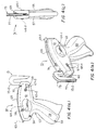
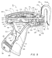
- FIGs. 4(a) through 4(c) and to Fig. 5 there are shown various views of a fastener dispensing tool that is particularly well-suited for use in dispensing individual fasteners from clip 31, said fastener dispensing tool being constructed according to the teachings of the present invention and being represented generally by reference numeral 51 (Fasteners dispensed by tool 51 may be used to maintain a dress shirt or the like in a folded condition or may be used in other fastening applications.)
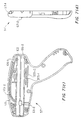
- Tool 51 includes a hollow, gun-shaped casing 53, casing 53 comprising a right half 55 (which is shown separately in Figs. 6(a) through 6(d)) and a left half 57 (which is shown separately in Figs. 7(a) through 7(d)).
- Halves 55 and 57 which may be fabricated from any convenient durable material, such as molded plastic, are joined together by a plurality of screws 58 and jointly define a handle portion 59 and a barrel portion 61.
- right half 55 and left half 57 also jointly define an opening 62 located at the front end of barrel portion 61, the purpose of opening 62 to be discussed below.
- an oval-shaped recess 63-1 is provided on the outer surface of the barrel portion of right half 55, and a corresponding oval-shaped recess 63-2 is provided on the outer surface of the barrel portion of left half 57.
- Recesses 63-1 and 63-2 are adapted to receive complementary-shaped inserts 64-1 and 64-2, respectively, inserts 64-1 and 64-2 being shown disposed in their respective recesses in Figs. 4(a) through 4(c).
- Inserts 64-1 and 64-2 may bear a logo or the like and/or may have a rubberized or gripping outer surface to prevent tool 51 from sliding across a table when placed thereon.
- a window 65-1 is provided in the barrel portion of right half 55, and a matching window 65-2 is provided in the barrel portion of left half 57.
- Windows 65-1 and 65-2 permit a user to monitor the status of a fastener clip 31 disposed inside casing 53.
- windows 65-1 and 65-2 provide an opening through which cross-bars 37 and 39 of a clip 31 may exit casing 53 once a clip 31 has been completely spent.
- An arrow 67-1 is formed on right half 55 towards the front of its barrel portion, and a matching arrow 67-2 is formed on left half 57 towards the front of its barrel portion. Arrows 67-1 and 67-2 are aligned with opening 62 and are designed to aid a user in aligning tool 51 with an object to be fastened, such as a dress-shirt.
- tool 51 further comprises a door 69 (shown separately in Figs. 8(a) through 8(d)).
- Door 69 which also may be made from molded plastic or the like, is pivotally mounted at its front end on a screw 70 secured to halves 55 and 57. When door 69 is closed, it substantially covers an opening formed between recesses 55-1 and 57-1 located along the top edges of halves 55 and 57, respectively (recesses 55-1 and 57-1 seen best in Figs. 6(d) and 7(d), respectively).
- the rear end 69-1 of door 69 is angled upwardly to permit limited access to the interior of casing 53 through an opening 68 even when door 69 is in a closed position.
- door 69 is pivoted away from the top of casing 53, the interior of barrel portion 61 (and in particular the feed track to be described below of casing 53) can be accessed.
- a ring 71 which is preferably made of rubber or the like, is rotatably mounted on a pin 72 fixed to door 69. Ring 71 is adapted to engage the filament portions of a clip 31 disposed within tool 51 in such a way as to permit manual advancement of a clip 31 through the feed track of tool 51 merely by turning ring 71 from the exterior of casing 53.
- Tool 51 further comprises an anvil 73 (shown separately in Figs. 9(a) through 9(d)).
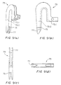
- Anvil 73 which is preferably made of molded plastic or the like, includes a rear portion 73-1 and a front portion 73-2.
- Rear portion 73-1 is disposed within barrel portion 61 of casing 53 and is secured to halves 55 and 57 by screw 70 (anvil 73 sharing screw 70 with door 69).
- Hooked front portion 73-2 extends upwardly from the top of casing 53 and then loops downwardly in front of tool 51 spaced a short distance from opening 62.
- Front portion 73-2 is provided with an opening 75, which is aligned with opening 62 and which is appropriately spaced from tool 51 so as to receive the tip of the needle of tool 51.
- Front portion 73-2 is also provided with an outer slot 77 which is preferably dimensioned depthwise to extend beyond the tip of the needle in its forwardmost position and is preferably dimensioned widthwise to prevent a user from inserting his fingers thereinto.
- anvil 73 not only serves as a support for the fastening operation to be performed by tool 51 but also serves to protect a user from injury caused by accidental needle sticks.
- the spacing between opening 62 of tool and opening 75 of anvil 73 is preferably sufficiently small (e.g., 0,635-0,762 cm (0.25-0.3 inch)) to prevent a user from inserting his fingers therebetween.
- anvil 73 is secured to casing 53 by screw 70. anvil 73 can easily be replaced if damaged. Also, anvil 73 can readily be replaced with an anvil having a different sized loop if one wishes to vary the point of attachment of the fastener dispensed by tool 51 into an object (i.e., generally speaking, the higher the loop, the lower the point of attachment of the fastener into the object).
- tool 51 also includes a triggering mechanism whose purpose will become apparent below.
- said triggering mechanism includes a trigger 81.
- Trigger 81 which may be made of molded plastic or another similarly suitable material, is pivotally attached to casing 53 by a pin 83 and extends partially through an opening 84 formed in handle portion 59 of casing 53 so that it may be digitally manipulated for movement towards and away from, respectively, the rear wall of handle portion 59.
- a coiled spring 85 which is attached at one end to the inside rear wall of handle portion 59 and which is attached at its opposite end to the inside of trigger 81, biases trigger 81 away from the rear wall of handle portion 59.
- the triggering mechanism of tool 51 additionally includes a lever 87 and a float link 89, both of which may be made of molded plastic or another suitable material.
- Lever 87 is disposed within casing 53 and is pivotally mounted at a first end 87-1 on a pin 88, pin 88 being fixed to trigger 81.
- Float link 89 is pivotally mounted at one end on a pin 90 mounted inside handle portion 59 and is pivotally mounted at its opposite end on a pin 91 fixed to an intermediate portion of lever 87.
- Tool 51 further includes a needle assembly.
- said needle assembly comprises a needle 93.
- needle 93 comprises a stem portion 95 and a base portion 97.
- Stem portion 95 which may be made from stamped and rolled metal, is a generally cylindrical member terminating at one end in a sharp tip 95-1 designed for insertion through a garment or like object.
- Stem portion 95 also has a slotted bore 95-2 extending substantially longitudinally thereacross.
- Base portion 97 may be made of a plastic that has been insert-molded onto that end of stem portion 95 that is distal to tip 95-1.
- stem portion 95 and base portion 97 may be a unitary structure made of metal or another suitable material.
- Base portion 97 is provided with a slotted longitudinal bore 97-1 that is aligned with bore 95-2 of stem portion 95 and is also provided with a scallop-shaped recess 99 on its outer surface whose purpose will be described below.
- the bores of stem portion 95 and base portion 97 are appropriately dimensioned so that cross-bar 15 of a fastener 11 may be inserted thereinto from the rear of base portion 97, traverse the length of needle 93 through bore 95-2 and then exit needle 93 via tip 95-1.
- the slots of stem portion 95 and base portion 97 are appropriately dimensioned to permit the filament 13 of fastener 11 to extend therethrough while its associated cross-bar 15 is disposed within needle 93, said slots being oriented in tool 51 so as to face towards half 55 of casing 53.
- the needle assembly of tool 51 further comprises a needle carrier 101 (shown separately in Figs. 11(a) through 11(f)), needle carrier 101 being slidably mounted in a slot 102 defined at least in part by matching sets of longitudinally extending ribs 104-1/104-2 and 106-1/106-2 integrally formed on right half 55 and left half 57, respectively, of casing 53 (ribs 106-1 and 106-2 being visible in Figs. 7(b) and 7(c)).
- One end of a spring 108 is attached to a post 110 formed on needle carrier 101, the opposite end of spring 108 being attached to a post 112 mounted in casing 53. In this manner, needle carrier 101 is normally biased rearwardly in barrel portion 61.
- Needle carrier 101 which may be made of molded plastic or another suitable material, is provided at its front end with a sleeve 107, sleeve 107 being aligned with opening 62 for reasons to become apparent below.
- Base portion 97 of needle 93 is disposed within sleeve 107 and is lockably secured therewithin by a locking pin 109.
- locking pin 109 can be seen to be a generally cylindrical member having a slotted head 111 (manipulable with a screwdriver or the like) at one end thereof, a longitudinally-extending slot 113 at the opposite end thereof and a scallop-shaped recess 115 on its outer surface at about its midpoint. Recess 115 on pin 109 is appropriately dimensioned to receive base portion 97 of needle 93. and recess 99 of base portion 97 is appropriately dimensioned to receive pin 109.
- Locking pin 109 is disposed in a bore 117 formed in carrier 101, bore 117 being shown in Figs. 11(a) through 11(d) and in Fig. 11(f).
- bore 117 and sleeve 107 are oriented relative to one another so that, when pin 109 is rotationally positioned so that recess 115 faces away from needle 93. needle 93 is engaged by pin 109 and, therefore, is locked into sleeve 107 whereas, when pin 109 is rotationally positioned so that recess 115 faces towards needle 93, needle 93 is not engaged by pin 109 and, therefore, is free to be removed from sleeve 107.
- slotted head 111 of locking pin 109 is accessible (for use in locking and unlocking needle 93) through an opening 119 formed in the bottom of barrel portion 61.
- tool 51 further includes a mechanism for loading fasteners, one at a time, into needle 93 and for ejecting loaded fasteners from needle 93.
- said loading/ejecting mechanism comprises an ejector rod carrier 141, an ejector rod 143 and an ejector clip 145.
- Ejector rod carrier 141 (shown separately in Figs. 14(a) and 14(b)), which may be made of molded plastic or another suitable material, is slidably mounted on the underside of needle carrier 101.
- Ejector rod carrier 141 is coupled to lever 87 by means of a pin 147 that is fixed to ejector rod carrier 141, lever 87 being pivotally mounted on pin 147.
- the top of carrier 141 is shaped to include a first recessed portion 149-1 at its front end and a second recessed portion 149-2 proximate to its rear end.
- Ejector rod 143 is preferably conventional in shape and composition.
- the rear end of ejector rod 143 is mounted in the front end of carrier 141, the front end of ejector rod 143 extending forwardly away from carrier 141 and being aligned with bore 97-1 of needle 93.
- ejector rod carrier 141 and ejector rod 143 together move forwardly through barrel portion 61 until the front end of ejector rod 143 is inserted completely through needle 93.
- the cross-bar 15 of the lead fastener11 of a fastener clip 31 loaded in tool 51 is positioned behind bore 97-1 of needle 93, as the front end of ejector rod 143 moves forwardly through barrel portion 61, it pushes said cross-bar into and through needle 93, in the process severing the connector 33 between said cross-bar and its adjacent cross-bar 15
- Ejector clip 145 which is shown separately in Fig. 15, is preferably a unitary structure made of stamped stainless steel or the like.
- Clip 145. which is positioned between the right side of ejector carrier 141 and the inner right side of needle carrier 101, is shaped to include a front portion 151-1 and a rear portion 151-2.
- Front portion 151-1 is provided with a tip 152, tip 152 being aligned with cross-bar 17 of the lead fastener 11.
- Rear portion 151-2 is provided with an elongated slot 153 through which pin 147 extends. As can be seen best in Fig. 15, the rear end 153-1 of slot 153 is angled upwardly.
- pin 147 begins to move forwardly through slot 153 from rear end 153-1, causing clip 145 to be moved forwardly a short distance and causing tip 152 of clip 145 to engage cross-bar 17 of the lead fastener and to push it forwardly until the connector 35 connecting cross-bar 17 to the remainder of the clip 31 breaks.
- pin 147 moves through the straight front end 153-2 of slot, causing clip 145 to remain stationary while carrier 141 moves forwardly.
- pin 147 moves rearwardly through slot 153, and clip 145 is restored to its original position.
- tool 51 further comprises a mechanism for coupling and decoupling ejector rod carrier 141 to and from needle carrier 101.
- said mechanism comprises a linking member 161 (shown separately in Fig. 16).
- Linking member 161 which may be made of molded plastic or a similarly suitable material, is seated in a slot 142 (shown best in Figs. 11(a) and 11(b)) formed in needle carrier 101 and is pivotally mounted at one end 161-1 to needle carrier 101 by a pin 163.
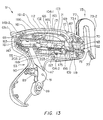
- linking member 161 As seen best in Fig. 13, the front end 161-2 of linking member 161 is enlarged and, prior to actuation of trigger 81, is disposed over the recessed portion 149-1 of carrier 141.
- trigger 81 When trigger 81 is first squeezed, carrier 141 moves forwardly; however, because of recessed portion 149-1, carrier 141 does not initially engage the enlarged front end 161-2 of linking member 161.
- linking member 161 and, in turn, needle carrier 101 are not initially coupled to carrier 141 and do not initially move forwardly with carrier 141.
- ejector rod 143 severs the lead cross-bar 15 from its adjacent cross-bar 15 and feeds the lead cross-bar 15 into needle 93.
- trigger 81 causes that portion of carrier 141 located immediately behind recessed portion 149-1 to pivotfront end 161-2 of linking member 161 up against rib 104-1, thereby causing linking member 161 and, in turn, needle carrier 101 to be coupled to carrier 141.
- carrier 101, linking member 161 and carrier 141 begin to move forwardly together through slot 102.
- needle 93 and ejector rod 143 move together, with tip 95-1 of needle 93 passing through opening 62 of casing 53 and through opening 75 of anvil 73.
- linking member 161 and carrier 141 are decoupled as front end 161-2 of linking member 161 arrives at and is forced through an opening 165 formed in rib 104-1 (a corresponding opening being provided in rib 106-1) while carrier 141 continues to move forwardly through barrel portion 61.
- ejector rod 143 continues to move forwardly through the now-stationary needle 93.
- trigger 81 causes ejector carrier 141 to slide across the now-stationary enlarged end 161-2 of member 161 until enlarged end 161-2 drops down into recessed portion 149-2 of carrier 141.
- ejector rod 143 completes its forward progress through needle 93.
- carrier 141 and member 161 move rearwardly together (with enlarged end 161-2 disposed in recessed portion 149-2 and pressed up against rib 104-1) until member 161 is fully withdrawn and enlarged end 161-2 is aligned with an opening 166 in rib 104-1 (a corresponding opening being provided in rib 106-1).
- ejector rod 143 and needle 93 move rearwardly together, with needle 93 being completely withdrawn into casing 53 through opening 62.
- trigger 81 causes carrier 141 to slide rearwardly across the now-stationary enlarged end 161-2 until carrier 141 is fully withdrawn and enlarged end 161-2 is returned to its starting position over recessed portion 149-1.
- ejector rod 143 fully retracts.
- Tool 51 further comprises a feed track 171 along which a fastener clip 31 may be advanced through tool 51 to a position where individual fasteners can be loaded into and dispensed from needle 93.
- Feed track 171 which extends from the rear of opening 68 to just behind bore 97-1 of needle 93, is defined, in part, by a matching pair of arcuate ribs 173-1 and 173-2 formed interiorly along the barrel portion of halves 55 and 57, respectively, and is defined, in part, by a feed guide 175 (shown separately in Figs. 17(a) through 17(c)) stationarily mounted in barrel portion 61 just behind needle 93.
- Feed track 171 is appropriately dimensioned so that the entirety of a clip analogous to clip 31 but comprising one hundred twenty-five fasteners 11 can be completely contained within tool 51. As can readily be appreciated, even longer fastener clips (e.g., clips having several hundred fasteners 11) can be disposed in feed track 171, with the rear end of such clips extending out through opening 68 of tool 51.
- fastener clips e.g., clips having several hundred fasteners 11
- feed guide 175. which is preferably a unitary structure made of molded plastic or the like, is shaped to include a front portion 177-1, a rear portion 177-2 and an intermediate portion 177-3.
- Front portion 177-1 is provided with a slotted bore 179, which is aligned with bore 97-1 of needle 93 and which is also aligned with ejector rod 143, and is also provided with a slot 180, which is aligned with tip 152 of clip 145.
- the front surface of front portion 177-1 is shaped to include a recessed area 181, which is adapted to receive the rear of base portion 97 of needle 93 as needle 93 is moved back and forth by needle carrier 101.
- the rear surface of front 177-1 is shaped to include a guide rib 183, guide rib 183 being positioned in feed track 171 and being appropriately dimensioned to keep cross-bars 15 and 17 properly aligned on opposite sides thereof as a clip 31 travels downwardly through feed track 171.
- a downwardly and outwardly angled bump 183-1 is provided on rib 183, bump 183-1 being positioned on rib 183 and appropriately dimensioned so that the filament 15 of the lead fastener 11 slides thereacross as said fastener moves into position to be dispensed but, once drawn past bump 183-1, cannot easily be pulled back thereover.
- bump 183-1 acts as an anti-back to prevent a clip 31 from moving backwards in feed track 171 during the as yet to be described feeding operation of the clip.
- the top surface of intermediate portion 177-3 constitutes the front end of feed track 171 and functions as a stage on which the lead fastener 11 of clip 31 is situated prior to being dispensed by tool 51.
- a pair of transverse openings 185-1 and 185-2 are provided in rear portion 177-2 of guide 175, opening 185-1 being positioned so that it is aligned both with ejector rod 143 and with bore 179, opening 185-2 being positioned so that it is aligned with tip 152 of clip 145 and with slot 180.
- one advantage to having connectors 33 and 35 taper in the manner described above is that, once connectors 33 and 35 between the lead fastener and its adjacent fastener have been severed and the lead fastener has been dispensed, the cross-bars 15 and 17 of the adjacent fastener are capable of sitting substantially flush on top of the top surface of portion 177-3.
- cross-bars 37 and 39 ensure that cross-bars 15 and 17 of the last fastener 11 of clip 31 remain properly aligned with bore 179 and slot 180, respectively.
- tool 51 further comprises a feed clip 187, clip 187 being mounted on guide 175 for use in maintaining the alignment of cross-bar 15 of the lead fastener 11 with bore 179 while said cross-bar 15 is seated on top of portion 177-3 of guide 175.
- clip 187 is a unitary structure, preferably made of molded plastic, comprising a main portion 189-1 and an arm 189-2.
- Main portion 189-1 is provided with a pair of mounting posts 190-1 and 190-2 insertable into a pair of corresponding openings 191-1 and 191-2 formed in guide 175.
- Arm 189-2 which is biased away from main portion 189-1, is shaped to include a finger 192 adapted to engage cross-bar 15 of the lead fastener 11.
- tool 51 further comprises a mechanism for feeding or advancing a clip 31 through feed track 171 at a rate of one fastener per trigger stroke.
- said feeding or advancing mechanism comprises a pawl 193 made of molded plastic or a similarly suitable material.
- Pawl 193 which is shaped to include a pair of fingers 194-1 and 194-2 (see Fig. 19) engageable with the filament portion 15 of a clip 31 seated in guide 175, is rotatably mounted on guide 175 by a pin 195.
- pawl 193 is mechanically coupled by a wire hook 197 to a feed sliding member 199 (shown separately in Fig.
- a rear post 207 is formed at the rear end of member 199, and a front post 209 is formed proximate to the front end of member 199.
- Posts 207 and 209 are appropriately positioned on member 199 so that, when trigger 81 is nearly completely squeezed, lever 87 contacts post 209 and moves member 1.99 forwardly a short distance. This causes pawl 193 to rotate away from the fasteners positioned in guide 175.
- lever 87 contacts post 207 and moves member 199 rearwardly a short distance. This causes pawl 193 to rotate towards the fasteners positioned in guide 175,whereby fingers 194-1 and 194-2 engage the filament portion of the clip and pull the clip down to advance it by one fastener.
- clip 31 (or more preferably a fastener clip analogous to clip 31 but comprising on the order of one hundred twenty-five fasteners 11) is loaded into tool 51. This is typically done by opening door 69, inserting the clip into feed track 171 (i.e., by orienting the clip relative to ribs 173-1 and 173-2 so that the respective filaments 15 are disposed on top of and across ribs 173-1 and 173-2 and so that the respective cross-bars 15 and 17 are positioned off to the sides of and perpendicular to ribs 173-1 and 173-2), closing door 69, and advancing the clip through feed track 171 using wheel 71.
- feed track 171 i.e., by orienting the clip relative to ribs 173-1 and 173-2 so that the respective filaments 15 are disposed on top of and across ribs 173-1 and 173-2 and so that the respective cross-bars 15 and 17 are positioned off to the sides of and perpendicular to ribs 173-1 and 173-2
- a fastener 11 may be inserted into a desired article first by placing the article between opening 62 in casing 53 and opening 75 in anvil 73 (arrows 67-1 and 67-2 optionally being used to locate openings 62 and 75) and then by squeezing and releasing trigger 81 in the manner described above.
Landscapes
- Physics & Mathematics (AREA)
- General Physics & Mathematics (AREA)
- Engineering & Computer Science (AREA)
- Theoretical Computer Science (AREA)
- Surgical Instruments (AREA)
- Clamps And Clips (AREA)
- Labeling Devices (AREA)
Claims (33)
- Tragbare Befestigungselement-Ausgabevorrichtung (51) zur Ausgabe eines Befestigungselements des Typs, der einen flexiblen Faden (13) umfasst, welcher eine Verlängerung an seinem einen Ende besitzt, wobei die Befestigungselement-Ausgabevorrichtung (51) umfasst:(a) ein Gehäuse (53), wobei das genannte Gehäuse (53) ausgestattet ist mit einer Öffnung für eine Nadel (93);(b) einer hohlen, geschlitzten Nadel (93), wobei die genannte hohle, geschlitzte Nadel (93) verschiebbar rückwärts und vorwärts zwischen einer zurückgezogenen Position, die vollständig innerhalb des genannten Gehäuses (53) angeordnet ist, und einer ausgefahrenen Position, die sie sich durch die genannte Öffnung für die Nadel (93) erstreckt, bewegbar ist, wobei die genannte hohle, geschlitzte Nadel (93) angepasst ist, um die Verlängerung des genannten Befestigungselements (11) aufzunehmen;(c) eine Auswurfstange (143), wobei die genannte Auswurfstange (143) verschiebbar rückwärts und vorwärts durch die genannte hohle, geschlitzte Nadel (93) bewegbar ist, um die darin untergebrachte Verlängerung auszuwerfen; und(d) ein Amboss (73), das relativ zu dem genannten Gehäuse (53) fixiert ist und sich vor der genannten Öffnung für die Nadel (93) erstreckt, wobei der genannte Amboss (73) so positioniert ist, dass sich die genannte hohle, geschlitzte Nadel (93), wenn sie sich in der genannten ausgefahrenen Position befindet, nicht darüber hinaus erstreckt.
- Tragbare Befestigungselement-Ausgabevorrichtung (51), wie in Anspruch 1 beansprucht, worin das genannte Gehäuse (53) revolverförmig ist und einen Lauf-Teil (61) und einen Griff-Teil (59) umfasst.
- Tragbare Befestigungselement-Ausgabevorrichtung (51), wie in Anspruch 2 beansprucht, worin der genannte Griff-Teil (59) mit einer Auslöseröffnung (87) ausgestattet ist, wobei die genannte Befestigungselement-Ausgabevorrichtung (51) weiterhin einen Auslöser (81) umfasst, wobei der genannte Auslöser (81) drehbar in dem genannten Gehäuse (53) befestigt ist und sich teilweise durch die genannte Auslöseröffnung (87) für seine digitale Betätigung erstreckt, der genannte Auslöser (81) an die genannte hohle, geschlitzte Nadel (93) gekoppelt ist und auch an die genannte Auswurfstange (143) gekoppelt ist.
- Tragbare Befestigungselement-Ausgabevorrichtung (51), wie in Anspruch 3 beansprucht, die weiterhin einen Auswurfstangen-Träger (141) umfasst, der in dem genannten Lauf-Teil (61) des genannten Gehäuses (53) angeordnet ist, wobei die genannte Auswurfstange (143) auf dem genannten Auswurfstangen-Träger (141) befestigt ist, der genannte Auswurfstangen-Träger (141) mit dem genannten Auslöser (81) derart verbunden ist, dass bewirkt wird, dass sich der genannte Auswurfstangen-Träger rückwärts und vorwärts durch den genannten Lauf-Teil (61) bewegt, wenn der Auslöser (81) betätigt wird.
- Tragbare Befestigungselement-Ausgabevorrichtung (51), wie in Anspruch 4 beansprucht, weiterhin einen Nadelträger (101) umfassend, der in dem genannten Lauf-Teil (61) des genannten Gehäuses (53) angeordnet ist, wobei die genannte hohle, geschlitzte Nadel (93) auf dem genannten Nadelträger (101) befestigt ist, die genannte tragbare Befestigungselement-Ausgabevorrichtung (51) weiterhin eine Verbindung umfasst, die an den genannten Nadelträger (101) gekoppelt ist und selektiv verbindbar ist mit dem genannten Auswurfstangen-Träger (141) zur Kopplung und Entkopplung des genannten Nadelträgers (101) an und von dem genannten Auswurfstangen-Träger (141), so dass bewirkt wird, dass sich der genannte Nadelträger (101) rückwärts und vorwärts in dem genannten Lauf-Teil (61) nur während eines Teils der Bewegung des genannten Auswurfstangen-Trägers (141) bewegt.
- Tragbare Befestigungselement-Ausgabevorrichtung (51), wie in Anspruch 5 beansprucht, die weiterhin einen Hebel (87) umfasst, der innerhalb des genannten Gehäuses (53) angeordnet ist, wobei der genannte Hebel (87) drehbar befestigt ist an einem ersten Ende eines ersten Stifts (91), der genannte erste Stift (91) an dem genannten Auslöser (81) fixiert ist, wobei der genannte Hebel (87) drehbar befestigt ist an einem zweiten Ende an einem zweiten Stift (147), wobei der zweite Stift (147) an dem genannten Auswurfstangen-Träger (141) fixiert ist.
- Tragbare Befestigungselement-Ausgabevorrichtung (51), wie in Anspruch 5 beansprucht, weiterhin eine Beschickungsbahn (171) umfassend, die innerhalb des LaufTeils (61) des genannten Gehäuses (53) angeordnet ist, wobei die genannte Beschickungsbahn (171) geformt ist, um, vollständig innerhalb dem genannten Lauf-Teil (61), eine Klammer von Befestigungselementen (11) aufzunehmen, wobei jedes der genannten Befestigungselemente (11) einen flexiblen Faden (13), ein erste Verlängerung an einem Ende des flexiblen Fadens und eine zweite Verlängerung an dem anderen Ende des flexiblen Fadens (13) umfasst.
- Tragbare Befestigungselement-Ausgabevorrichtung (51), wie in Anspruch 7 beansprucht, worin die genannte Beschickungsbahn (171) teilweise definiert ist durch eine Beschickungsführung (175), die innerhalb des genannten Gehäuses (53) angeordnet ist, und teilweise durch eine Rippe, die im Innenbereich des genannten Gehäuses (53) ausgebildet ist.
- Tragbare Befestigungselement-Ausgabevorrichtung (51), wie in Anspruch 1 beansprucht, worin der genannte Amboss (73) einen Vorderteil (73-2) und einen Rückteil (73-1) umfasst, der genannte Rückteil (73-1) an dem genannten Gehäuse (53) gesichert ist, der genannte Vorderteil (73-2) gebogen ist und sich vor der genannten Öffnung (62) in dem genannten Gehäuse (53) erstreckt.
- Tragbare Befestigungselement-Ausgabevorrichtung (51), wie in Anspruch 9 beansprucht, worin der genannte Vorderteil (73-2) des genannten Ambosses (73) mit einer Amboss-Öffnung (75) versehen ist, wobei die genannte Amboss-Öffnung (75) mit der genannten Öffnung (62) in dem genannten Gehäuse (53) fluchtet, wobei der genannte Vorderteil des genannten Ambosses (73) auch mit einer geschlitzten äußeren Oberfläche versehen ist.
- Tragbare Befestigungselement-Ausgabevorrichtung (51), wie in Anspruch 10 beansprucht, worin die genannte Amboss-Öffnung (75) und die genannte Öffnung (62) in dem genannten Gehäuse (53) mit einer Distanz von ungefähr 0,635 - 0,762 cm (0,25 - 0,3 Inch) voneinander beabstandet sind.
- Tragbare Befestigungselement-Ausgabevorrichtung (51), wie in Anspruch 9 beansprucht, worin der genannte Rückteil (73-1) des genannten Ambosses (73) mittels einer Schraube (70) entfernbar gesichert ist an dem genannten Gehäuse (53).
- Befestigungselement-Ausgabevorrichtung (51), wie in Anspruch 6 beansprucht, worin die genannte Nadel (93) mittels eines Arretierstifts (109) entfernbar gekoppelt ist an den genannten Nadelträger (101).
- Befestigungselement-Ausgabevorrichtung (51), wie in Anspruch 13 beansprucht, worin der genannte Lauf-Teil (61) des genannten Gehäuses (53) mit einer Öffnung versehen ist, um den Arretierstift (109) zugänglich zu machen.
- Befestigungselement-Ausgabevorrichtung (51), wie in den Ansprüchen 1 bis 14 beansprucht, worin das genannte Gehäuse (53) revolverförmig ist und einen Griff-Teil (59) und einen Lauf-Teil (61) einschließt, die genannte Befestigungselement-Ausgabevorrichtung (51) weiterhin einen Nadelträger (101), einen Auswurfstangen-Träger (141), ein Verbindungselement und einen Auslösermechanismus umfasst, wobei der genannte Nadelträger (101) verschiebbar in dem genannten Lauf-Teil (61) befestigt ist, die genannte hohle, geschlitzte Nadel (93) an den genannten Nadelträger (101) gekoppelt ist, der genannte Auswurfstangen-Träger (141) verschiebbar in dem genannten Lauf-Teil (61) befestigt ist, die genannte Auswurfstange (143) an den genannten Auswurfstangen-Träger (141) gekoppelt ist, das genannte Verbindungselement an den genannten Nadelträger (101) gekoppelt ist und selektiv verbindbar ist mit dem genannten Auswurfstangen-Träger (141) zur Kopplung und Entkopplung des genannten Nadelträgers (101) vom genannten Auswurfstangen-Träger (141), so dass bewirkt wird, dass der genannte Nadelträger (101) nur während eines Teils der Bewegung des genannten Auswurfstangen-Trägers (141) in dem genannten Lauf-Teil (61) zurück und vorwärts rutscht, wobei der Auslösermechanismus einen Auslöser (81) umfasst, der genannte Auslöser (81) in dem genannten Gehäuse (53) drehbar befestigt ist und sich teilweise durch dessen genannten Griff-Teil (59), zur manuellen Betätigung, erstreckt, wobei der genannte Auslösemechanismus weiterhin einen Hebel (87) umfasst, der innerhalb des genannten Gehäuses (53) angeordnet ist, der genannte Hebel (87) drehbar befestigt ist an einem ersten Ende eines ersten Stifts (91), wobei der genannte erste Stift (91) an dem genannten Auslöser (81) fixiert ist, der genannte Hebel (87) drehbar befestigt ist an einem zweiten Ende eines zweiten Stifts (147), wobei der genannte zweite Stift (147) an dem genannten Auswurfstangen-Träger (141) fixiert ist.
- Befestigungselement-Ausgabevorrichtung (51), wie in Anspruch 15 beansprucht, weiterhin einen Amboss (73) umfassend, wobei der Amboss (73) an das genannte Gehäuse (53) gekoppelt ist.
- Befestigungselement-Ausgabevorrichtung (51), wie in Anspruch 15 beansprucht, worin der genannte Amboss (73) entfernbar an das genannte Gehäuse (53) gekoppelt ist.
- Befestigungselement-Ausgabevorrichtung (51), wie in Anspruch 15 beansprucht, worin die genannte Befestigungselement-Ausgabevorrichtung (51) angepasst ist für die Ausgabe einzelner Befestigungselemente (11) aus einer Befestigungselement-Klammer (31), die einzelnen Befestigungselemente (11) einen flexiblen Faden (13) umfassen, der eine erste Verlängerung an einem ersten Ende davon und eine zweite Verlängerung an einem zweiten Ende davon besitzt, wobei benachbarte erste Verlängerungen der genannten Befestigungselement-Klammer (31) verbunden sind durch einen ersten Verbindungssteg (35), die benachbarte zweite Verlängerung der genannten Befestigungselement-Klammer (31) verbunden ist durch einen zweiten Verbindungssteg (35), die genannten ersten Verlängerungen der genannten Klammer (31) ausgegeben werden durch die genannte hohle, geschlitzte Nadel (93), wobei die genannte Befestigungselement-Ausgabevorrichtung (51) weiterhin eine Auswurfklammer (145) umfasst, die an den genannten Auswurfstangen-Träger (141) gekoppelt ist, um den zweiten Verbindungssteg (35) zwischen benachbarten zweiten Verlängerungen zu trennen.
- Befestigungselement-Ausgabevorrichtung (51), wie in den Ansprüchen 1 bis 11 beansprucht, weiterhin eine Beschickungsführung (175) umfassend, wobei die genannte Beschickungsführung (175) feststehend in dem genannten Gehäuse (53) hinter der genannten hohlen, geschlitzten Nadel (93) befestigt ist, die genannte Beschickungsführung (175) einen Vorderteil einer Beschickungsbahn (171) definiert und eine Stufe am Ende der genannten Beschickungsbahn (171) umfasst, von welcher entfernt ein einzelnes Befestigungselement (11) aus einer Befestigungselement-Klammer (31) in die genannte hohle, geschlitzte Nadel (93) mittels der genannten Auswurfstange (143) geladen wird.
- Befestigungselement-Ausgabevorrichtung (51), wie in Anspruch 15 beansprucht, worin die genannte Beschickungsführung (175) weiterhin einen Vorsprung umfasst, der mit dem Fadenteil einer Verbindungselement-Klammer (31) verbindbar ist, verwendbar um zu verhindern, dass sich die genannte Befestigungselement-Klammer (31) rückwärts in die genannte Beschickungsbahn (171) bewegt.
- Befestigungselement-Ausgabevorrichtung (51), wie in Anspruch 15 beansprucht, worin die genannte Beschickungsführung (175) mit einem vertieften Teil versehen ist, der eine geschlitzte Bohrung (179) besitzt, wobei der genannte vertiefte Teil angepasst ist, um entfernbar die genannte hohle, geschlitzte Nadel (93) aufzunehmen.
- Befestigungselement-Ausgabevorrichtung (51), wie in Anspruch 15 beansprucht, worin das genannte Gehäuse innen geformt ist, um einen Rückteil (177-2) einer Beschickungsbahn (171) zu definieren, wobei der genannte Rückteil (177-2) mit dem genannten Vorderteil (177-1) der genannten Beschickungsbahn (171) fluchtet.
- Befestigungselement-Ausgabevorrichtung (51), wie in Anspruch 22 beansprucht, worin die genannte Beschickungsbahn (171) geformt ist, um vollständig innerhalb des genannten Gehäuses (53) eine Vielzahl von Befestigungselementen (11) aufzunehmen.
- Befestigungselement-Ausgabevorrichtung (51), wie in Anspruch 23 beansprucht, weiterhin eine Tür (69) umfassend, die drehbar an dem genannten Gehäuse (53) befestigt ist, wobei die genannte Tür (69) einen Zugriff auf die genannte Beschickungsbahn (171) bereitstellt.
- Befestigungselement-Ausgabevorrichtung (51), wie in Anspruch 24 beansprucht, weiterhin ein Rad umfassend, das rotierbar in der genannten Tür (69) befestigt ist, wobei das genannte Rad angepasst ist, um eine Befestigungselement-Klammer (31) einzurasten, die in der genannten Beschickungsbahn (171) angeordnet ist.
- Befestigungselement-Ausgabevorrichtung (51), wie in Anspruch 15 beansprucht, worin das genannte Gehäuse (53) mit einem Paar Fenster (65) ausgestattet ist, zur Verwendung bei der Beobachtung einer Befestigungselement-Klammer (31), die in der genannten Beschickungsbahn (171) angeordnet ist.
- Befestigungselement-Ausgabevorrichtung (51), wie in Anspruch 15 beansprucht, weiterhin umfassend einen Auslösemechanismus, der in dem genannten Gehäuse (53) angebracht ist, einen Mechanismus, der den genannten Auslösemechanismus zur Bewegung der genannten hohlen, geschlitzten Nadel (93) koppelt, und einen Mechanismus, der den genannten Auslösemechanismus zur Bewegung der genannten Auswurfstange (143) koppelt.
- Befestigungselement-Ausgabevorrichtung (51), wie in Anspruch 27 beansprucht, weiterhin einen Mechanismus umfassend zum Vorschieben einer Befestigungselement-Klammer (31) durch die genannte Beschickungsbahn (171) mit einer Rate von einem Befestigungselement (11) pro Auslöserzug.
- Befestigungselement-Ausgabevorrichtung (51), wie in den Ansprüchen 1 bis 19 beansprucht, worin die genannte Auswurfstange (143) verschiebbar rückwärts und vorwärts bewegbar ist zwischen einer zurückgezogenen Position, die hinter der genannten hohlen, geschlitzten Nadel (93) angeordnet ist, und einer vorgerückten Position, die sich durch die genannte hohle, geschlitzte Nadel (93) erstreckt, die genannte Befestigungselement-Ausgabevorrichtung weiterhin umfassend einen Auslöser (81), der mechanisch an das genannte Gehäuse (53) gekoppelt ist,
erste Kopplungsmittel, welche den genannten Auslöser (81) an die genannte hohle, geschlitzte Nadel (93) koppeln, zur Bewegung der genannten hohlen, geschlitzten Nadel (93) von der genannten zurückgezogenen Position zu der genannten vorgerückten Position, und dann zurück zu der genannten zurückgezogenen Position, während eines Auslöserzugs, und
zweite Kopplungsmittel, welche den genannten Auslöser (81) an die genannte Auswurfstange (143) koppeln, zur Bewegung der genannte Auswurfstange (143) von der genannten zurückgezogenen Position zu der genannten vorgerückten Position, und dann zurück zu der genannten zurückgezogenen Position, während eines Auslöserzugs,
worin die genannten ersten Kopplungsmittel und die genannten zweiten Kopplungsmittel so gestaltet sind, dass die genannte Auswurfstange (143) sich von der genannten vorgerückten Position zusammen mit der genannten hohlen, geschlitzten Nadel (93) zurückzieht, wenn sich die genannte hohle, geschlitzte Nadel (93) von der genannten vorgerückten Position zu der genannten zurückgezogenen Position bewegt. - Befestigungselement-Ausgabevorrichtung (51), wie in den Ansprüchen 1 bis 29 beansprucht, worin das genannte Gehäuse (53) gestaltet ist, um vollständig innerhalb des genannten Gehäuses (53) eine Klammer (31) von Befestigungselementen (11) aufzunehmen, wobei jedes der Befestigungselemente (11) in der genannten Klammer (31) einen flexiblen Faden (13) umfasst, der einen ersten verlängerten Teil an einem ersten Ende davon und einen zweiten verlängerten Teil an einem zweiten Ende davon besitzt.
- Befestigungselement-Ausgabevorrichtung (51), wie in Anspruch 30 beansprucht, worin das genannte Gehäuse (53) geformt ist, um vollständig darin eine Klammer (31) mit ungefähr einhundertfünfundzwanzig Befestigungselementen (11) aufzunehmen.
- Befestigungselement-Ausgabevorrichtung (51), wie in Anspruch 30 beansprucht, worin die genannte Beschickungsbahn (171) hinter der genannten hohlen, geschlitzten Nadel (93) in einer Richtung abschließt, die im Wesentlichen lotrecht auf die longitudinale Achse der genannten hohlen, geschlitzten Nadel (93) ist.
- Befestigungselement-Ausgabevorrichtung (51), wie in Anspruch 32 beansprucht, worin das genannte Gehäuse (53) geformt ist, um darin vollständig eine Klammer mit ungefähr einhundertfünfundzwanzig Befestigungselementen (11) aufzunehmen.
Applications Claiming Priority (7)
| Application Number | Priority Date | Filing Date | Title |
|---|---|---|---|
| US12255799P | 1999-03-02 | 1999-03-02 | |
| US122557P | 1999-03-02 | ||
| US09/483,180 US6267285B1 (en) | 1998-07-15 | 2000-01-13 | Plastic fastener, fastener clip, fastener dispensing tool and method of fastening objects |
| US483180 | 2000-01-13 | ||
| US09/483,181 US6418597B1 (en) | 1998-07-15 | 2000-01-13 | Plastic fastener, fastener clip, fastener dispensing tool and method of fastening objects |
| US483181 | 2000-01-13 | ||
| PCT/US2000/005649 WO2000051792A2 (en) | 1999-03-02 | 2000-03-02 | Plastic fastener, fasterner clip, fastener dispensing tool and method of fastening objects |
Publications (3)
| Publication Number | Publication Date |
|---|---|
| EP1204337A2 EP1204337A2 (de) | 2002-05-15 |
| EP1204337A4 EP1204337A4 (de) | 2002-08-28 |
| EP1204337B1 true EP1204337B1 (de) | 2006-12-27 |
Family
ID=46203816
Family Applications (1)
| Application Number | Title | Priority Date | Filing Date |
|---|---|---|---|
| EP00916055A Expired - Lifetime EP1204337B1 (de) | 1999-03-02 | 2000-03-02 | AUSGABEVORRICHTUNG FüR KUNSTSTOFF-BEFESTIGUNGSELEMENTE |
Country Status (5)
| Country | Link |
|---|---|
| EP (1) | EP1204337B1 (de) |
| AU (1) | AU3721900A (de) |
| CA (1) | CA2365028C (de) |
| DE (1) | DE60032613T2 (de) |
| WO (1) | WO2000051792A2 (de) |
Families Citing this family (4)
| Publication number | Priority date | Publication date | Assignee | Title |
|---|---|---|---|---|
| US6564984B1 (en) * | 2000-04-27 | 2003-05-20 | M.I.T. International Co., Ltd. | Loop pin connecting device |
| US7654618B2 (en) | 2005-04-08 | 2010-02-02 | Tk Holdings Inc. | Webbing tack |
| US8936184B2 (en) | 2010-02-11 | 2015-01-20 | Avery Dennison Corporation | Plastic fastener dispensing hand tool having a novel anvil design |
| US10196166B2 (en) * | 2016-10-18 | 2019-02-05 | Avery Dennison Corporation | Method of penetrating material with a fastener dispensing needle |
Family Cites Families (22)
| Publication number | Priority date | Publication date | Assignee | Title |
|---|---|---|---|---|
| US3103666A (en) * | 1961-12-28 | 1963-09-17 | Dennison Mfg Co | Tag attaching apparatus |
| BE651540A (de) * | 1963-09-04 | 1964-12-01 | ||
| US3494004A (en) * | 1968-03-28 | 1970-02-10 | Dennison Mfg Co | Attachment for buttons,etc. |
| BE792298A (fr) * | 1972-05-25 | 1973-03-30 | Dennison Mfg Co | Perfectionnements aux attaches pour la reunion de deux objets ensemble |
| US4039078A (en) * | 1973-04-04 | 1977-08-02 | Dennison Manufacturing Company | Fastener attachment stock |
| US4456123A (en) * | 1979-08-31 | 1984-06-26 | Dennison Manufacturing Company | Method and apparatus for dispensing fasteners |
| US4456161A (en) * | 1979-08-31 | 1984-06-26 | Dennison Manufacturing Company | Method and apparatus for dispensing fasteners |
| JPS6024009B2 (ja) * | 1980-09-11 | 1985-06-11 | 株式会社トスカ | 取付部片集合体 |
| US4533076A (en) * | 1981-11-25 | 1985-08-06 | Dennison Manufacturing Company | Dispensing of attachments |
| US4534464A (en) * | 1982-12-08 | 1985-08-13 | Nypro Inc. | Manufacture and use of closely spaced attachments |
| KR850001851B1 (ko) * | 1984-01-21 | 1985-12-28 | 원용권 | 파스너 조립체 및 그 제조방법 |
| JPS60240629A (ja) * | 1984-05-04 | 1985-11-29 | 株式会社 トスカ | 係止具集合体 |
| US4901854A (en) * | 1988-09-29 | 1990-02-20 | Dennison Manufacturing Company | Loop connected attachments |
| US5024365A (en) * | 1989-09-15 | 1991-06-18 | Dennison Manufacturing Company | Apparatus for dispensing fasteners |
| US5205458A (en) * | 1992-03-27 | 1993-04-27 | Steven Kunreuther | Button attacher with variable needle spacing |
| US5321872A (en) * | 1992-09-21 | 1994-06-21 | Avery Dennison Corporation | Tamper-resistant plastic fastener for use in attaching a tag to a piece of fabric |
| US5339954A (en) * | 1993-01-29 | 1994-08-23 | Steven Kunreuther | Clip of attachments |
| US5463799A (en) * | 1993-07-08 | 1995-11-07 | R. William Graham | Fastener for connecting materials with weakened portion |
| US5810238A (en) * | 1994-09-28 | 1998-09-22 | Kunreuther; Steven | Attachments for double needle attacher |
| US5772073A (en) * | 1996-04-10 | 1998-06-30 | Avery Dennison Corporation | Apparatus for dispensing individual plastic fasteners from fastener stock |
| US5683025A (en) * | 1996-05-03 | 1997-11-04 | Avery Dennison Corporation | Apparatus for dispensing individual plastic fasteners from fastener stock |
| US6026544A (en) * | 1998-04-02 | 2000-02-22 | Avery Dennison Corporation | Loop fastener, fastener clip including same and loop fastener dispensing tool |
-
2000
- 2000-03-02 WO PCT/US2000/005649 patent/WO2000051792A2/en not_active Ceased
- 2000-03-02 EP EP00916055A patent/EP1204337B1/de not_active Expired - Lifetime
- 2000-03-02 DE DE60032613T patent/DE60032613T2/de not_active Expired - Lifetime
- 2000-03-02 AU AU37219/00A patent/AU3721900A/en not_active Abandoned
- 2000-03-02 CA CA002365028A patent/CA2365028C/en not_active Expired - Fee Related
Also Published As
| Publication number | Publication date |
|---|---|
| DE60032613D1 (de) | 2007-02-08 |
| EP1204337A2 (de) | 2002-05-15 |
| DE60032613T2 (de) | 2007-11-15 |
| WO2000051792A2 (en) | 2000-09-08 |
| EP1204337A4 (de) | 2002-08-28 |
| CA2365028A1 (en) | 2000-09-08 |
| AU3721900A (en) | 2000-09-21 |
| CA2365028C (en) | 2005-02-01 |
| WO2000051792A9 (en) | 2002-05-02 |
| WO2000051792A3 (en) | 2001-03-08 |
Similar Documents
| Publication | Publication Date | Title |
|---|---|---|
| US6418597B1 (en) | Plastic fastener, fastener clip, fastener dispensing tool and method of fastening objects | |
| US6267285B1 (en) | Plastic fastener, fastener clip, fastener dispensing tool and method of fastening objects | |
| EP1409349B1 (de) | Befestigungsklemme | |
| AU682437B2 (en) | Fastener attaching tool | |
| US7472813B2 (en) | Tool for dispensing plastic fasteners | |
| US5020713A (en) | Assembly of attachments and device for attaching same | |
| USRE34891E (en) | Assembly of attachments and device for attaching same | |
| EP1204337B1 (de) | AUSGABEVORRICHTUNG FüR KUNSTSTOFF-BEFESTIGUNGSELEMENTE | |
| CA2337769C (en) | Fastener clip | |
| US6837413B1 (en) | Plastic fastener, fastener clip, fastener dispensing tool and method of fastening objects | |
| US6009997A (en) | Loop fastener, fastener clip including same and loop fastener dispensing tool | |
| US6752307B2 (en) | Apparatus for dispensing plastic fasteners and needle lock therefor | |
| EP0474938A1 (de) | Gruppe von Befestigungselementen und Vorrichtung zu deren Anbringung | |
| JP2004531432A (ja) | ファスナ・ストックから個々のプラスチック製ファスナを分配する装置 | |
| WO2005005265A2 (en) | Tool for dispensing plastic fasteners | |
| HK1075235B (en) | Tool for dispensing plastic fasteners |
Legal Events
| Date | Code | Title | Description |
|---|---|---|---|
| PUAI | Public reference made under article 153(3) epc to a published international application that has entered the european phase |
Free format text: ORIGINAL CODE: 0009012 |
|
| 17P | Request for examination filed |
Effective date: 20010928 |
|
| AK | Designated contracting states |
Kind code of ref document: A2 Designated state(s): DE FR GB IT Kind code of ref document: A2 Designated state(s): AT BE CH CY DE DK ES FI FR GB GR IE IT LI LU MC NL PT SE |
|
| AX | Request for extension of the european patent |
Free format text: AL;LT;LV;MK;RO;SI |
|
| R17D | Deferred search report published (corrected) |
Effective date: 20020502 |
|
| A4 | Supplementary search report drawn up and despatched |
Effective date: 20020712 |
|
| AK | Designated contracting states |
Kind code of ref document: A4 Designated state(s): DE FR GB IT |
|
| RIC1 | Information provided on ipc code assigned before grant |
Free format text: 7A 44B 21/00 A, 7A 41H 37/10 B, 7B 25C 5/11 B, 7B 65C 7/00 B, 7B 65D 85/24 B, 7G 09F 3/08 B, 7G 09F 3/14 B, 7B 29C 45/26 B |
|
| 17Q | First examination report despatched |
Effective date: 20040223 |
|
| RBV | Designated contracting states (corrected) |
Designated state(s): DE FR GB IT |
|
| RTI1 | Title (correction) |
Free format text: FASTENER DISPENSING TOOL FOR PLASTIC FASTENERS |
|
| GRAP | Despatch of communication of intention to grant a patent |
Free format text: ORIGINAL CODE: EPIDOSNIGR1 |
|
| GRAS | Grant fee paid |
Free format text: ORIGINAL CODE: EPIDOSNIGR3 |
|
| GRAA | (expected) grant |
Free format text: ORIGINAL CODE: 0009210 |
|
| AK | Designated contracting states |
Kind code of ref document: B1 Designated state(s): DE FR GB IT |
|
| REG | Reference to a national code |
Ref country code: GB Ref legal event code: FG4D |
|
| REF | Corresponds to: |
Ref document number: 60032613 Country of ref document: DE Date of ref document: 20070208 Kind code of ref document: P |
|
| ET | Fr: translation filed | ||
| PLBE | No opposition filed within time limit |
Free format text: ORIGINAL CODE: 0009261 |
|
| STAA | Information on the status of an ep patent application or granted ep patent |
Free format text: STATUS: NO OPPOSITION FILED WITHIN TIME LIMIT |
|
| 26N | No opposition filed |
Effective date: 20070928 |
|
| REG | Reference to a national code |
Ref country code: FR Ref legal event code: PLFP Year of fee payment: 17 |
|
| REG | Reference to a national code |
Ref country code: FR Ref legal event code: PLFP Year of fee payment: 18 |
|
| REG | Reference to a national code |
Ref country code: FR Ref legal event code: PLFP Year of fee payment: 19 |
|
| PGFP | Annual fee paid to national office [announced via postgrant information from national office to epo] |
Ref country code: IT Payment date: 20190319 Year of fee payment: 20 Ref country code: DE Payment date: 20190215 Year of fee payment: 20 Ref country code: GB Payment date: 20190227 Year of fee payment: 20 |
|
| PGFP | Annual fee paid to national office [announced via postgrant information from national office to epo] |
Ref country code: FR Payment date: 20190220 Year of fee payment: 20 |
|
| REG | Reference to a national code |
Ref country code: DE Ref legal event code: R071 Ref document number: 60032613 Country of ref document: DE |
|
| REG | Reference to a national code |
Ref country code: GB Ref legal event code: PE20 Expiry date: 20200301 |
|
| PG25 | Lapsed in a contracting state [announced via postgrant information from national office to epo] |
Ref country code: GB Free format text: LAPSE BECAUSE OF EXPIRATION OF PROTECTION Effective date: 20200301 |