EP1205234B1 - Verfahren und vorrichtung zum entfernen von fluorhaltigen verbindungen durch zersetzung - Google Patents
Verfahren und vorrichtung zum entfernen von fluorhaltigen verbindungen durch zersetzung Download PDFInfo
- Publication number
- EP1205234B1 EP1205234B1 EP99923975A EP99923975A EP1205234B1 EP 1205234 B1 EP1205234 B1 EP 1205234B1 EP 99923975 A EP99923975 A EP 99923975A EP 99923975 A EP99923975 A EP 99923975A EP 1205234 B1 EP1205234 B1 EP 1205234B1
- Authority
- EP
- European Patent Office
- Prior art keywords
- catalyst
- alumina
- gas
- oxide
- fluorine compounds
- Prior art date
- Legal status (The legal status is an assumption and is not a legal conclusion. Google has not performed a legal analysis and makes no representation as to the accuracy of the status listed.)
- Expired - Lifetime
Links
- 238000000354 decomposition reaction Methods 0.000 title claims description 54
- 238000000034 method Methods 0.000 title claims description 35
- 150000001875 compounds Chemical class 0.000 title claims description 11
- YCKRFDGAMUMZLT-UHFFFAOYSA-N Fluorine atom Chemical compound [F] YCKRFDGAMUMZLT-UHFFFAOYSA-N 0.000 title description 11
- 229910052731 fluorine Inorganic materials 0.000 title description 11
- 239000011737 fluorine Substances 0.000 title description 11
- 239000003054 catalyst Substances 0.000 claims description 199
- 239000007789 gas Substances 0.000 claims description 154
- PNEYBMLMFCGWSK-UHFFFAOYSA-N aluminium oxide Inorganic materials [O-2].[O-2].[O-2].[Al+3].[Al+3] PNEYBMLMFCGWSK-UHFFFAOYSA-N 0.000 claims description 114
- 150000002222 fluorine compounds Chemical group 0.000 claims description 84
- XLYOFNOQVPJJNP-UHFFFAOYSA-N water Chemical compound O XLYOFNOQVPJJNP-UHFFFAOYSA-N 0.000 claims description 63
- 229910001868 water Inorganic materials 0.000 claims description 49
- GWEVSGVZZGPLCZ-UHFFFAOYSA-N Titan oxide Chemical compound O=[Ti]=O GWEVSGVZZGPLCZ-UHFFFAOYSA-N 0.000 claims description 45
- 238000005201 scrubbing Methods 0.000 claims description 43
- 239000001301 oxygen Substances 0.000 claims description 33
- 229910052760 oxygen Inorganic materials 0.000 claims description 33
- QVGXLLKOCUKJST-UHFFFAOYSA-N atomic oxygen Chemical compound [O] QVGXLLKOCUKJST-UHFFFAOYSA-N 0.000 claims description 32
- KRHYYFGTRYWZRS-UHFFFAOYSA-N Fluorane Chemical compound F KRHYYFGTRYWZRS-UHFFFAOYSA-N 0.000 claims description 31
- 229910000040 hydrogen fluoride Inorganic materials 0.000 claims description 30
- KDLHZDBZIXYQEI-UHFFFAOYSA-N Palladium Chemical compound [Pd] KDLHZDBZIXYQEI-UHFFFAOYSA-N 0.000 claims description 28
- 229910052763 palladium Inorganic materials 0.000 claims description 26
- OBTWBSRJZRCYQV-UHFFFAOYSA-N sulfuryl difluoride Chemical compound FS(F)(=O)=O OBTWBSRJZRCYQV-UHFFFAOYSA-N 0.000 claims description 26
- 229910052746 lanthanum Inorganic materials 0.000 claims description 20
- 239000000126 substance Substances 0.000 claims description 19
- 239000007864 aqueous solution Substances 0.000 claims description 18
- 238000006243 chemical reaction Methods 0.000 claims description 18
- BASFCYQUMIYNBI-UHFFFAOYSA-N platinum Chemical compound [Pt] BASFCYQUMIYNBI-UHFFFAOYSA-N 0.000 claims description 16
- 229910052751 metal Inorganic materials 0.000 claims description 14
- 239000002184 metal Substances 0.000 claims description 14
- 229910052737 gold Inorganic materials 0.000 claims description 11
- 229910052697 platinum Inorganic materials 0.000 claims description 11
- MCMNRKCIXSYSNV-UHFFFAOYSA-N Zirconium dioxide Chemical compound O=[Zr]=O MCMNRKCIXSYSNV-UHFFFAOYSA-N 0.000 claims description 10
- 229910052741 iridium Inorganic materials 0.000 claims description 10
- 239000000203 mixture Substances 0.000 claims description 10
- 229910052703 rhodium Inorganic materials 0.000 claims description 10
- 238000011144 upstream manufacturing Methods 0.000 claims description 7
- 238000010438 heat treatment Methods 0.000 claims description 6
- 239000011261 inert gas Substances 0.000 claims description 6
- 229910052802 copper Inorganic materials 0.000 claims description 5
- 229910052742 iron Inorganic materials 0.000 claims description 5
- 229910052748 manganese Inorganic materials 0.000 claims description 5
- QGLKJKCYBOYXKC-UHFFFAOYSA-N nonaoxidotritungsten Chemical compound O=[W]1(=O)O[W](=O)(=O)O[W](=O)(=O)O1 QGLKJKCYBOYXKC-UHFFFAOYSA-N 0.000 claims description 5
- 239000007921 spray Substances 0.000 claims description 5
- 229910001930 tungsten oxide Inorganic materials 0.000 claims description 5
- MRELNEQAGSRDBK-UHFFFAOYSA-N lanthanum oxide Inorganic materials [O-2].[O-2].[O-2].[La+3].[La+3] MRELNEQAGSRDBK-UHFFFAOYSA-N 0.000 claims description 4
- KTUFCUMIWABKDW-UHFFFAOYSA-N oxo(oxolanthaniooxy)lanthanum Chemical compound O=[La]O[La]=O KTUFCUMIWABKDW-UHFFFAOYSA-N 0.000 claims description 4
- 229910052721 tungsten Inorganic materials 0.000 claims description 4
- 229910052791 calcium Inorganic materials 0.000 claims description 2
- 239000003701 inert diluent Substances 0.000 claims description 2
- UGFAIRIUMAVXCW-UHFFFAOYSA-N Carbon monoxide Chemical compound [O+]#[C-] UGFAIRIUMAVXCW-UHFFFAOYSA-N 0.000 description 53
- 229910002091 carbon monoxide Inorganic materials 0.000 description 53
- 238000006460 hydrolysis reaction Methods 0.000 description 19
- 230000007062 hydrolysis Effects 0.000 description 17
- 239000000243 solution Substances 0.000 description 16
- 238000005530 etching Methods 0.000 description 15
- PXHVJJICTQNCMI-UHFFFAOYSA-N Nickel Chemical compound [Ni] PXHVJJICTQNCMI-UHFFFAOYSA-N 0.000 description 14
- 239000002245 particle Substances 0.000 description 14
- CURLTUGMZLYLDI-UHFFFAOYSA-N Carbon dioxide Chemical compound O=C=O CURLTUGMZLYLDI-UHFFFAOYSA-N 0.000 description 12
- GQPLMRYTRLFLPF-UHFFFAOYSA-N Nitrous Oxide Chemical compound [O-][N+]#N GQPLMRYTRLFLPF-UHFFFAOYSA-N 0.000 description 12
- 238000002474 experimental method Methods 0.000 description 12
- 239000004065 semiconductor Substances 0.000 description 12
- 229910052782 aluminium Inorganic materials 0.000 description 10
- XAGFODPZIPBFFR-UHFFFAOYSA-N aluminium Chemical compound [Al] XAGFODPZIPBFFR-UHFFFAOYSA-N 0.000 description 10
- 229910002092 carbon dioxide Inorganic materials 0.000 description 9
- 239000010931 gold Substances 0.000 description 9
- 239000010948 rhodium Substances 0.000 description 9
- 238000001035 drying Methods 0.000 description 8
- 239000000843 powder Substances 0.000 description 8
- 238000002360 preparation method Methods 0.000 description 8
- 230000035484 reaction time Effects 0.000 description 8
- IJGRMHOSHXDMSA-UHFFFAOYSA-N Atomic nitrogen Chemical compound N#N IJGRMHOSHXDMSA-UHFFFAOYSA-N 0.000 description 7
- XPDWGBQVDMORPB-UHFFFAOYSA-N Fluoroform Chemical compound FC(F)F XPDWGBQVDMORPB-UHFFFAOYSA-N 0.000 description 7
- 229910052759 nickel Inorganic materials 0.000 description 6
- 238000001816 cooling Methods 0.000 description 5
- 239000010949 copper Substances 0.000 description 5
- 238000004898 kneading Methods 0.000 description 5
- 239000011572 manganese Substances 0.000 description 5
- 239000000463 material Substances 0.000 description 5
- 238000002203 pretreatment Methods 0.000 description 5
- AKEJUJNQAAGONA-UHFFFAOYSA-N sulfur trioxide Chemical compound O=S(=O)=O AKEJUJNQAAGONA-UHFFFAOYSA-N 0.000 description 5
- VEXZGXHMUGYJMC-UHFFFAOYSA-N Hydrochloric acid Chemical compound Cl VEXZGXHMUGYJMC-UHFFFAOYSA-N 0.000 description 4
- 239000002253 acid Substances 0.000 description 4
- 230000000694 effects Effects 0.000 description 4
- 238000004817 gas chromatography Methods 0.000 description 4
- XEEYBQQBJWHFJM-UHFFFAOYSA-N iron Substances [Fe] XEEYBQQBJWHFJM-UHFFFAOYSA-N 0.000 description 4
- 238000007254 oxidation reaction Methods 0.000 description 4
- 238000005507 spraying Methods 0.000 description 4
- 239000010936 titanium Substances 0.000 description 4
- 229910018137 Al-Zn Inorganic materials 0.000 description 3
- 229910018575 Al—Ti Inorganic materials 0.000 description 3
- 229910018573 Al—Zn Inorganic materials 0.000 description 3
- NPXOKRUENSOPAO-UHFFFAOYSA-N Raney nickel Chemical group [Al].[Ni] NPXOKRUENSOPAO-UHFFFAOYSA-N 0.000 description 3
- HEMHJVSKTPXQMS-UHFFFAOYSA-M Sodium hydroxide Chemical compound [OH-].[Na+] HEMHJVSKTPXQMS-UHFFFAOYSA-M 0.000 description 3
- RTAQQCXQSZGOHL-UHFFFAOYSA-N Titanium Chemical compound [Ti] RTAQQCXQSZGOHL-UHFFFAOYSA-N 0.000 description 3
- 229910001593 boehmite Inorganic materials 0.000 description 3
- 239000001569 carbon dioxide Substances 0.000 description 3
- 150000001805 chlorine compounds Chemical group 0.000 description 3
- 230000003247 decreasing effect Effects 0.000 description 3
- 238000001514 detection method Methods 0.000 description 3
- 238000010586 diagram Methods 0.000 description 3
- 229910001873 dinitrogen Inorganic materials 0.000 description 3
- FAHBNUUHRFUEAI-UHFFFAOYSA-M hydroxidooxidoaluminium Chemical compound O[Al]=O FAHBNUUHRFUEAI-UHFFFAOYSA-M 0.000 description 3
- 238000005470 impregnation Methods 0.000 description 3
- 238000002156 mixing Methods 0.000 description 3
- 230000003647 oxidation Effects 0.000 description 3
- GPNDARIEYHPYAY-UHFFFAOYSA-N palladium(ii) nitrate Chemical compound [Pd+2].[O-][N+]([O-])=O.[O-][N+]([O-])=O GPNDARIEYHPYAY-UHFFFAOYSA-N 0.000 description 3
- 229910052719 titanium Inorganic materials 0.000 description 3
- 239000011701 zinc Substances 0.000 description 3
- XKRFYHLGVUSROY-UHFFFAOYSA-N Argon Chemical compound [Ar] XKRFYHLGVUSROY-UHFFFAOYSA-N 0.000 description 2
- MYMOFIZGZYHOMD-UHFFFAOYSA-N Dioxygen Chemical compound O=O MYMOFIZGZYHOMD-UHFFFAOYSA-N 0.000 description 2
- VYPSYNLAJGMNEJ-UHFFFAOYSA-N Silicium dioxide Chemical compound O=[Si]=O VYPSYNLAJGMNEJ-UHFFFAOYSA-N 0.000 description 2
- HCHKCACWOHOZIP-UHFFFAOYSA-N Zinc Chemical compound [Zn] HCHKCACWOHOZIP-UHFFFAOYSA-N 0.000 description 2
- XLOMVQKBTHCTTD-UHFFFAOYSA-N Zinc monoxide Chemical compound [Zn]=O XLOMVQKBTHCTTD-UHFFFAOYSA-N 0.000 description 2
- -1 ammine complexes Chemical class 0.000 description 2
- 150000003863 ammonium salts Chemical class 0.000 description 2
- IXSUHTFXKKBBJP-UHFFFAOYSA-L azanide;platinum(2+);dinitrite Chemical compound [NH2-].[NH2-].[Pt+2].[O-]N=O.[O-]N=O IXSUHTFXKKBBJP-UHFFFAOYSA-L 0.000 description 2
- 239000006227 byproduct Substances 0.000 description 2
- AXCZMVOFGPJBDE-UHFFFAOYSA-L calcium dihydroxide Chemical compound [OH-].[OH-].[Ca+2] AXCZMVOFGPJBDE-UHFFFAOYSA-L 0.000 description 2
- 239000000920 calcium hydroxide Substances 0.000 description 2
- 229910001861 calcium hydroxide Inorganic materials 0.000 description 2
- 239000000919 ceramic Substances 0.000 description 2
- 229910001882 dioxygen Inorganic materials 0.000 description 2
- 229910052736 halogen Inorganic materials 0.000 description 2
- 150000002367 halogens Chemical class 0.000 description 2
- 229910000041 hydrogen chloride Inorganic materials 0.000 description 2
- 150000002823 nitrates Chemical class 0.000 description 2
- 229910017604 nitric acid Inorganic materials 0.000 description 2
- 229910052757 nitrogen Inorganic materials 0.000 description 2
- 150000004812 organic fluorine compounds Chemical class 0.000 description 2
- 150000002896 organic halogen compounds Chemical class 0.000 description 2
- 230000001590 oxidative effect Effects 0.000 description 2
- 239000004033 plastic Substances 0.000 description 2
- 238000001556 precipitation Methods 0.000 description 2
- 238000012545 processing Methods 0.000 description 2
- 238000010298 pulverizing process Methods 0.000 description 2
- 239000002994 raw material Substances 0.000 description 2
- 150000003467 sulfuric acid derivatives Chemical class 0.000 description 2
- 229910052725 zinc Inorganic materials 0.000 description 2
- NWUYHJFMYQTDRP-UHFFFAOYSA-N 1,2-bis(ethenyl)benzene;1-ethenyl-2-ethylbenzene;styrene Chemical compound C=CC1=CC=CC=C1.CCC1=CC=CC=C1C=C.C=CC1=CC=CC=C1C=C NWUYHJFMYQTDRP-UHFFFAOYSA-N 0.000 description 1
- XIOUDVJTOYVRTB-UHFFFAOYSA-N 1-(1-adamantyl)-3-aminothiourea Chemical compound C1C(C2)CC3CC2CC1(NC(=S)NN)C3 XIOUDVJTOYVRTB-UHFFFAOYSA-N 0.000 description 1
- 229910018507 Al—Ni Inorganic materials 0.000 description 1
- WKBOTKDWSSQWDR-UHFFFAOYSA-N Bromine atom Chemical compound [Br] WKBOTKDWSSQWDR-UHFFFAOYSA-N 0.000 description 1
- OYPRJOBELJOOCE-UHFFFAOYSA-N Calcium Chemical compound [Ca] OYPRJOBELJOOCE-UHFFFAOYSA-N 0.000 description 1
- OKTJSMMVPCPJKN-UHFFFAOYSA-N Carbon Chemical compound [C] OKTJSMMVPCPJKN-UHFFFAOYSA-N 0.000 description 1
- ZAMOUSCENKQFHK-UHFFFAOYSA-N Chlorine atom Chemical compound [Cl] ZAMOUSCENKQFHK-UHFFFAOYSA-N 0.000 description 1
- MHAJPDPJQMAIIY-UHFFFAOYSA-N Hydrogen peroxide Chemical compound OO MHAJPDPJQMAIIY-UHFFFAOYSA-N 0.000 description 1
- 229910003303 NiAl2O4 Inorganic materials 0.000 description 1
- 239000004743 Polypropylene Substances 0.000 description 1
- 239000005935 Sulfuryl fluoride Substances 0.000 description 1
- 238000004220 aggregation Methods 0.000 description 1
- 230000002776 aggregation Effects 0.000 description 1
- 229910052786 argon Inorganic materials 0.000 description 1
- 230000015572 biosynthetic process Effects 0.000 description 1
- GDTBXPJZTBHREO-UHFFFAOYSA-N bromine Substances BrBr GDTBXPJZTBHREO-UHFFFAOYSA-N 0.000 description 1
- 229910052794 bromium Inorganic materials 0.000 description 1
- 238000001354 calcination Methods 0.000 description 1
- 239000011575 calcium Substances 0.000 description 1
- 229910052799 carbon Inorganic materials 0.000 description 1
- 125000004432 carbon atom Chemical group C* 0.000 description 1
- 230000003197 catalytic effect Effects 0.000 description 1
- 239000000460 chlorine Substances 0.000 description 1
- 229910052801 chlorine Inorganic materials 0.000 description 1
- 238000004140 cleaning Methods 0.000 description 1
- QGUAJWGNOXCYJF-UHFFFAOYSA-N cobalt dinitrate hexahydrate Chemical compound O.O.O.O.O.O.[Co+2].[O-][N+]([O-])=O.[O-][N+]([O-])=O QGUAJWGNOXCYJF-UHFFFAOYSA-N 0.000 description 1
- UBEWDCMIDFGDOO-UHFFFAOYSA-N cobalt(II,III) oxide Inorganic materials [O-2].[O-2].[O-2].[O-2].[Co+2].[Co+3].[Co+3] UBEWDCMIDFGDOO-UHFFFAOYSA-N 0.000 description 1
- 239000002131 composite material Substances 0.000 description 1
- 238000000748 compression moulding Methods 0.000 description 1
- SXTLQDJHRPXDSB-UHFFFAOYSA-N copper;dinitrate;trihydrate Chemical compound O.O.O.[Cu+2].[O-][N+]([O-])=O.[O-][N+]([O-])=O SXTLQDJHRPXDSB-UHFFFAOYSA-N 0.000 description 1
- XAYGUHUYDMLJJV-UHFFFAOYSA-Z decaazanium;dioxido(dioxo)tungsten;hydron;trioxotungsten Chemical compound [H+].[H+].[NH4+].[NH4+].[NH4+].[NH4+].[NH4+].[NH4+].[NH4+].[NH4+].[NH4+].[NH4+].O=[W](=O)=O.O=[W](=O)=O.O=[W](=O)=O.O=[W](=O)=O.O=[W](=O)=O.O=[W](=O)=O.[O-][W]([O-])(=O)=O.[O-][W]([O-])(=O)=O.[O-][W]([O-])(=O)=O.[O-][W]([O-])(=O)=O.[O-][W]([O-])(=O)=O.[O-][W]([O-])(=O)=O XAYGUHUYDMLJJV-UHFFFAOYSA-Z 0.000 description 1
- 230000001419 dependent effect Effects 0.000 description 1
- 239000003085 diluting agent Substances 0.000 description 1
- 238000007599 discharging Methods 0.000 description 1
- 238000001125 extrusion Methods 0.000 description 1
- 239000000945 filler Substances 0.000 description 1
- 125000001153 fluoro group Chemical group F* 0.000 description 1
- NBVXSUQYWXRMNV-UHFFFAOYSA-N fluoromethane Chemical group FC NBVXSUQYWXRMNV-UHFFFAOYSA-N 0.000 description 1
- PCHJSUWPFVWCPO-UHFFFAOYSA-N gold Chemical compound [Au] PCHJSUWPFVWCPO-UHFFFAOYSA-N 0.000 description 1
- 239000008187 granular material Substances 0.000 description 1
- 238000005469 granulation Methods 0.000 description 1
- 230000003179 granulation Effects 0.000 description 1
- 239000001307 helium Substances 0.000 description 1
- 229910052734 helium Inorganic materials 0.000 description 1
- SWQJXJOGLNCZEY-UHFFFAOYSA-N helium atom Chemical compound [He] SWQJXJOGLNCZEY-UHFFFAOYSA-N 0.000 description 1
- 235000019534 high fructose corn syrup Nutrition 0.000 description 1
- 229930195733 hydrocarbon Natural products 0.000 description 1
- 150000002430 hydrocarbons Chemical class 0.000 description 1
- 125000004435 hydrogen atom Chemical group [H]* 0.000 description 1
- 125000002887 hydroxy group Chemical group [H]O* 0.000 description 1
- 239000012535 impurity Substances 0.000 description 1
- 238000011835 investigation Methods 0.000 description 1
- 239000003456 ion exchange resin Substances 0.000 description 1
- 229920003303 ion-exchange polymer Polymers 0.000 description 1
- QZRHHEURPZONJU-UHFFFAOYSA-N iron(2+) dinitrate nonahydrate Chemical compound O.O.O.O.O.O.O.O.O.[Fe+2].[O-][N+]([O-])=O.[O-][N+]([O-])=O QZRHHEURPZONJU-UHFFFAOYSA-N 0.000 description 1
- JEIPFZHSYJVQDO-UHFFFAOYSA-N iron(III) oxide Inorganic materials O=[Fe]O[Fe]=O JEIPFZHSYJVQDO-UHFFFAOYSA-N 0.000 description 1
- GJKFIJKSBFYMQK-UHFFFAOYSA-N lanthanum(3+);trinitrate;hexahydrate Chemical compound O.O.O.O.O.O.[La+3].[O-][N+]([O-])=O.[O-][N+]([O-])=O.[O-][N+]([O-])=O GJKFIJKSBFYMQK-UHFFFAOYSA-N 0.000 description 1
- YMKHJSXMVZVZNU-UHFFFAOYSA-N manganese(2+);dinitrate;hexahydrate Chemical compound O.O.O.O.O.O.[Mn+2].[O-][N+]([O-])=O.[O-][N+]([O-])=O YMKHJSXMVZVZNU-UHFFFAOYSA-N 0.000 description 1
- GEYXPJBPASPPLI-UHFFFAOYSA-N manganese(III) oxide Inorganic materials O=[Mn]O[Mn]=O GEYXPJBPASPPLI-UHFFFAOYSA-N 0.000 description 1
- 238000004519 manufacturing process Methods 0.000 description 1
- 238000005259 measurement Methods 0.000 description 1
- 229910000480 nickel oxide Inorganic materials 0.000 description 1
- AOPCKOPZYFFEDA-UHFFFAOYSA-N nickel(2+);dinitrate;hexahydrate Chemical compound O.O.O.O.O.O.[Ni+2].[O-][N+]([O-])=O.[O-][N+]([O-])=O AOPCKOPZYFFEDA-UHFFFAOYSA-N 0.000 description 1
- 230000001473 noxious effect Effects 0.000 description 1
- 210000000056 organ Anatomy 0.000 description 1
- 238000006864 oxidative decomposition reaction Methods 0.000 description 1
- GNRSAWUEBMWBQH-UHFFFAOYSA-N oxonickel Chemical compound [Ni]=O GNRSAWUEBMWBQH-UHFFFAOYSA-N 0.000 description 1
- DCKVFVYPWDKYDN-UHFFFAOYSA-L oxygen(2-);titanium(4+);sulfate Chemical compound [O-2].[Ti+4].[O-]S([O-])(=O)=O DCKVFVYPWDKYDN-UHFFFAOYSA-L 0.000 description 1
- 231100000572 poisoning Toxicity 0.000 description 1
- 230000000607 poisoning effect Effects 0.000 description 1
- 229920001155 polypropylene Polymers 0.000 description 1
- 239000000047 product Substances 0.000 description 1
- 238000004080 punching Methods 0.000 description 1
- VXNYVYJABGOSBX-UHFFFAOYSA-N rhodium(3+);trinitrate Chemical compound [Rh+3].[O-][N+]([O-])=O.[O-][N+]([O-])=O.[O-][N+]([O-])=O VXNYVYJABGOSBX-UHFFFAOYSA-N 0.000 description 1
- 238000005096 rolling process Methods 0.000 description 1
- 239000000377 silicon dioxide Substances 0.000 description 1
- 239000002594 sorbent Substances 0.000 description 1
- 239000004408 titanium dioxide Substances 0.000 description 1
- OGIDPMRJRNCKJF-UHFFFAOYSA-N titanium oxide Inorganic materials [Ti]=O OGIDPMRJRNCKJF-UHFFFAOYSA-N 0.000 description 1
- 229910000348 titanium sulfate Inorganic materials 0.000 description 1
- WFKWXMTUELFFGS-UHFFFAOYSA-N tungsten Chemical compound [W] WFKWXMTUELFFGS-UHFFFAOYSA-N 0.000 description 1
- 239000010937 tungsten Substances 0.000 description 1
- 239000002699 waste material Substances 0.000 description 1
- 238000004065 wastewater treatment Methods 0.000 description 1
- 239000011787 zinc oxide Substances 0.000 description 1
Images

Classifications
-
- B—PERFORMING OPERATIONS; TRANSPORTING
- B01—PHYSICAL OR CHEMICAL PROCESSES OR APPARATUS IN GENERAL
- B01D—SEPARATION
- B01D53/00—Separation of gases or vapours; Recovering vapours of volatile solvents from gases; Chemical or biological purification of waste gases, e.g. engine exhaust gases, smoke, fumes, flue gases, aerosols
- B01D53/34—Chemical or biological purification of waste gases
- B01D53/46—Removing components of defined structure
- B01D53/68—Halogens or halogen compounds
- B01D53/70—Organic halogen compounds
-
- B—PERFORMING OPERATIONS; TRANSPORTING
- B01—PHYSICAL OR CHEMICAL PROCESSES OR APPARATUS IN GENERAL
- B01J—CHEMICAL OR PHYSICAL PROCESSES, e.g. CATALYSIS OR COLLOID CHEMISTRY; THEIR RELEVANT APPARATUS
- B01J23/00—Catalysts comprising metals or metal oxides or hydroxides, not provided for in group B01J21/00
- B01J23/16—Catalysts comprising metals or metal oxides or hydroxides, not provided for in group B01J21/00 of arsenic, antimony, bismuth, vanadium, niobium, tantalum, polonium, chromium, molybdenum, tungsten, manganese, technetium or rhenium
- B01J23/32—Manganese, technetium or rhenium
- B01J23/34—Manganese
-
- B—PERFORMING OPERATIONS; TRANSPORTING
- B01—PHYSICAL OR CHEMICAL PROCESSES OR APPARATUS IN GENERAL
- B01D—SEPARATION
- B01D53/00—Separation of gases or vapours; Recovering vapours of volatile solvents from gases; Chemical or biological purification of waste gases, e.g. engine exhaust gases, smoke, fumes, flue gases, aerosols
- B01D53/34—Chemical or biological purification of waste gases
- B01D53/74—General processes for purification of waste gases; Apparatus or devices specially adapted therefor
- B01D53/86—Catalytic processes
- B01D53/8659—Removing halogens or halogen compounds
-
- B—PERFORMING OPERATIONS; TRANSPORTING
- B01—PHYSICAL OR CHEMICAL PROCESSES OR APPARATUS IN GENERAL
- B01J—CHEMICAL OR PHYSICAL PROCESSES, e.g. CATALYSIS OR COLLOID CHEMISTRY; THEIR RELEVANT APPARATUS
- B01J23/00—Catalysts comprising metals or metal oxides or hydroxides, not provided for in group B01J21/00
- B01J23/38—Catalysts comprising metals or metal oxides or hydroxides, not provided for in group B01J21/00 of noble metals
-
- B—PERFORMING OPERATIONS; TRANSPORTING
- B01—PHYSICAL OR CHEMICAL PROCESSES OR APPARATUS IN GENERAL
- B01J—CHEMICAL OR PHYSICAL PROCESSES, e.g. CATALYSIS OR COLLOID CHEMISTRY; THEIR RELEVANT APPARATUS
- B01J23/00—Catalysts comprising metals or metal oxides or hydroxides, not provided for in group B01J21/00
- B01J23/38—Catalysts comprising metals or metal oxides or hydroxides, not provided for in group B01J21/00 of noble metals
- B01J23/54—Catalysts comprising metals or metal oxides or hydroxides, not provided for in group B01J21/00 of noble metals combined with metals, oxides or hydroxides provided for in groups B01J23/02 - B01J23/36
- B01J23/56—Platinum group metals
- B01J23/63—Platinum group metals with rare earths or actinides
-
- B—PERFORMING OPERATIONS; TRANSPORTING
- B01—PHYSICAL OR CHEMICAL PROCESSES OR APPARATUS IN GENERAL
- B01J—CHEMICAL OR PHYSICAL PROCESSES, e.g. CATALYSIS OR COLLOID CHEMISTRY; THEIR RELEVANT APPARATUS
- B01J23/00—Catalysts comprising metals or metal oxides or hydroxides, not provided for in group B01J21/00
- B01J23/70—Catalysts comprising metals or metal oxides or hydroxides, not provided for in group B01J21/00 of the iron group metals or copper
-
- Y—GENERAL TAGGING OF NEW TECHNOLOGICAL DEVELOPMENTS; GENERAL TAGGING OF CROSS-SECTIONAL TECHNOLOGIES SPANNING OVER SEVERAL SECTIONS OF THE IPC; TECHNICAL SUBJECTS COVERED BY FORMER USPC CROSS-REFERENCE ART COLLECTIONS [XRACs] AND DIGESTS
- Y02—TECHNOLOGIES OR APPLICATIONS FOR MITIGATION OR ADAPTATION AGAINST CLIMATE CHANGE
- Y02C—CAPTURE, STORAGE, SEQUESTRATION OR DISPOSAL OF GREENHOUSE GASES [GHG]
- Y02C20/00—Capture or disposal of greenhouse gases
- Y02C20/30—Capture or disposal of greenhouse gases of perfluorocarbons [PFC], hydrofluorocarbons [HFC] or sulfur hexafluoride [SF6]
Definitions
- the present invention relates to a process and an apparatus for the decomposition of fluorine compound such as PFC s (perfluorocarbons, HFC 5 (hydrofluorocarbons), SF 6 and NF 3 . More particularly, the invention relates to a process and an apparatus for the decomposition of fluorine compounds wherein gaseous substances, such as carbon monoxide (CO), N 2 O and SO 2 F 2 (sulfuryl fluoride), are generated upon the decomposition, particularly hydrolysis, of the fluorine compounds over a catalyst.
- gaseous substances such as carbon monoxide (CO), N 2 O and SO 2 F 2 (sulfuryl fluoride
- fluorine compounds that generate gaseous substances such as carbon monoxide (CO), N 2 O and SO 2 F 2
- PFC such as C 2 F 6 and CF 4
- HFC such as CHF 3 , SF 6 and NF 3
- fluorine compounds are used as semiconductor etching gases and semiconductor cleaning gases.
- SF 6 gas is also used as an insulating medium for circuit breakers.
- the process and the apparatus for the decomposition of fluorine compounds according to the invention are suitable for the decomposition of waste fluorine compounds in these fields.
- Hydrolysis is one of the processes for the decomposition of fluorine compounds, such as PFC and HFC.
- water is added to the gaseous fluorine compounds to hydrolyse them, and fluorine contained in the fluorine compounds is converted to hydrogen fluoride (HF), which is subsequently absorbed by water or an alkaline aqueous solution.
- HF hydrogen fluoride
- JP 1998-192653 A discloses a process in which water vapor is added to C 2 F 6 gas or NF 3 gas, which are kinds of the fluorine compounds, and the fluorine compounds are brought into contact with a catalyst containing alumina, titania, silica and or zirconia at a temperature of 400°C to 800°C to hydrolyze the fluorine compounds.
- the publication discloses that when an oxidative gas, such as oxygen, is contained upon conducting hydrolysis, an oxidation reaction of carbon monoxide (CO), which is formed during the hydrolysis reaction, can be simultaneously induced. It also discloses that after removing hydrogen fluoride from the gas formed by the hydrolysis, the remaining gas may be brought into contact with a CO oxidation catalyst to oxidize CO to CO 2 .
- organic halogen compounds containing halogen such as chlorine, fluorine and bromine
- halogen such as chlorine, fluorine and bromine
- the inventors have found that in the case where a fluorine compound such as SF 6 and NF 3 is decomposed over a catalyst, the same problem occurs as in the case of decomposition of PFC and HFC. Specifically, it has been found that when SF 6 or NF 3 is hydrolyzed, SO 2 F 2 or N 2 O is produced together with hydrogen fluoride as a by-product. These by-products are also to be decomposed.
- JP 1998-286439 A discloses a process for the decomposition of gaseous fluorine-containing compounds such as CF 4 , C 2 F 6 and C 3 F 8 , by contacting the compounds with molecular oxygen and water in the presence of a catalyst.
- gaseous fluorine-containing compounds such as CF 4 , C 2 F 6 and C 3 F 8
- JP 1998-192653 A JP 1998-286439 A , JP 1992-122419 A and JP 1993-220346 A fail to disclose the formation of SO 2 F 2 or N 2 O upon hydrolysis of SF 6 or NF 3 , and also fail to disclose a process for removing these substances.
- JP 08057255 A discloses a two-stage process for the decomposition of fluorocarbon-containing exhaust gases wherein the exhaust gas is mixed with oxygen and hydrolyzed in the presence of a first catalyst to form CO 2 , HF, HCl and water, and, after removal of HF and HCl with Ca(OH) 2 , unreacted fluorocarbons are decomposed by hydrolysis in a second stage in the presence of a second catalyst on the basis of TiO 2 -W.
- JP 08238418 A discloses a two-stage process for the decomposition of chlorofluorocarbons wherein, in a first stage, the chlorofluorocarbons are hydrolyzed at a first catalyst in the presence of oxygen to CO, CO 2 , HF and HCl, and in the resulting gas, after removal of HF and HCl by scrubbing, CO is oxidized to CO 2 in the second stage with a second catalyst.
- EP 0 431 351 A1 relates to a single-step process for removing fluorine and/or fluorine-containing compounds from gases by contacting the gas in the presence of water with an active titanium dioxide comprising a high amount of hydroxy groups (methatitanic acid) and having a high specific BET surface of 30 to 350 m 2 /g, acting as a sorbent and a catalyst for the reduction of fluorine and the hydrolysis of the fluorine-containing compounds to hydrogen fluoride.
- an active titanium dioxide comprising a high amount of hydroxy groups (methatitanic acid) and having a high specific BET surface of 30 to 350 m 2 /g, acting as a sorbent and a catalyst for the reduction of fluorine and the hydrolysis of the fluorine-containing compounds to hydrogen fluoride.
- GB 2 295 101 A discloses a single-step process for the removal of halogenated organic compounds from an airstream by contacting it with a x-alumina catalyst. It is mentioned in this document that the decomposition products are normally carbon dioxide and/or carbon monoxide and the halo-acids corresponding to the halogens present.
- An objective of the invention is to provide a process and an apparatus for the decomposition of fluorine compounds such as PFCs (perfluorocarbons), HFCs (hydrofluorocarbons), SF 6 and NF 3 , generating gaseous substances such as CO, SO 2 F 2 and N 2 O, formed upon the decomposition of the fluorine compounds with a high efficiency under such a state that the gaseous compounds still contain hydrogen fluoride.
- fluorine compounds such as PFCs (perfluorocarbons), HFCs (hydrofluorocarbons), SF 6 and NF 3 , generating gaseous substances such as CO, SO 2 F 2 and N 2 O, formed upon the decomposition of the fluorine compounds with a high efficiency under such a state that the gaseous compounds still contain hydrogen fluoride.
- Another object of the invention is to provide a process and an apparatus for the decomposition of and removing SO 2 F 2 .
- the process of the present invention for the decomposition of fluorine compounds comprises:
- the apparatus of the present invention for the decomposition of fluorine compounds such as PFCs (perfluorocarbons), HFCs (hydrocarbons), SF 6 and NF 3 , comprises:
- the second catalyst for the decomposition of harmful components preferably further contains at least one oxide selected from La and Ba, whereby the heat resistance is improved.
- the amount of at least one selected from Cu, Mn, Fe and Co carried on the carrier is preferably 0.1 to 20 wt% as an amount of an oxide based on the weight of the carrier.
- the amount of at least one selected from Pd, Pt, Rh, Ir and Au carried on the carrier is preferably 0.05 to 2 wt% as an amount of a metal based on the weight of the carrier.
- the amount of at least one oxide selected from La and Ba carried on the carrier is also preferably 0.1 to 20 wt%, based on the weight of the carrier.
- Examples of preferred harmful component removing second catalysts include catalysts of Pd and La carried on alumina, catalysts of Pt and La carried on alumina, catalysts of Rh and La carried on alumina, catalysts of Au and La carried on alumina, catalysts of Ir and La carried on alumina, catalysts of Pd carried on alumina, catalysts of Pt carried on alumina, catalysts of Cu carried on alumina, catalysts of Mn carried on alumina, catalysts of Pd and W carried on titania and catalysts of Co carried on alumina.
- the gas having been decomposed by contacting with the second catalyst is preferably put through water or an alkaline aqueous solution to remove water-soluble components contained in the gas, such as hydrogen fluoride.
- alkaline aqueous solution include those of sodium hydroxide and calcium hydroxide.
- fluorine contained in fluorine compounds such as PFC, HFC, SF 6 and NF 3
- fluorine compounds such as PFC, HFC, SF 6 and NF 3
- CO, SO 2 F 2 and N 2 O formed associated with the decomposition of the fluorine compounds can also be decomposed. It is considered that CO is oxidized to CO 2 , SO 2 F 2 is decomposed to SO 3 and HF, and N 2 O is decomposed to NO 2 or NO.
- fluorine compounds that generate CO upon hydrolysis include PFCS, such as CF 4 , C 2 F 6 , C 3 F 8 , C 4 F 8 , C 5 F 8 and CHF 3 , and HFCS, such as C 2 H 2 F 4 .
- fluorine compounds that generate SO 2 F 2 upon hydrolysis include SF 6 .
- fluorine compounds that generate N 2 O upon hydrolysis include NF 3 .
- the invention can be applied to the decomposition process of these fluorine compounds. However, the invention is not limited to these fluorine compounds.
- the oxidation of CO also proceeds upon decomposing the fluorine compounds. Therefore, there is an effect in that the activity of the second catalyst is hard to be deteriorated.
- the cost for heating the gas can be reduced because the gas amount can be decreased in comparison to the introduction of oxygen into the gas before the first catalyst.
- Examples of the factors exerting an influence on the decomposition of fluorine compounds include the concentration of the fluorine compounds in the gas to be processed, the amount of moisture, the reaction temperature, the material of the catalyst, the preparation method of the catalyst and the space velocity.
- the space velocity is a value obtained by dividing the gas flow amount (ml/h) upon passing the gas to be processed through the catalyst by the catalyst amount (ml).
- the concentration of the fluorine compounds in the gas to be processed is preferably in the range of 0.1 to 5 vol%.
- an inert gas such as nitrogen, argon and helium, is added.
- the moisture is necessarily added in such an amount that hydrogen atoms are present in the same number or more as the number of fluorine atoms contained in the fluorine compounds, and it is preferably 5 to 75 times the concentration of the fluorine compounds. When the amount of water is too small, decomposition of the fluorine compounds does not proceed.
- the reaction temperature is preferably in the range of 650°C to 850°C.
- the reaction temperature is preferably in the range of 650°C to 850°C.
- the reaction temperature is too low, only a low decomposition rate is obtained. Even when the reaction temperature is increased beyond 850°C, the reaction rate is substantially not improved.
- a catalyst containing a combination of aluminum and nickel, a combination of aluminum and zinc, or a combination of aluminum and titanium is used in the form of an oxide.
- the oxide is mainly formed from alumina with nickel oxide, zinc oxide or titanium oxide, and a mixed oxide(composite oxide), such as NiAl 2 O 4 , may also be used.
- the catalyst containing a combination of aluminum and nickel in the form of an oxide is the most preferred.
- the molar ratio Ni/Al is preferably in the range of 50/50 to 1/99.
- the preparation of the first catalyst may be conducted by either the precipitation method, the impregnation method or the kneading method, which have been known in the art.
- the raw materials for preparing the catalyst include nitrates, ammine complexes, ammonium salts, chlorides and sulfates.
- the catalyst may be used in a granular form or a honeycomb form, or in alternative, coated on the surface of a honeycomb or a plate formed of ceramics or a metal.
- the catalyst can be formed into a granular form or a honeycomb form by an extrusion method, a tablet punching method or a rolling granulation method.
- the space velocity (SV) upon contacting the gas to be processed with the first catalyst is preferably 100 to 10,000/h, and more preferably 100 to 1,500/h, for obtaining a high decomposition rate.
- the amount of oxygen in the gas to be processed is 0.2 to 15 vol% in the case where the concentration of the fluorine compounds is 0.1 to 5 vol% although it depends on the amount of the fluorine compounds to be decomposed since the object of addition of oxygen is to oxidize CO.
- the second catalyst can also be prepared in a similar manner as the preparation of the first catalyst.
- the precipitation method, the impregnation method and the kneading method having been known can be applied.
- the raw materials for preparing the catalyst include nitrates, an ammine complexes, ammonium salts, chlorides and sulfates.
- the catalyst may be used in a granular form or a honeycomb form, or in alternative, coated on the surface of a honeycomb or a plate formed of ceramics or a metal.
- the second catalyst is particularly preferably prepared by impregnating a granular carrier with a solution containing Pd or Pt, followed by drying and baking.
- the second catalyst is preferably used after eventually baking at a temperature of 600°C to 850°C, so as to suppress a decrease in the catalyst activity during use due to aggregation of granules.
- titania used as the carrier, it is preferred that the surface of the titania is coated with tungsten oxide since titania is liable to poisoning with fluorine.
- the process for the decomposition of fluorine compounds according to the invention is suitable for the decomposition of fluorine compounds contained in an exhaust gas from a semiconductor etching line.
- concentration of fluorine compounds in the exhaust gas from a semiconductor etching line is generally 0.5 to 5 vol%, and the balance is mainly N 2
- the exhaust gas from a semiconductor etching line is added with air and water, and then is brought into contact with the first catalyst and the harmful component removing catalyst, whereby the fluorine compounds contained in the exhaust gas from a semiconductor etching line is converted to HF, and CO, SO 2 F2 and N 2 O can also be removed.
- One embodiment of the apparatus for the decomposition of fluorine compounds according to the invention comprises a reactor having a first catalyst for decomposing the fluorine compounds and a second catalyst for removing harmful components charged therein, a heater for heating the catalysts in the reactor; a moisture supplying unit for adding moisture to the fluorine compounds supplied to the reactor, and an inert gas supplying unit for adding an inert gas as a diluent gas.
- the apparatus further comprises an oxygen supplying unit for adding oxygen or an oxygen-containing gas to the gas stream that flows out from the first catalyst and flows in the second catalyst.
- the apparatus for the decomposition of fluorine compounds according to the invention may further comprise a gas scrubbing tower operated with water or an alkaline aqueous solution.
- the gas scrubbing tower is provided in the subsequent stage of the reactor.
- plastic particles such as polypropylene, may be charged therein.
- a pre-heater for pre-heating the gas to be processed containing the fluorine compounds may be provided upstream of the reactor.
- the pre-heater may have such a simple structure that a heater is provided outside the vessel.
- a pre-treatment tower for removing water-soluble components contained in the etching exhaust gas is preferably provided upstream of the pre-heater.
- the pre-treatment tower may have a simple structure containing a device for spraying water into the etching exhaust gas.
- a cooling chamber for cooling the exhaust gas discharged from the reactor may be provided between the reactor and the gas scrubbing tower.
- the cooling chamber preferably has a spray nozzle for spraying water or an alkaline aqueous solution. Since the absorbing rate of hydrogen fluoride in the gas scrubbing tower is higher when the gas temperature is lower, it is effective to cool the gas discharged from the reactor before supplying to the gas scrubbing tower.
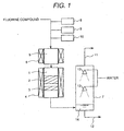
- the apparatus shown in Fig. 1 comprises a reactor 1, a pre-heater 5, a nitrogen gas supplying unit 8 for adding nitrogen gas to the fluorine compounds, an oxygen supplying unit 9 for adding oxygen or an oxygen-containing gas to the fluorine compounds, a pure water supplying unit 10 for adding pure water to the fluorine compounds, and a gas scrubbing tower 7 for scrubbing the gas stream flowing out from the reactor 1 with water.
- the pre-heater 5 has a heater 6, and the reactor 1 has a heater 4.
- the reactor 1 contains a first catalyst 2 and a second catalyst 3.
- the gas scrubbing tower 7 has spray nozzles 13 for spraying water.
- water 14 absorbing hydrogen fluoride and other water-soluble components accumulates at the bottom part of the gas scrubbing tower 7 and is then discharged to the outside of the gas scrubbing tower 7 through a drain pipe 12.
- the gas, from which hydrogen fluoride has been removed in the gas scrubbing tower 7, is discharged to the outside of the gas scrubbing tower 7 through a gas discharging pipe 11.
- a decomposition treatment of SF 6 was conducted by using an apparatus shown in Fig. 1 .
- An aluminum-nickel catalyst was used as first catalyst 2.
- the composition of the catalyst was such that the molar ratio Al/Ni was 80/20.
- the catalyst was prepared in the following manner. Commercially available boehmite powder was dried and calcinated at a temperature of 120°C for 1 hour. An aqueous solution obtained by dissolving 210.82 g of nickel nitrate hexahydrate was added to 200g of the powder, followed by mixing and kneading. Thereafter, the mixture was baked at a temperature of 250°C to 300°C for about 2 hours and calcinated at a temperature of 700°C for 2 hours. After calcination, pulverization and classification were conducted to obtain a particle diameter of 0.5 to 1 mm. A catalyst containing aluminum and nickel in the form of an oxide was thus obtained.
- a catalyst containing Pd and La carried on alumina was used as second catalyst 3.
- the preparation method of the second catalyst is as follows.
- Commercially available granular alumina having a particle diameter of from 2 to 4 mm (NKHD-24, produced by Sumitomo Chemical Industries, Ltd.) was impregnated with La 2 O 3 to such an extent that La 2 O 3 was contained in an amount of 10 wt% based on the weight of alumina.
- an aqueous solution obtained by dissolving 26.84 g of lanthanum nitrate hexahydrate in pure water was added to 100 g of alumina to conduct impregnation with La.
- the gas flowing out from the reactor 1 was supplied to the gas scrubbing tower 7 to absorb HF and other water-soluble components, such as SO 3 , in water.
- the SO 2 F 2 concentration of the exhaust gas flowing out from the gas scrubbing tower 7 was measured by TCD (thermal conductivity detector) gas chromatography.
- the SF 6 concentration of the gas was measured by TCD gas chromatography.
- the TCD gas chromatograph used had a detection limit for SO 2 F 2 of 5 ppm.
- SF 6 was treated with the first catalyst containing aluminum and nickel as an oxide, SF 6 conversion was obtained more then 80% and was substantially constant from the initial stage of the experiment to the time after 2000 hours.
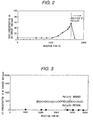
- Fig. 2 shows the relationship between the SO 2 F 2 concentration and the reaction time.
- the SO 2 F 2 concentration was lower than 5 ppm, the detection limit, from the initial stage of the experiment to the time after 1000 hours, but was quickly increased beyond 1000 hours, and 57 ppm were detected after 1600 hours.
- the experiment was further continued after charging the second catalyst 3.
- the SO 2 F 2 concentration was decreased to a level lower than 5 ppm. It has been confirmed from the foregoing that the Pd and La-carrying alumina catalyst is effective to decompose SO 2 F 2 in the presence of hydrogen fluoride.
- a mixed gas of CF 4 and CHF 3 was decomposed using the apparatus shown in Fig. 1 .
- a mixed gas of CF 4 and CHF 3 is often used as an etching gas for semiconductor manufacturing.
- the first catalyst 2 was the same as that used in Reference Example 1.
- the second catalyst 3 was the same as that used in Reference Example 1 except that commercially available granular alumina having a particle diameter of 2 to 4 mm (NKHD-24 produced by Sumitomo Chemical Industries, Ltd.) was pulverized to a diameter of 0.5 to 1 mm, followed by drying in the air at 120°C for 2 hours.
- the CF 4 concentration was 0.25 vol%
- the CHF 3 concentration was 0.25 vol%
- the O 2 concentration was 4 vol%
- the water vapor concentration was 25 vol%.
- the reaction temperature was 700°C.
- the experiment was conducted for two cases, i.e., only the first catalyst 2 was charged in the reactor 1, but the second catalyst 3 was not charged, and both the first catalyst 2 and the second catalyst 3 were charged in the reactor 1.
- the space velocity of the gas to be processed was 1000 h -1 at the first catalyst 2 and 10,000 h -1 at the second catalyst 3.
- the CO concentration of the exhaust gas flowing out from the gas scrubbing tower 7 was measured by TCD gas chromatography.
- the TCD gas chromatograph used had a detection limit for CO of 1 ppm.
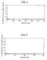
- Fig. 3 shows the relationship between the reaction time from the start of the experiment and the CO concentration.
- the CO concentration was as large as about 500 ppm when the treatment was conducted only with the aluminum-nickel catalyst, but the CO concentration could be decreased to a level that could not be detected by the TCD gas chromatograph by providing the Pd and La-carrying alumina catalyst.
- C 2 F 6 was decomposed by using the apparatus shown in Fig. 1 .
- the first catalyst 2 and the second catalyst 3 used were the same as those used in Reference Example 1.
- the C 2 F 6 concentration was 0.5 vol%
- the oxygen concentration was 4 vol%
- the water vapor concentration was 25 vol%.
- the reaction temperature was 750°C.
- the space velocity was the same as in Reference Example 1.
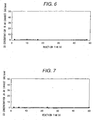
- the CO concentration in the exhaust gas flowing out from the gas scrubbing tower was constantly about 1 ppm from the initial stage of the treatment to the time after 600 hours.
- C 4 F 8 was decomposed by using the apparatus shown in Fig. 1 .
- the first catalyst 2 and the second catalyst 3 used were the same as those used in Reference Example 1.
- the C 4 F 8 concentration was 0.2 vol%
- the oxygen concentration was 4 vol%
- the water vapor concentration was 10 vol%.
- the reaction temperature was 800°C.
- the space velocity was the same as in Reference Example 1.
- the CO concentration in the exhaust gas flowing out from the gas scrubbing tower was constantly about 1 ppm from the initial stage of the treatment to the time after for 200 hours.
- C 3 F 8 was decomposed by using the apparatus shown in Fig. 1 .
- the first catalyst 2 and the second catalyst 3 used were the same as those used in Reference Example 1.
- the C 3 F 8 concentration was 0.2 vol%
- the oxygen concentration was 4 vol%
- the water vapor concentration was 10 vol%.
- the reaction temperature was 800°C.
- the space velocity was the same as in Reference Example 1.
- the CO concentration in the exhaust gas flowing out from the gas scrubbing tower was constantly about 1 ppm from the initial stage of the treatment to the time after lapsing for 48 hours.
- C 5 F 8 was decomposed by using the apparatus shown in Fig. 1 .
- the first catalyst 2 and the second catalyst 3 used were the same as those used in Reference Example 1.
- the C 5 F 8 concentration was 0.2 vol%
- the oxygen concentration was 4 vol%
- the water vapor concentration was 10 vol%.
- the reaction temperature was 800°C.
- the space velocity was the same as in Reference Example 1.
- the CO concentration in the exhaust gas flowing out from the gas scrubbing tower was constantly about 1 ppm from the initial stage of the treatment to the time after lapsing for 50 hours.
- a fluorine compounds containing C 4 F 8 was decomposed by using the apparatus shown in Fig. 1 while the material of the second catalyst 3 was changed.
- the first catalyst 2 was the same as that used in Reference Example 1.
- the C 4 F 8 concentration was 0.5 vol%
- the oxygen concentration was 4 vol%
- the water vapor concentration was 25 vol%.
- the reaction temperature was 700°C.
- the space velocity was 1000 h -1 at the fluorine compounds decomposition catalyst 2 and 3000 h -1 at the harmful component removing catalyst 3.
- a Pd and La-carrying alumina catalyst was prepared in the same manner as in Reference Example 2.
- La carried on alumina was prepared in the same manner as in the preparation of the Pd and La-carrying alumina in Reference Example 2.
- the resulting La-carrying alumina was impregnated with Pt in such a manner that Pt was contained in an amount of 0.5 wt%, based on the weight of the La-carrying alumina.
- 100 g of the La-carrying alumina were impregnated with a solution obtained by dissolving 11.08 g of a dinitrodiammine platinum nitric acid solution containing 4.514 wt% of Pt as a metal in pure water. Thereafter, it was dried at 120°C in the air for 2 hours and further calcinated at a temperature of 700°C in the air.
- a Pt and La-carrying alumina catalyst was obtained.
- the procedures for preparing La on alumina were the same as in Reference Example 2.
- the resulting La-carrying alumina was impregnated with Rh in such a manner that Rh was contained in an amount of 0.5 wt% of the weight of the La-carrying alumina. That is, 100 g of the La-carrying alumina were impregnated with a solution obtained by dissolving 11.31 g of a rhodium nitrate solution containing 4.422 wt% of Rh as a metal in pure water. Thereafter, it was dried at a temperature of 120°C in the air for 2 hours and further calcinated at a temperature of 700°C. As a result, a Rh and La-carrying alumina catalyst was obtained.
- the procedures for preparing La on alumina were the same as in Reference Example 2.
- the resulting La-carrying alumina was impregnated with Au in such a manner that Au was contained in an amount of 0.5 wt% of the weight of the La-carrying alumina. That is, 100 g of the La-carrying alumina were impregnated with a solution obtained by dissolving 10 g of chloroauric acid containing 50 g/l of gold as a metal in pure water. Thereafter, it was dried at a temperature of 120°C in the air for 2 hours and further calcinated at a temperature of 700°C. As a result, an Au and La-carrying alumina catalyst was obtained.
- the procedures for preparing La on alumina were the same as in Reference Example 2.
- the resulting La-carrying alumina was impregnated with Ir in such a manner that Ir was contained in an amount of 0.5 wt% of the weight of the La-carrying alumina. That is, 100 g of the La-carrying alumina were impregnated with a solution obtained by dissolving 10.74 g of a chloroiridic acid solution containing 4.656 wt% of Ir as a metal in pure water. Thereafter, it was dried at a temperature of 120°C in the air for 2 hours and further calcinated at a temperature of 700°C. As a result, an Ir and La-carrying alumina catalyst was obtained.
- granular alumina having a particle diameter of from 2 to 4 mm was pulverized to a diameter of 0.5 to 1 mm, and then dried in the air at 120°C for 2 hours. After drying, the alumina was impregnated with Pd in such a manner that Pd was contained in an amount of 0.5 wt% of the weight of the alumina. That is, 100 g of the alumina were impregnated with a solution obtained by dissolving 11.26 g of a palladium nitrate solution containing 4.439 wt% of Pd as a metal in pure water. Thereafter, it was dried at a temperature of 120°C in the air for 2 hours and further calcinated at a temperature of 700°C. As a result, a Pd-carrying alumina catalyst was obtained.
- granular alumina having a particle diameter of 2 to 4 mm (NKHD-24, produced by Sumitomo Chemical Industries, Ltd.) was pulverized to a diameter of from 0.5 to 1 mm, and then dried in the air at 120°C for 2 hours. After drying, the alumina was impregnated with Pt in such a manner that Pt was contained in an amount of 0.5 wt% of the weight of the alumina. That is, 100 g of the alumina were impregnated with a solution obtained by dissolving 11.08 g of a dinitrodiammine platinum nitric acid solution containing 4.514 wt% of Pt as a metal in pure water. Thereafter, it was dried at a temperature of 120°C in the air for 2 hours and further calcinated at a temperature of 700°C. As a result, a Pt-carrying alumina catalyst was obtained.
- granular alumina having a particle diameter of 2 to 4 mm (NKHD-24, produced by Sumitomo Chemical Industries, Ltd.) was pulverized to a diameter of from 0.5 to 1 mm, and then dried in the air at 120°C for 2 hours. After drying, the alumina was impregnated with Cu in such a manner that CuO was contained in an amount of 10 wt% of the weight of the alumina. That is, 100 g of the alumina were impregnated with an aqueous solution obtained by dissolving 30.4 g of copper nitrate trihydrate in pure water. Thereafter, it was dried at a temperature of 120°C in the air for 2 hours and further calcinated at a temperature of 700°C. As a result, a Cu-carrying alumina catalyst was obtained.
- granular alumina having a particle diameter of 2 to 4 mm (NKHD-24, produced by Sumitomo Chemical Industries, Ltd.) was pulverized to a diameter of from 0.5 to 1 mm, and then dried in the air at 120°C for 2 hours. After drying, the alumina was impregnated with Mn in such a manner that Mn 2 O 3 was contained in an amount of 10 wt% of the weight of the alumina. That is, 100 g of the alumina were impregnated with an aqueous solution obtained by dissolving 36.34 g of manganese nitrate hexahydrate in pure water. Thereafter, it was dried at a temperature of 120°C in the air for 2 hours and further calcinated at a temperature of 700°C. As a result, a Mn-carrying alumina catalyst was obtained.
- granular alumina having a particle diameter of 2 to 4 mm (NKHD-24, produced by Sumitomo Chemical Industries, Ltd.) was pulverized to a diameter of from 0.5 to 1 mm, and then dried in the air at 120°C for 2 hours. After drying, the alumina was impregnated with Fe in such a manner that Fe 2 O 3 was contained in an amount of 10 wt% of the weight of the alumina. That is, 100 g of the alumina were impregnated with an aqueous solution obtained by dissolving 50.59 g of iron nitrate nonahydrate in pure water. Thereafter, it was dried at a temperature of 120°C in the air for 2 hours and further calcinated at a temperature of 700°C. As a result, a Fe-carrying alumina catalyst was obtained.
- granular titania (CS-224, produced by Sakai Chemical Industry Co., Ltd.) was pulverized and classified to obtain particles having a diameter of 0.5 to 1 mm, and then heated to 120°C for 2 hours. 100 g of the resulting titania were impregnated with a hydrogen peroxide solution containing 82.2 g of ammonium paratungstate dissolved therein, and then again heated to 120°C for 2 hours and to 500°C for further 2 hours. 100 g of the resulting tungsten-carried titania were impregnated with a solution obtained by dissolving 11.26 g of a palladium nitrate solution containing 4.439 wt% of Pd as a metal. Thereafter, it was dried at a temperature of 120°C in the air for 2 hours and further calcinated at a temperature of 700°C. The amount of tungsten as WO 3 was 71.9 wt% of the titania.
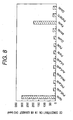
- Fig. 8 is a graph showing the CO concentration after lapsing 1 hour from the start of the experiment in the case where the treatment is conducted by using only the first containing aluminum and nickel as an oxide (the bar on the extreme left) and the cases where the treatment is conducted by using both the first catalyst and the second catalyst.
- the measurement of the CO concentration was conducted by TCD gas chromatography.
- a decomposition treatment of fluorine compounds containing C 2 F 6 was conducted by using the apparatus shown in Fig. 1 , comprising an Al-Zn catalyst containing aluminum and zinc as an oxide and a mixed oxide as the first catalyst 2 and a Pd and La-carrying alumina catalyst as the second catalyst 3. The experiment was also conducted for the case where the second catalyst 3 was not used.
- the material, the composition and the preparation method of the second catalyst 3 were the same as in Reference Example 2.
- the C 2 F 6 concentration was 0.5 vol%
- the oxygen concentration was 4 vol%
- the water vapor concentration was 25 vol% at the inlet of the reactor 1.
- the reaction temperature was 750°C.
- the other conditions are the same as in Reference Example 1.
- the Al-Zn catalyst was prepared in the following manner. Commercially available boehmite powder was dried and calcinated at a temperature of 120°C for 1 hour. An aqueous solution obtained by dissolving 96.39 g of zinc nitrate hexahydrate was added to 126.65 g of the powder, followed by mixing and kneading. Thereafter, the mixture was dried at a temperature of 250 to 300°C for 2 hours and at a temperature of 700°C for 2 hours. After baking, pulverization and classification were conducted to obtain a particle diameter of 0.5 to 1 mm. A catalyst containing 85 mol% of Al and 15 mol% of Zn was thus obtained.
- the CO concentration of the gas flowing out from the gas scrubbing tower after lapsing one hour from the start of the treatment was about 350 ppm when the treatment was conducted by using only the Al-Zn catalyst, but was improved to 1 ppm when the Pd and La-carrying alumina catalyst was also used.
- a decomposition treatment of fluorine compounds containing C 2 F 6 was conducted by using the apparatus shown in Fig. 1 , comprising an Al-Ti catalyst containing aluminum and titanium as an oxide as the first catalyst 2 and a Pd and La-carrying alumina catalyst as the second catalyst 3.
- the experiment was conducted for both the cases where the second catalyst 3 was used and was not used.
- the material, the composition and the preparation method of the second catalyst 3 were the same as in Reference Example 8.
- the conditions, such as concentrations of the gas to be processed and the reaction temperature at the inlet of the reactor 1, were the same as in Reference Example 8.
- the Al-Ti catalyst was prepared in the following manner. Commercially available boehmite powder was dried and calcinated at a temperature of 120°C for 1 hour.
- the CO concentration of the gas flowing out from the gas scrubbing tower after lapsing one hour from the start of the treatment was about 320 ppm when the treatment was conducted by using only the Al-Ti catalyst, but was improved to 1 ppm when the Pd and La-carrying alumina catalyst was also used.
- Fig. 9 is a schematic diagram showing an example, in which the apparatus for the decomposition of fluorine compounds according to the invention is provided on a semiconductor etching line.
- a gas comprising fluorine compounds such as SF 6 and mixed CF 4 and CHF 3 is introduced into an etching chamber of reduced pressure to excite a plasma which is allowed to react with a semiconductor wafer. Thereafter, the gas inside the etching chamber is sucked by a vacuum pump, at which the concentration of the fluorine compounds becomes about 0.5 to 5 vol% since nitrogen gas is flushed for protection of the pump.
- the apparatus for the decomposition of fluorine compounds according to the invention has a pre-treatment tower 99 for scrubbing the gas discharged from the etching chamber. Water soluble components contained in the gas are removed in the pre-treatment tower 99.
- the gas having been treated in the pre-treatment tower 99 is fed to a pre-heater 5 for heating.
- Water 20 is also fed to the pre-heater 5. It is preferred that the water 20 is fed to the pre-heater after removing impurities, such as calcium, contained in the water by passing through an ion exchange resin 16.
- the concentration of the fluorine compounds is adjusted to a range of about 0.1 to 5 vol% at the pre-heater 5.
- the amount of water is adjusted to a range of about 5 to 75 times the molar number of the fluorine compounds.
- the amount of the air is adjusted to make the oxygen concentration be a range of about from 0.2 to 15 vol%.
- the gas to be processed having the concentrations thus adjusted is heated to a temperature of 650 to 850°C by using a heater 6, such as an electric furnace, and supplied to a reactor 1.
- a first catalyst 2 and a second catalyst 3 are charged in the reactor 1. It is preferred that the reactor 1 is also heated to a temperature of about from 650 to 850°C by a heater 4, such as an electric furnace.
- the gas to be treated supplied to the rector 1 is firstly brought into contact with the first catalyst 2, whereby the fluorine compounds react with water to decompose the fluorine compounds to hydrogen fluoride and carbon monoxide or SO 2 F 2 . Thereafter, the gas is brought into contact with the second catalyst 3, whereby carbon monoxide, carbon dioxide, SO 3 and SO 2 F 2 are decomposed.
- the gas emitted from the reactor 1 is supplied to a cooling chamber 17 to cool, for example, by spraying water.
- the gas emitted from the cooling chamber 17 is supplied to a gas scrubbing tower 7 for scrubbing with water sprayed from a spray nozzle 13, whereby hydrogen fluoride and other water soluble components are removed.
- a filler 19 formed from plastic particles is filled in the gas scrubbing tower 7 to ensure contact of the gas with water.
- the water absorbing hydrogen fluoride and other water soluble components in the gas scrubbing tower 7 is discharged from the gas scrubbing tower 7 by sucking with a pump 21, followed by treating, for example, in a waste water treatment apparatus.
- the gas, from which hydrogen fluoride and other water soluble components are removed in the gas scrubbing tower 7, is discharged from the gas scrubbing tower 7 by sucking with a blower 22.
- the point of the apparatus shown in Fig. 9 is that the air 15 is added to the gas supplied to the second catalyst 3 in the reactor 1.
- the fluorine compounds are decomposed, and CO or SO 2 F 2 formed by the decomposition of the fluorine compounds can also be removed.
Landscapes
- Chemical & Material Sciences (AREA)
- Engineering & Computer Science (AREA)
- Chemical Kinetics & Catalysis (AREA)
- Materials Engineering (AREA)
- Organic Chemistry (AREA)
- Environmental & Geological Engineering (AREA)
- Health & Medical Sciences (AREA)
- Biomedical Technology (AREA)
- Analytical Chemistry (AREA)
- General Chemical & Material Sciences (AREA)
- Oil, Petroleum & Natural Gas (AREA)
- Exhaust Gas Treatment By Means Of Catalyst (AREA)
- Catalysts (AREA)
Claims (9)
- Verfahren zur Zersetzung von Fluorverbindungen, wie PFCs (perfluorierten Kohlenwasserstoffen), HFCs (partiell fluorierten Kohlenwasserstoffen), SF6 und NF3, das folgende Stufen umfasst:(A) Einführen von Wasserdampf und eines zur Verdünnung dienenden inerten Gases in die Fluorverbindungen,(B) Inkontaktbringen des Gasgemisches mit einem ersten Katalysator (2) zur Zersetzung der Fluorverbindungen,(C) Inkontaktbringen des aus (B) resultierenden Gases mit einem zweiten Katalysator (3) zur Zersetzung schädlicher Substanzen wie CO, N2O und SO2F2
und(D) Gaswäsche des aus (C) resultierenden Gases mit Wasser oder einer alkalischen wässerigen Lösung zur Entfernung von Fluorwasserstoff und anderen wasserlöslichen Bestandteilen, die im Gas enthalten sind,wobei- Sauerstoff oder ein Sauerstoff enthaltendes Gas in das aus Stufe (B) resultierende und in Stufe (C) strömende Gas eingeführt wird,- der erste Katalysator (2) zur Zersetzung der Fluorverbindungen Al-Ni-Oxid, Al-Zn-Oxid oder Al-Ti-Oxid ist,- der zweite Katalysator (3) zur Zersetzung der schädlichen Substanzen einen Träger aufweist, der unter Aluminiumoxid, Titanoxid und Zirkoniumoxid ausgewählt ist und mindestens eines der Metalle Pd, Pt, Cu, Mn, Fe, Co, Rh, Ir und Au in Form eines Metalls oder in Form eines Oxids enthält oder bei dem es sich um mit Wolframoxid beschichtetes Titanoxid handelt,
und- der erste Katalysator (2) und der zweite Katalysator (3) durch eine gemeinsame Heizeinrichtung (4) auf der gleichen Reaktionstemperatur gehalten werden. - Verfahren nach Anspruch 1, dadurch gekennzeichnet, dass die Reaktionstemperatur des ersten Katalysators (2) und des zweiten Katalysators (3) im Bereich von 650 bis 850 °C gehalten wird.
- Verfahren nach Anspruch 1 oder 2, dadurch gekennzeichnet, dass der zweite Katalysator (3) ferner mindesten ein Oxid enthält, das unter La-Oxid und Ba-Oxid ausgewählt ist.
- Verfahren nach einem oder mehreren der Ansprüche 1 bis 3, dadurch gekennzeichnet, dass der zweite Katalysator (3) ausgewählt ist unter Pd und La auf Aluminiumoxid, Pt und La auf Aluminiumoxid, Rh und La auf Aluminiumoxid, Au und La auf Aluminiumoxid, Ir und La auf Aluminiumoxid, Pd auf Aluminiumoxid, Pt auf Aluminiumoxid, Cu auf Aluminiumoxid, Mn auf Aluminiumoxid, Pd und W auf Titanoxid sowie Co auf Aluminiumoxid.
- Verfahren nach Anspruch 4, dadurch gekennzeichnet, dass der zweite Katalysator (3) aus Pd und La (La2O3) auf Aluminiumoxid besteht.
- Vorrichtung zur Zersetzung von Fluorverbindungen, wie PFCs (perfluorierten Kohlenwasserstoffen), HFCs (partiell fluorierten Kohlenwasserstoffen), SF6 und NF3, die aufweist:- einen Reaktor (1), der verbunden ist mit der Quelle für die Fluorverbindungen, einer Inertgas-Versorgungseinheit, einer Wasserdampf-Versorgungseinheit (20) und einer Sauerstoff-Versorgungseinheit (15) zum Einführen von Sauerstoff oder eines Sauerstoff enthaltenden Gases und einen ersten Katalysator (2) zur Zersetzung der Fluorverbindungen und einen zweiten Katalysator (3) zur Zersetzung von schädlichen Substanzen, wie CO, N2O und SO2F2 aufweist, die darin eingebracht sind, wobei der erste Katalysator (2) stromauf vom zweiten Katalysators (3) vorgesehen ist, und der eine Heizeinrichtung (4) zur Beheizung des ersten Katalysators (2) aufweist,
und- einen Gaswaschturm (7), der mit dem Reaktor (1) verbunden ist und Sprühdüsen (13) zum Inkontaktbringen des aus dem Reaktor (1) abgeführten Gases mit Wasser oder einer alkalischen wässerigen Lösung zur Entfernung von Fluorwasserstoff und anderen wasserlöslichen Verbindungen aus dem Gas aufweist,wobei- die Sauerstoff-Versorgungseinheit (15) stromauf vom zweiten Katalysator (3) und stromab vom ersten Katalysator (2) vorgesehen ist,- der erste Katalysator (2) aus Al-Ni-Oxid, Al-Zn-Oxid oder Al-Ti-Oxid besteht,- der zweite Katalysator (3) einen Träger aufweist, der unter Aluminiumoxid, Titanoxid und Zirkoniumoxid ausgewählt ist und mindestens eines der Metalle Pd, Pt, Cu, Mn, Fe, Co, Rh, Ir und Au in Form eines Metalls oder in Form eines Oxids enthält oder bei dem es sich um mit Wolframoxid beschichtetes Titanoxid handelt,
und- die Heizeinrichtung (4) dem ersten Katalysator (2) und dem zweiten Katalysator (3) gemeinsam ist und so ausgebildet ist, dass sie den ersten Katalysator (2) und den zweiten Katalysator auf der gleichen Temperatur hält. - Vorrichtung nach Anspruch 6, dadurch gekennzeichnet, dass der zweite Katalysator (3) ausgewählt ist unter Pd und La auf Aluminiumoxid, Pt und La auf Aluminiumoxid, Rh und La auf Aluminiumoxid, Au und La auf Aluminiumoxid, Ir und La auf Aluminiumoxid, Pd auf Aluminiumoxid, Pt auf Aluminiumoxid, Cu auf Aluminiumoxid, Mn auf Aluminiumoxid, Pd und W auf Titanoxid sowie Co auf Aluminiumoxid.
- Vorrichtung nach Anspruch 6 oder 7, dadurch gekennzeichnet, dass der zweite Katalysator (3) aus Pd und La (La2O3) auf Aluminiumoxid besteht.
- Vorrichtung nach einem oder mehreren der Ansprüche 6 bis 8, dadurch gekennzeichnet, dass stromauf vom Reaktor (1) eine Vorheizeinrichtung (5) vorgesehen ist.
Applications Claiming Priority (1)
| Application Number | Priority Date | Filing Date | Title |
|---|---|---|---|
| PCT/JP1999/003074 WO2000074821A1 (fr) | 1999-06-09 | 1999-06-09 | Procede et systeme pour eliminer un compose fluore par decomposition |
Publications (3)
| Publication Number | Publication Date |
|---|---|
| EP1205234A1 EP1205234A1 (de) | 2002-05-15 |
| EP1205234A4 EP1205234A4 (de) | 2003-04-16 |
| EP1205234B1 true EP1205234B1 (de) | 2010-03-17 |
Family
ID=14235919
Family Applications (1)
| Application Number | Title | Priority Date | Filing Date |
|---|---|---|---|
| EP99923975A Expired - Lifetime EP1205234B1 (de) | 1999-06-09 | 1999-06-09 | Verfahren und vorrichtung zum entfernen von fluorhaltigen verbindungen durch zersetzung |
Country Status (7)
| Country | Link |
|---|---|
| US (1) | US7294315B1 (de) |
| EP (1) | EP1205234B1 (de) |
| JP (1) | JP4483154B2 (de) |
| KR (1) | KR100450853B1 (de) |
| DE (1) | DE69942158D1 (de) |
| TW (1) | TWI242462B (de) |
| WO (1) | WO2000074821A1 (de) |
Families Citing this family (22)
| Publication number | Priority date | Publication date | Assignee | Title |
|---|---|---|---|---|
| JP4065672B2 (ja) * | 2001-10-10 | 2008-03-26 | 株式会社荏原製作所 | フッ素含有化合物を含む排ガスの処理方法及び装置 |
| JP4214717B2 (ja) * | 2002-05-31 | 2009-01-28 | 株式会社日立製作所 | 過弗化物処理装置 |
| GB0418125D0 (en) * | 2004-08-13 | 2004-09-15 | Boc Group Plc | Treatment of effluent gases |
| US8043574B1 (en) | 2011-04-12 | 2011-10-25 | Midwest Refrigerants, Llc | Apparatus for the synthesis of anhydrous hydrogen halide and anhydrous carbon dioxide |
| US8128902B2 (en) * | 2011-04-12 | 2012-03-06 | Midwest Refrigerants, Llc | Method for the synthesis of anhydrous hydrogen halide and anhydrous carbon dioxide |
| KR101297604B1 (ko) * | 2011-05-03 | 2013-08-19 | 제주대학교 산학협력단 | 유전체 배리어 방전 활성화 알루미나를 이용한 육불화황 분해장치 및 분해방법 |
| US8834830B2 (en) | 2012-09-07 | 2014-09-16 | Midwest Inorganics LLC | Method for the preparation of anhydrous hydrogen halides, inorganic substances and/or inorganic hydrides by using as reactants inorganic halides and reducing agents |
| US10375901B2 (en) | 2014-12-09 | 2019-08-13 | Mtd Products Inc | Blower/vacuum |
| KR101949478B1 (ko) * | 2016-11-07 | 2019-02-18 | 전남대학교산학협력단 | 촉매 연소를 이용한 과불화 화합물 처리 장치 및 그 방법 |
| KR20180068590A (ko) | 2016-12-14 | 2018-06-22 | 한림대학교 산학협력단 | HFCs 분해 처리 방법 |
| KR101939609B1 (ko) * | 2016-12-23 | 2019-01-18 | 주식회사 에코프로 | 과불화화합물 분해 장치 및 분해 방법 |
| KR102041555B1 (ko) * | 2017-10-27 | 2019-11-06 | (주)명성씨.엠.아이 | 반도체 제조 공정에서 배출되는 유해가스 통합 처리시스템 |
| KR102081820B1 (ko) | 2019-09-17 | 2020-02-26 | 박태영 | HFCs 분해 처리 방법 |
| KR102081819B1 (ko) | 2019-09-17 | 2020-02-26 | 박태영 | HFCs 분해 처리 방법 |
| KR102235570B1 (ko) | 2020-02-19 | 2021-04-01 | 한국남동발전 주식회사 | 2가 마그네슘 이온이 담지된 산화알루미늄을 이용한 HFCs를 분해처리 방법 |
| KR102235569B1 (ko) | 2020-02-19 | 2021-04-01 | 한국남동발전 주식회사 | 촉매층에 흡착제가 포함된 HFCs 분해 처리 방법 |
| CN113155913B (zh) * | 2021-04-21 | 2022-07-08 | 浙江大学 | 用于检测六氟化硫分解产物的气敏传感器及其制备方法 |
| KR102569714B1 (ko) | 2021-06-25 | 2023-08-23 | 한림대학교 산학협력단 | 고유한 표면 특성을 가지는 수소불화탄소 분해용 촉매 및 이의 제조 방법 |
| CN113480390A (zh) * | 2021-07-20 | 2021-10-08 | 北京理工大学 | 一种氟聚物型安全环保开爆药及其制备方法 |
| US11827521B2 (en) | 2021-12-14 | 2023-11-28 | Industrial Technology Research Institute | Method for selectively chemically reducing CO2 to form CO |
| CN118304757B (zh) * | 2024-03-11 | 2025-06-10 | 武汉大学 | 一种基于双金属协同催化的废弃sf6高效热降解方法 |
| CN119680381B (zh) * | 2025-01-23 | 2025-12-19 | 武汉理工大学 | 一种光催化和电化学耦合六氟化硫降解装置 |
Family Cites Families (18)
| Publication number | Priority date | Publication date | Assignee | Title |
|---|---|---|---|---|
| JPS5149190A (en) | 1974-10-25 | 1976-04-28 | Nippon Catalytic Chem Ind | Kairyo sareta haikigasujokayoshokubai |
| JPS5226390A (en) * | 1975-08-26 | 1977-02-26 | Toyota Motor Corp | Oxidation catalyst used for the purification of exhaust gas |
| ZA837689B (en) | 1982-10-18 | 1984-06-27 | Universal Matthey Prod | Oxidation catalysts |
| JPS613040A (ja) * | 1984-06-16 | 1986-01-09 | Nissin Electric Co Ltd | ガスセンサ |
| DE3841847C1 (de) * | 1988-12-13 | 1990-02-01 | Man Technologie Ag, 8000 Muenchen, De | |
| DE3940493A1 (de) | 1989-12-07 | 1991-06-13 | Man Technologie Gmbh | Verfahren und vorrichtung zur entfernung von fluor und anorganischen fluoriden aus gasen |
| JPH04122419A (ja) | 1990-09-13 | 1992-04-22 | Toshiba Corp | 有機ハロゲン化物の分解処理方法及び分解触媒 |
| JPH0671529B2 (ja) | 1991-03-19 | 1994-09-14 | 荏原インフィルコ株式会社 | Cvd排ガス処理方法および装置 |
| JPH05220346A (ja) | 1991-12-18 | 1993-08-31 | Toshiba Corp | 有機系ハロゲン化合物の分解方法 |
| JPH0857255A (ja) | 1994-08-23 | 1996-03-05 | Hitachi Ltd | フロン分解システム |
| GB2295101B (en) | 1994-11-09 | 1998-03-25 | Cjb Developments Ltd | Process for the removal of halogenated organic compounds from air streams |
| US5759504A (en) * | 1994-12-28 | 1998-06-02 | Hitachi, Ltd. | Method for treating organohalogen compounds with catalyst |
| JPH08238418A (ja) * | 1995-03-06 | 1996-09-17 | Hitachi Ltd | 有機ハロゲン化合物の分解処理方法 |
| JP3977887B2 (ja) | 1997-01-14 | 2007-09-19 | 株式会社日立製作所 | フッ素化合物含有ガスの処理方法 |
| JPH10286439A (ja) | 1997-04-15 | 1998-10-27 | Ube Ind Ltd | 含フッ素化合物の分解法 |
| JP3269456B2 (ja) * | 1997-06-20 | 2002-03-25 | 株式会社日立製作所 | フッ素含有化合物の分解処理方法、触媒及び分解処理装置 |
| DE69820926T2 (de) * | 1997-06-20 | 2004-09-02 | Hitachi, Ltd. | Verfahren, Vorrichtung und Verwendung eines Katalysators zur Zersetzung fluorierter Verbindungen |
| JPH11123331A (ja) | 1997-08-22 | 1999-05-11 | Nissan Motor Co Ltd | 排気ガス浄化用触媒 |
-
1999
- 1999-06-09 EP EP99923975A patent/EP1205234B1/de not_active Expired - Lifetime
- 1999-06-09 KR KR10-2001-7011666A patent/KR100450853B1/ko not_active Expired - Fee Related
- 1999-06-09 WO PCT/JP1999/003074 patent/WO2000074821A1/ja not_active Ceased
- 1999-06-09 JP JP2001501349A patent/JP4483154B2/ja not_active Expired - Fee Related
- 1999-06-09 DE DE69942158T patent/DE69942158D1/de not_active Expired - Lifetime
- 1999-06-09 US US09/936,426 patent/US7294315B1/en not_active Expired - Fee Related
-
2000
- 2000-05-02 TW TW089108295A patent/TWI242462B/zh not_active IP Right Cessation
Also Published As
| Publication number | Publication date |
|---|---|
| EP1205234A1 (de) | 2002-05-15 |
| TWI242462B (en) | 2005-11-01 |
| EP1205234A4 (de) | 2003-04-16 |
| KR20020000152A (ko) | 2002-01-04 |
| DE69942158D1 (de) | 2010-04-29 |
| US7294315B1 (en) | 2007-11-13 |
| WO2000074821A1 (fr) | 2000-12-14 |
| JP4483154B2 (ja) | 2010-06-16 |
| KR100450853B1 (ko) | 2004-10-02 |
Similar Documents
| Publication | Publication Date | Title |
|---|---|---|
| EP1205234B1 (de) | Verfahren und vorrichtung zum entfernen von fluorhaltigen verbindungen durch zersetzung | |
| US6855305B2 (en) | Process for treating fluorine compound-containing gas | |
| JPWO2000074821A1 (ja) | フッ素化合物の分解処理方法及び分解処理装置 | |
| EP1103297B1 (de) | Verfahren und Vorrichtung zur Behandlung von Perfluorverbindungen enthaltenden Gasen | |
| EP1340533A1 (de) | Verfahren, Katalysator und Vorrichtung zur Zersetzung fluorierter Verbindungen | |
| US7261868B2 (en) | Process and apparatus for the decomposition of fluorine compounds | |
| US20090022642A1 (en) | Treatment method for decomposing perfluorocompound, decomposing catalyst and treatment apparatus | |
| US6676913B2 (en) | Catalyst composition and method of controlling PFC and HFC emissions | |
| JP2001190959A (ja) | フッ素化合物の分解用反応剤、分解方法及びその用途 | |
| CN116635132A (zh) | 氯气分解用催化剂、排出气体处理装置和氯气的分解方法 | |
| JP2007054714A (ja) | 亜酸化窒素の分解触媒及びその触媒を用いた亜酸化窒素の分解方法 | |
| JP4394555B2 (ja) | フッ素化合物含有ガスの処理方法及び処理装置 | |
| JP3376789B2 (ja) | 有機ハロゲン化合物の触媒による処理方法 | |
| WO2001021304A1 (en) | Alumina-based catalyst composition and method of destruction of pfc and hfc | |
| JP2009078237A (ja) | 半導体,液晶製造装置からの排出ガス処理方法 | |
| JP2023072888A (ja) | 亜酸化窒素分解用触媒の再生方法および亜酸化窒素の分解方法 | |
| JP4228870B2 (ja) | 触媒式pfc分解処理方法及び装置 | |
| EP2399662A1 (de) | Pyrolyseverfahren, Katalysatoren und Vorrichtungen zur Behandlung und/oder Detektion von verunreinigten Gasen | |
| JP3357255B2 (ja) | フロン分解触媒 | |
| JP2006314905A (ja) | フッ素化合物含有ガスの処理方法及び処理装置 | |
| JP2008100229A (ja) | フッ素化合物含有ガスの処理方法 |
Legal Events
| Date | Code | Title | Description |
|---|---|---|---|
| PUAI | Public reference made under article 153(3) epc to a published international application that has entered the european phase |
Free format text: ORIGINAL CODE: 0009012 |
|
| 17P | Request for examination filed |
Effective date: 20011227 |
|
| AK | Designated contracting states |
Kind code of ref document: A1 Designated state(s): DE FR NL |
|
| A4 | Supplementary search report drawn up and despatched |
Effective date: 20030303 |
|
| 17Q | First examination report despatched |
Effective date: 20050304 |
|
| GRAP | Despatch of communication of intention to grant a patent |
Free format text: ORIGINAL CODE: EPIDOSNIGR1 |
|
| GRAS | Grant fee paid |
Free format text: ORIGINAL CODE: EPIDOSNIGR3 |
|
| RAP1 | Party data changed (applicant data changed or rights of an application transferred) |
Owner name: HITACHI, LTD. |
|
| GRAA | (expected) grant |
Free format text: ORIGINAL CODE: 0009210 |
|
| AK | Designated contracting states |
Kind code of ref document: B1 Designated state(s): DE FR NL |
|
| REG | Reference to a national code |
Ref country code: NL Ref legal event code: T3 |
|
| REF | Corresponds to: |
Ref document number: 69942158 Country of ref document: DE Date of ref document: 20100429 Kind code of ref document: P |
|
| PLBE | No opposition filed within time limit |
Free format text: ORIGINAL CODE: 0009261 |
|
| STAA | Information on the status of an ep patent application or granted ep patent |
Free format text: STATUS: NO OPPOSITION FILED WITHIN TIME LIMIT |
|
| 26N | No opposition filed |
Effective date: 20101220 |
|
| PGFP | Annual fee paid to national office [announced via postgrant information from national office to epo] |
Ref country code: FR Payment date: 20110621 Year of fee payment: 13 |
|
| PGFP | Annual fee paid to national office [announced via postgrant information from national office to epo] |
Ref country code: NL Payment date: 20110629 Year of fee payment: 13 |
|
| PGFP | Annual fee paid to national office [announced via postgrant information from national office to epo] |
Ref country code: DE Payment date: 20110601 Year of fee payment: 13 |
|
| REG | Reference to a national code |
Ref country code: NL Ref legal event code: V1 Effective date: 20130101 |
|
| REG | Reference to a national code |
Ref country code: FR Ref legal event code: ST Effective date: 20130228 |
|
| PG25 | Lapsed in a contracting state [announced via postgrant information from national office to epo] |
Ref country code: FR Free format text: LAPSE BECAUSE OF NON-PAYMENT OF DUE FEES Effective date: 20120702 Ref country code: DE Free format text: LAPSE BECAUSE OF NON-PAYMENT OF DUE FEES Effective date: 20130101 Ref country code: NL Free format text: LAPSE BECAUSE OF NON-PAYMENT OF DUE FEES Effective date: 20130101 |
|
| REG | Reference to a national code |
Ref country code: DE Ref legal event code: R119 Ref document number: 69942158 Country of ref document: DE Effective date: 20130101 |