EP1205295A1 - Arthroskopischer Simulator einer Gelenkhülle - Google Patents
Arthroskopischer Simulator einer Gelenkhülle Download PDFInfo
- Publication number
- EP1205295A1 EP1205295A1 EP00490048A EP00490048A EP1205295A1 EP 1205295 A1 EP1205295 A1 EP 1205295A1 EP 00490048 A EP00490048 A EP 00490048A EP 00490048 A EP00490048 A EP 00490048A EP 1205295 A1 EP1205295 A1 EP 1205295A1
- Authority
- EP
- European Patent Office
- Prior art keywords
- cavity
- simplified
- simulator according
- model
- shoulder
- Prior art date
- Legal status (The legal status is an assumption and is not a legal conclusion. Google has not performed a legal analysis and makes no representation as to the accuracy of the status listed.)
- Withdrawn
Links
Images


Classifications
-
- G—PHYSICS
- G09—EDUCATION; CRYPTOGRAPHY; DISPLAY; ADVERTISING; SEALS
- G09B—EDUCATIONAL OR DEMONSTRATION APPLIANCES; APPLIANCES FOR TEACHING, OR COMMUNICATING WITH, THE BLIND, DEAF OR MUTE; MODELS; PLANETARIA; GLOBES; MAPS; DIAGRAMS
- G09B23/00—Models for scientific, medical, or mathematical purposes, e.g. full-sized devices for demonstration purposes
- G09B23/28—Models for scientific, medical, or mathematical purposes, e.g. full-sized devices for demonstration purposes for medicine
- G09B23/285—Models for scientific, medical, or mathematical purposes, e.g. full-sized devices for demonstration purposes for medicine for injections, endoscopy, bronchoscopy, sigmoidscopy, insertion of contraceptive devices or enemas
-
- B—PERFORMING OPERATIONS; TRANSPORTING
- B29—WORKING OF PLASTICS; WORKING OF SUBSTANCES IN A PLASTIC STATE IN GENERAL
- B29C—SHAPING OR JOINING OF PLASTICS; SHAPING OF MATERIAL IN A PLASTIC STATE, NOT OTHERWISE PROVIDED FOR; AFTER-TREATMENT OF THE SHAPED PRODUCTS, e.g. REPAIRING
- B29C64/00—Additive manufacturing, i.e. manufacturing of three-dimensional [3D] objects by additive deposition, additive agglomeration or additive layering, e.g. by 3D printing, stereolithography or selective laser sintering
- B29C64/10—Processes of additive manufacturing
- B29C64/106—Processes of additive manufacturing using only liquids or viscous materials, e.g. depositing a continuous bead of viscous material
- B29C64/124—Processes of additive manufacturing using only liquids or viscous materials, e.g. depositing a continuous bead of viscous material using layers of liquid which are selectively solidified
- B29C64/129—Processes of additive manufacturing using only liquids or viscous materials, e.g. depositing a continuous bead of viscous material using layers of liquid which are selectively solidified characterised by the energy source therefor, e.g. by global irradiation combined with a mask
- B29C64/135—Processes of additive manufacturing using only liquids or viscous materials, e.g. depositing a continuous bead of viscous material using layers of liquid which are selectively solidified characterised by the energy source therefor, e.g. by global irradiation combined with a mask the energy source being concentrated, e.g. scanning lasers or focused light sources
-
- B—PERFORMING OPERATIONS; TRANSPORTING
- B29—WORKING OF PLASTICS; WORKING OF SUBSTANCES IN A PLASTIC STATE IN GENERAL
- B29L—INDEXING SCHEME ASSOCIATED WITH SUBCLASS B29C, RELATING TO PARTICULAR ARTICLES
- B29L2031/00—Other particular articles
- B29L2031/753—Medical equipment; Accessories therefor
- B29L2031/7532—Artificial members, protheses
Definitions
- the present invention relates to the field of gesture simulation medical devices, and relates to an arthroscopy simulator of a cavity articular. It finds more particularly its application to learning the gestures required to perform an arthroscopy of a joint cavity, such as for example the joint cavity of the shoulder.
- arthroscopy The technical mastery of arthroscopy by the surgeon requires initial learning, as well as maintaining competence surgeon, which can only be obtained by repeating the gesture. Unlike, for example, digestive endoscopy or Gynecological, arthroscopy does not lend itself well to learning about animals. Learning from a human cadaver requires logistics important, material dedicated to this use, specific premises. he also poses the problem of the number of corpses available and their conservation with all the costs that this generates.
- arthroscopy simulators in particular of the knee, which use artificial devices (arthroscope and hook) and which are designed to automatically replenish and real-time three-dimensional image of the joint cavity, from MRI (Magnetic Resonance Imaging) or CT slices real articulation, and depending on the position and orientation of the dummy arthroscope.
- MRI Magnetic Resonance Imaging
- CT slices real articulation
- One of the aims of the present invention is to provide a arthroscopy simulator of a joint cavity which allows to obtain a very good tactile rendering, mainly in the event of a collision with a wall bone, in line with the simulated images of the cavity, and which is simpler in design than prior art 3D simulators with motorized force feedback systems.
- the simulator of the invention which in known manner comprises at least one dummy instrument simulating materially an arthroscope and a graphic reconstruction system of images designed to display an image in real time on a screen three-dimensional simulated joint cavity as a function of position and the orientation of the instrument.
- the simulator is designed on the basis of a simplified three-dimensional geometric model made up of the main anatomical elements of the joint cavity and their assembly;
- the graphic system of image reconstruction uses at least one three-dimensional graphic model made from simplified three-dimensional geometric model;
- the simulator includes a mechanical model which consists of an assembly of parts which physically reproduce the three-dimensional geometric model simplified.
- the implementation of a simplified three-dimensional geometric model not including all anatomical details of the joint cavity simplifies calculations and the real-time display of the simulated cavity.
- the model mechanical and the graphic model being the replica of the same model simplified three-dimensional geometric of the articular cavity, we obtain easily a good match between image and tactile sensation induced by the contact of the operating instrument with the parts of the model mechanical. Also, this concordance makes it possible to save a collision detection of an operating instrument with a wall bone, and thereby save computing time.
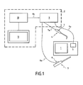
- an arthroscopy simulator of the invention comprises a mannequin 1 which essentially comprises a assembly of mechanical parts, physically reproducing and simplified way an articular cavity, this part assembly constituting the simplified mechanical model of the invention.
- the simulated joint cavity is a shoulder cavity, being clarified that the invention is not limited to this particular application, but can also be applied to the simulation of any other cavity joint, and for example to the knee joint cavity.
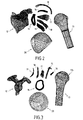
- An example of a simplified mechanical model of an articular cavity of the shoulder will be described below in detail with reference to the figures 2 to 5.
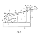
- An exemplary embodiment of a mannequin 1 made from this simplified mechanical model will be described later so detailed with reference to Figure 6.
- the simulator in Figure 1 also includes a system graph 2 for real-time calculation and reconstruction of 3D images of the joint cavity, as well as two operating instruments consisting of a dummy arthroscope 3 and a feeler hook 4.
- the graphical system 2 of calculation and real-time reconstruction of 3D images includes a module 9 for acquiring the instant position and orientation of the arthroscope 3 and the probe hook 4, a generator 10 of 3D images, and a screen 11 for displaying the images calculated by the generator 10.
- the dummy arthroscope 3 is equipped with a sensor making it possible to detect its position in a 3D reference frame (along the X, Y, Z axes), and its orientation in this reference frame (three angles: azimuth, elevation, roll). More particularly in the embodiment of FIG. 1, this sensor is of the electromagnetic type, and comprises a fixed transmitter 5, generating a magnetic field modulated at low frequencies, and a mobile receiver 6 fixed on the arthroscope. More particularly, the transmitter 5 is formed of three fixed and orthogonal electromagnetic coils between them, and mounted in a plastic cage; these coils of the transmitter are supplied with current by the acquisition module 9 ( Figure 1, electrical connection 9 a).
- the receiver 6 consists of a small orthogonal triaxial set of electromagnetic coils, included in a plastic case small in size and light in weight.
- the receiver 6 is passive, no active current being applied to it; it is simply subjected to the modulated magnetic field of the transmitter 5, which creates at the level of the coils electromotive forces characteristic of the position and the orientation of the receiver 6.
- the position and orientation of the feeler hook 4 are also detected by a sensor, which is also of the electromagnetic type, and which includes a mobile receiver 7, similar to the aforementioned receiver 6, mounted on the body of the probe hook 4, and associated with the same transmitter 5 than that used for the arthroscope 3.
- a sensor which is also of the electromagnetic type, and which includes a mobile receiver 7, similar to the aforementioned receiver 6, mounted on the body of the probe hook 4, and associated with the same transmitter 5 than that used for the arthroscope 3.
- the electrical signals induced in each coil of a receiver 6 or 7 are detected by the acquisition module 9 ( Figure 1 / electrical connection 6 a between module 9 and receiver 6; electrical connection 7 a between module 9 and the receiver 7).
- the main function of the acquisition module 9 is to calculate in real time, from the signals delivered by each receiver 6 or 7, the instantaneous coordinates (x, y, z) and the instantaneous angular position along each axis (X, Y , Z) of the repository of the transmitter 5. This information for each receiver 6 and 7 is transmitted to the generator 10 of 3D images, via a link 9 b .
- the acquisition module 9 was produced using a marketed product by the company ASCENSION, under the name FLOCK OF BIRDS®, and the generator 10 was produced by means of a microcomputer, connection 9b being an RS232 serial link.
- the generator 10 operating program operates in real-time parameters relating to instant position and orientation of the arthroscope 3 and delivered by the module 9, and generates in real time, a three-dimensional image of the simulated joint cavity, which is function of these parameters, and which is displayed on screen 11 to the operator. This image is calculated from a graphic model simplified joint cavity, which is faithful to the mechanical model simplified, and which will be described in detail below with reference to FIGS. 2 to 4. Also, the generator 10 operating program uses real-time parameters relating to position and orientation of the feeler hook 4 delivered by the module 9, and inserts real time in the image of the joint cavity an image three-dimensional hook which depends on these parameters.
- This first version materializes more particularly in the form of computer files in .DXF format to know for each of the nine anatomical elements 12 to 20 mentioned above, a file containing all the coordinates in the space of points allowing to reconstruct in 3D the surface envelope of the element anatomical in a benchmark common to all the anatomical elements, the coordinates of an anatomical element thus making it possible to define not only the surface envelope of this element, but also the relative position of this envelope in relation to the envelopes surface of other anatomical elements.
- this lesion is linked to detachment of the labrum antero-superior of 4 to 5 mm resulting in a modification of the geometry of the anatomical element (14) of the model, and a modification shape, orientation and insertion of the middle glenohumeral ligament (anatomical element 18 of the simplified 3D geometric model)
- a second specialized software B we create and associate, with each object of a graphic model, one or several textures, each texture being constructed in the usual way at from a database of operative photographs.
- a texture is placed over the entire surface of the graphic object given uniform, or we cut the surface of the graphic object into several areas associated with different textures.
- Specific software B used is for example the software marketed under the name PHOTOSHOP®.
- These textures have two purposes. A first objective is to allow the display of a graphic model of the articular cavity of the shoulder as close as possible to reality. A second objective is for certain pathologies to simulate lesional textures for an anatomical element, such as for example scar lesions local.
- Each graphical model characteristic of a lesion or a anatomical variant, in relation to one or more textures, is saved in the memory of the 3D image generator 10 (FIG. 1) of the simulator.
- the generated files (in .STL format) are used by a system rapid prototyping (C) allowing physical reconstruction by stereolithography process the 3D parts making it possible to constitute after assembly a three-dimensional mechanical model reproducing faithfully (geometry and dimensions) the geometric model three-dimensional joint cavity of the shoulder.
- C system rapid prototyping
- each part of the mechanical model could also be obtained indirectly by molding by means of a mold produced from an intermediate piece obtained using an iterative material input technique, and more particularly by a stereolithography process.
- the stereolithography process is already known per se, it does not will not be detailed in the present description. He is simply reminded that this manufacturing process consists in making a 3D part by a iterative addition of material in the form of superimposed layers more particularly obtained by laser photo polymerization of a photocurable resin in liquid state.
- the physical part is built on a horizontal platform, immersed in a tank containing the liquid resin in the monomeric state. The polymerization of the resin is triggered on the surface of the liquid bath by the impact of a laser beam guided point by point from digital data input (data file in .STL format). Once a layer of monomer is solidified, the part being manufactured and resting on the horizontal platform is sunk into the value bath the thickness of the next layer.
- the resin used is a resin photosensitive adapted to the wavelength of the laser source. In variant embodiment the resin used was an epoxy resin which presents the best compromise between the quality of the result and the price of come back.
- the scapula 21 is securely fixed to a 26, by means of three threaded aluminum rods (not shown in FIG. 6), and incorporated into the resin at the zones of greater thickness, and therefore of greater resistance.
- the anchoring of the scapula 21 on the base is reinforced by providing, in the upper wall of the base 26, a housing 26 a for the base of the scapula 21, and by pouring resin into this housing.
- the scapula 21 is thus firmly fixed, which provides excellent resistance to the various mechanical stresses due to repeated instrumental introductions.
- the joint capsule is assembled to the scapula by gluing of the aforementioned parts 24 and 25, and the Exhibit 23 above [the labrum associated with the biceps long tendon and to the superior glenohumeral ligament] is fixed, by gluing, in the joint capsule.
- This part 23 is not visible in FIG. 6.
- an incision I is also practiced in the joint capsule (24, 25).
- Another incision is made on the anterior face of the cavity to the introduction of the probe hook 4.
- An aluminum rod 27 of diameter d 1 is incorporated, at one of its ends, inside the humeral piece 22, the axis 27 a of this rod being coincident with the mechanical axis of the arm which passes through the center of rotation 22 b of the humeral head 22 a .
- On the base 26 is provided a mechanical support 28, in which is provided a through passage 29 of diameter d 2 , and inclined relative to the horizontal.
- the humeral part 22 is mounted by introducing the other free end of the rod 27 into the passage 29 of the support 28, and by fitting the humeral head 22 a into the articular capsule.
- the inclination of the passage 29 is provided so that the axis 27a of the rod 27 is inclined relative to the horizontal by an angle ⁇ equal to approximately 15 °.
- the diameter d 2 of the passage 29 is slightly greater than the diameter d 1 of the rod 27, so as to allow a slight clearance of the rod 27 in the passage 29.
- d 1 and d 2 were worth 8mm and 10mm respectively.
- Transversal to the passage 29, is further formed in the support 28 a secondary passage 30 substantially vertical, which opens at its lower end in the passage 29, and which opens at its upper end in the upper face 28 a of the support 28.
- This passage secondary serves as a housing for a spring 31, which exerts on the rod 27 a vertical downward pushing force (F), simulating the coaptation force of the joint.
- This spring 31 is introduced into its housing 30 by the upper face 28a of the support 28, a plug 32 then being fixed on the support 28 to close the housing 30.
- the spring 31 could be replaced by any known elastic means making it possible to exercise in permanently on the rod 27 a vertical pushing force, oriented downwards, and making it possible to simulate the coaptation force of the joint.
Landscapes
- Engineering & Computer Science (AREA)
- Physics & Mathematics (AREA)
- Chemical & Material Sciences (AREA)
- Health & Medical Sciences (AREA)
- Optics & Photonics (AREA)
- Materials Engineering (AREA)
- General Physics & Mathematics (AREA)
- Medicinal Chemistry (AREA)
- Mathematical Analysis (AREA)
- Radiology & Medical Imaging (AREA)
- General Health & Medical Sciences (AREA)
- Medical Informatics (AREA)
- Mechanical Engineering (AREA)
- Algebra (AREA)
- Computational Mathematics (AREA)
- Manufacturing & Machinery (AREA)
- Pulmonology (AREA)
- Mathematical Optimization (AREA)
- Mathematical Physics (AREA)
- Pure & Applied Mathematics (AREA)
- Business, Economics & Management (AREA)
- Educational Administration (AREA)
- Educational Technology (AREA)
- Theoretical Computer Science (AREA)
- Prostheses (AREA)
Priority Applications (1)
| Application Number | Priority Date | Filing Date | Title |
|---|---|---|---|
| EP00490048A EP1205295A1 (de) | 2000-11-14 | 2000-11-14 | Arthroskopischer Simulator einer Gelenkhülle |
Applications Claiming Priority (1)
| Application Number | Priority Date | Filing Date | Title |
|---|---|---|---|
| EP00490048A EP1205295A1 (de) | 2000-11-14 | 2000-11-14 | Arthroskopischer Simulator einer Gelenkhülle |
Publications (1)
| Publication Number | Publication Date |
|---|---|
| EP1205295A1 true EP1205295A1 (de) | 2002-05-15 |
Family
ID=8174298
Family Applications (1)
| Application Number | Title | Priority Date | Filing Date |
|---|---|---|---|
| EP00490048A Withdrawn EP1205295A1 (de) | 2000-11-14 | 2000-11-14 | Arthroskopischer Simulator einer Gelenkhülle |
Country Status (1)
| Country | Link |
|---|---|
| EP (1) | EP1205295A1 (de) |
Cited By (7)
| Publication number | Priority date | Publication date | Assignee | Title |
|---|---|---|---|---|
| EP1847977A4 (de) * | 2005-02-09 | 2008-01-16 | Koken Kk | Modelleinrichtung für medizinisches training |
| EP1921592A1 (de) * | 2006-11-07 | 2008-05-14 | Arthrex, Inc. | Schultermodell zur Schulterarthroskopie |
| WO2009135956A1 (es) * | 2008-05-06 | 2009-11-12 | Gmv Aerospace And Defence S.A. | Rodilla articulada para simulación artroscópica |
| US8550821B2 (en) | 2007-02-14 | 2013-10-08 | Simbionix Ltd. | Simulation system for arthroscopic surgery training |
| CN107783654A (zh) * | 2017-11-08 | 2018-03-09 | 吉林大学 | 一种虚拟装配操作中身体弯曲类动作检测方法 |
| WO2019195705A1 (en) * | 2018-04-07 | 2019-10-10 | University Of Iowa Research Foundation | Fracture reduction simulator |
| CN113240990A (zh) * | 2021-04-17 | 2021-08-10 | 运怡(北京)医疗器械有限公司 | 一种关节镜培训工具 |
Citations (2)
| Publication number | Priority date | Publication date | Assignee | Title |
|---|---|---|---|---|
| DE4102259A1 (de) * | 1991-01-23 | 1992-07-30 | Artos Med Produkte | Verfahren zur herstellung beliebig geformter koerper |
| WO1999042978A1 (en) * | 1998-02-19 | 1999-08-26 | Boston Dynamics, Inc. | Method and apparatus for surgical training and simulating surgery |
-
2000
- 2000-11-14 EP EP00490048A patent/EP1205295A1/de not_active Withdrawn
Patent Citations (2)
| Publication number | Priority date | Publication date | Assignee | Title |
|---|---|---|---|---|
| DE4102259A1 (de) * | 1991-01-23 | 1992-07-30 | Artos Med Produkte | Verfahren zur herstellung beliebig geformter koerper |
| WO1999042978A1 (en) * | 1998-02-19 | 1999-08-26 | Boston Dynamics, Inc. | Method and apparatus for surgical training and simulating surgery |
Non-Patent Citations (1)
| Title |
|---|
| ROSEN J M ET AL: "VIRTUAL REALITY AND MEDICINE: FROM TRAINING SYSTEMS TO PERFORMANCE MACHINES", PROCEEDINGS OF THE IEEE VIRTUAL REALITY ANNUAL INTERNATIONAL SYMPOSIUM,US,LOS ALAMITOS, IEEE COMP. SOC. PRESS, PAGE(S) 5-13, ISBN: 0-8186-7296-X, XP000700873 * |
Cited By (13)
| Publication number | Priority date | Publication date | Assignee | Title |
|---|---|---|---|---|
| EP1847977A4 (de) * | 2005-02-09 | 2008-01-16 | Koken Kk | Modelleinrichtung für medizinisches training |
| EP1921592A1 (de) * | 2006-11-07 | 2008-05-14 | Arthrex, Inc. | Schultermodell zur Schulterarthroskopie |
| US7780451B2 (en) | 2006-11-07 | 2010-08-24 | Arthrex, Inc. | Shoulder model for shoulder arthroscopy |
| US8550821B2 (en) | 2007-02-14 | 2013-10-08 | Simbionix Ltd. | Simulation system for arthroscopic surgery training |
| WO2009135956A1 (es) * | 2008-05-06 | 2009-11-12 | Gmv Aerospace And Defence S.A. | Rodilla articulada para simulación artroscópica |
| US8388351B2 (en) | 2008-05-06 | 2013-03-05 | Simbionix Ltd. | Articulated knee for arthroscopy simulation |
| CN107783654A (zh) * | 2017-11-08 | 2018-03-09 | 吉林大学 | 一种虚拟装配操作中身体弯曲类动作检测方法 |
| CN107783654B (zh) * | 2017-11-08 | 2018-07-31 | 吉林大学 | 一种虚拟装配操作中身体弯曲类动作检测方法 |
| WO2019195705A1 (en) * | 2018-04-07 | 2019-10-10 | University Of Iowa Research Foundation | Fracture reduction simulator |
| US11403966B2 (en) | 2018-04-07 | 2022-08-02 | University Of Iowa Research Foundation | Fracture reduction simulator |
| US11875702B2 (en) | 2018-04-07 | 2024-01-16 | University Of Iowa Research Foundation | Fracture reduction simulator |
| CN113240990A (zh) * | 2021-04-17 | 2021-08-10 | 运怡(北京)医疗器械有限公司 | 一种关节镜培训工具 |
| CN113240990B (zh) * | 2021-04-17 | 2022-07-29 | 运怡(北京)医疗器械有限公司 | 一种关节镜培训工具 |
Similar Documents
| Publication | Publication Date | Title |
|---|---|---|
| EP0494943B1 (de) | Lokal angreifendes interaktives system innerhalb einer nichthomogenen struktur | |
| US20190355280A1 (en) | Echogenic organ replica and method of manufacture using an additive manufacturing system | |
| EP1844438B1 (de) | Verfahren und system zur simulation oder digitalen synthese echographischer bilder | |
| FR3027205A1 (fr) | Procede et systeme de modelisation de la cinematique mandibulaire d'un patient | |
| FR2719690A1 (fr) | Dispositif et procédé de simulation d'un examen ou d'une opération chirurgicale effectuée sur un organe simulé. | |
| CN110246209A (zh) | 图像处理方法及装置 | |
| EP3571666A1 (de) | Verfahren zur erzeugung eines dreidimensionalen virtuellen darstellung einer person | |
| EP1205295A1 (de) | Arthroskopischer Simulator einer Gelenkhülle | |
| EP4091155A1 (de) | Trainingsvorrichtung | |
| EP3529777A1 (de) | Verfahren zur unterstützung der herstellung einer implantierbaren entfaltbaren messenden vorrichtung | |
| FR2898501A1 (fr) | Implant prothetique temporo-mandibulaire, et procede de fabrication correspondant. | |
| Bartellas et al. | Three-dimensional printing: a novel approach to the creation of obturator prostheses following palatal resection for malignant palate tumors | |
| Zhou et al. | Real‐time fundus reconstruction and intraocular mapping using an ophthalmic endoscope | |
| Bonnan et al. | Exploring elbow kinematics in the central bearded dragon (Pogona vitticeps) using XROMM: Implications for the role of forearm long‐axis rotation in non‐avian reptile posture and mobility | |
| CN118609454A (zh) | 一种仿真肺及其制备方法以及单孔胸腔镜训练系统 | |
| WO2023247453A1 (fr) | Dispositif de génération d'une séquence d'images représentant une suite continue d'éléments osseux en mouvement | |
| Fournier et al. | The avian vocal system: 3D reconstruction reveals upper vocal tract elongation during head motion | |
| CN106157365A (zh) | 一种再造指模型的成型方法 | |
| CN111462314A (zh) | 器官三维图像重建方法、手术导航方法及手术辅助系统 | |
| Huang et al. | Patient‐Specific Coronary Artery 3D Printing Based on Intravascular Optical Coherence Tomography and Coronary Angiography | |
| CN115281898B (zh) | 一种解剖型半月板支架及其制备方法 | |
| TWI291630B (en) | Bio-expression system and the method of the same | |
| WO2020065228A1 (fr) | Méthode de validation d'un modèle numérique | |
| CN109003676A (zh) | 一种牙齿美学设计方法与装置 | |
| EP3424034B1 (de) | Verfahren zur beurteilung der leistung eines menschen oder roboters, der einen medizinischen eingriff ausführt, und bewertungswerkzeug |
Legal Events
| Date | Code | Title | Description |
|---|---|---|---|
| PUAI | Public reference made under article 153(3) epc to a published international application that has entered the european phase |
Free format text: ORIGINAL CODE: 0009012 |
|
| AK | Designated contracting states |
Kind code of ref document: A1 Designated state(s): AT BE CH CY DE DK ES FI FR GB GR IE IT LI LU MC NL PT SE TR |
|
| AX | Request for extension of the european patent |
Free format text: AL;LT;LV;MK;RO;SI |
|
| 17P | Request for examination filed |
Effective date: 20021104 |
|
| AKX | Designation fees paid |
Designated state(s): AT BE CH CY DE DK ES FI FR GB GR IE IT LI LU MC NL PT SE TR |
|
| 17Q | First examination report despatched |
Effective date: 20050120 |
|
| 17Q | First examination report despatched |
Effective date: 20050120 |
|
| GRAP | Despatch of communication of intention to grant a patent |
Free format text: ORIGINAL CODE: EPIDOSNIGR1 |
|
| STAA | Information on the status of an ep patent application or granted ep patent |
Free format text: STATUS: THE APPLICATION IS DEEMED TO BE WITHDRAWN |
|
| 18D | Application deemed to be withdrawn |
Effective date: 20090603 |