EP1205299B1 - Farbpumpensteuervorrichtung - Google Patents
Farbpumpensteuervorrichtung Download PDFInfo
- Publication number
- EP1205299B1 EP1205299B1 EP01307133A EP01307133A EP1205299B1 EP 1205299 B1 EP1205299 B1 EP 1205299B1 EP 01307133 A EP01307133 A EP 01307133A EP 01307133 A EP01307133 A EP 01307133A EP 1205299 B1 EP1205299 B1 EP 1205299B1
- Authority
- EP
- European Patent Office
- Prior art keywords
- printing
- ink
- speed
- section
- printing speed
- Prior art date
- Legal status (The legal status is an assumption and is not a legal conclusion. Google has not performed a legal analysis and makes no representation as to the accuracy of the status listed.)
- Expired - Lifetime
Links
Images


Classifications
-
- B—PERFORMING OPERATIONS; TRANSPORTING
- B41—PRINTING; LINING MACHINES; TYPEWRITERS; STAMPS
- B41F—PRINTING MACHINES OR PRESSES
- B41F31/00—Inking arrangements or devices
- B41F31/02—Ducts, containers, supply or metering devices
- B41F31/08—Ducts, containers, supply or metering devices with ink ejecting means, e.g. pumps, nozzles
-
- B—PERFORMING OPERATIONS; TRANSPORTING
- B41—PRINTING; LINING MACHINES; TYPEWRITERS; STAMPS
- B41F—PRINTING MACHINES OR PRESSES
- B41F33/00—Indicating, counting, warning, control or safety devices
- B41F33/0027—Devices for scanning originals, printing formes or the like for determining or presetting the ink supply
Definitions
- the present invention relates generally to an ink pump control apparatus for printing presses, and more particularly to an ink pump control apparatus for controlling the revolution of an ink pump drive unit to control the feed rate of ink on the basis of printing speed and printing-image ratio (the ratio of printing-image area to the sum of printing-image area and non-image area).
- An ink pump control apparatus for controlling the revolution of an ink pump drive unit on the basis of printing speed and printing-image ratio to control the feed rate of ink has been disclosed in Japanese Patent Publication Nos. 2622072 and 2644181 , for example.
- the ink pump control apparatuses disclosed in these patent journals are designed to control the feed rate of ink by controlling the revolution of the ink pump drive unit in such a manner as to be proportional to printing speed in accordance with a predetermined coefficient for each printing-image ratio.
- ink is usually fed to the printing plate surface of the printing cylinder via an ink path comprising a plurality of rotating bodies such as an ink rail, an ink cylinder, an ink ductor, an ink form roller, etc.
- the printing density of printing materials may vary because the degree of color development is apt to change with a change in ink color, or with a change in color pigment or solvent (that is, with a change in ink types) even when the ink is of the same color.
- a change in color pigment or solvent that is, with a change in ink types
- the present invention aims to provide an ink supply system in which the ink feed rate can be adjusted to an appropriate level.
- One form of the present invention makes it possible to reduce running cost incurred due to production of a large amount of printed materials having improper printing densities by minimizing such printed materials having improper printing densities by automatically adjusting the feed rate of ink so that the printing density can be maintained at a proper level in the accelerating stage at the start of printing and in the decelerating stage at the end of printing, as described above.
- one form of the present invention makes it possible to reduce running cost incurred due to production of a large amount of printed materials having improper printing densities by minimizing such printed materials having improper printing densities by automatically adjusting the feed rate of ink in accordance with the degree of color development of the ink so that printing density can be maintained at a proper level even when the color of ink used varies, or even when ink used is of the same color but contains a different color pigment or solvent, that is, even when a different brand of ink is used.
- the present invention provides an ink pump control apparatus used in a printing press where the feed rate of ink is caused to change by ink pumps based on printing image ratio and printing speed.
- the ink pump control apparatus comprises an image ratio input section to input data corresponding to the printing image ratio of an area to which ink is to be fed, a printing speed detecting section to detect the printing speed of the printing press and outputting a printing speed signal corresponding to the detected printing speed, a speed judgement section to judge a change in printing speed based on the printing speed signal output by the printing speed detecting section, a memory section to store first correction coefficients determined for different printing image ratios and third correction coefficients determined for the acceleration and deceleration of printing speed, and a processing section to fetch the first and third correction coefficients from the memory section based on the data corresponding to the printing image ratio and the judgement results of speed changes output by the speed judgement section, obtaining an ink feed correction coefficient from these coefficients and the printing speed, and outputting a signal for operating the ink pump so as to feed the amount of
- the printing image ratio of an area to which ink is fed by the ink pump is input into the processing section via the image ratio input section.
- the designation of the type of ink to be used is input to the processing section by an ink designation section.
- the processing section Upon receipt of a printing image ratio, the processing section fetches a first correction coefficient corresponding to the printing image ratio from among the first correction coefficients in the memory section. Where the type of ink used is designated, a second correction coefficient corresponding to the designated ink is fetched from among second correction coefficients in the memory section.
- the printing press is started.
- printing press operating speed that is, a signal corresponding to a printing speed is generated and input into the printing speed detecting section.
- the printing speed detecting section detects the printing speed of the printing press from the signal corresponding to the input printing press operating speed at predetermined time intervals, for example, and outputs a printing speed signal corresponding to the detected printing speed.
- the printing speed signal output by the printing speed detecting section is input into the speed judgement section and the processing section.
- the speed judgement section Upon receipt of the printing speed signal, the speed judgement section compares the currently input printing speed signal with a previously input printing speed signal to judge whether the printing speed is accelerated or decelerated, or remains unchanged, and outputs the judgement result in the form of a signal.
- the signal output by the speed judgement section is input into the processing section.
- the processing section fetches a third correction coefficient corresponding to the input printing speed judgement result from among the third correction coefficients in the memory section, and decides the first, second and third correction coefficients based on the printing speed signal. Furthermore, the processing section calculates an ink feed correction coefficient based on the determined first, second and third correction coefficients, and outputs a signal for operating the ink pump to feed the amount of ink corrected with the obtained ink feed correction coefficient.
- FIG. 1 is a block diagram showing the basic configuration of the present invention.
- an ink pump 1 is a controlled object that feeds ink to a printing press in accordance with at least a printing speed and a printing image ratio.
- Numeral 2 refers to a stepping motor that is an ink pump drive unit for driving the ink pump 1.
- a processing section 3 selects and decides several predetermined coefficients based on several data input for a printing job, and perform calculations using the decided coefficients to obtain the revolution Rn of the stepping motor 2 necessary for feeding ink for the printing job.
- the processing section 3 input are the data corresponding to the printing image ratio of a printing material to which ink is to be fed by the ink pump 1 for the printing job from the image ratio input section 11, ink designation from the ink designating section 12, and the data corresponding to printing speed from the printing speed detecting section 5, respectively. Furthermore, the judgement result of speed changes is input into the processing section 3 from the speed judgement section 6. Needless to say, if ink designation is not needed, there is no input from the ink designating section 12, and if the judgement result of speed changes is not needed, then there is no input from the speed judgement section 6.
- the value based on the image ratio value obtained by scanning a plate-making film for example, or the value based on the image ratio value obtained from a plate-making electronic image is used.
- the number of output pulses per unit of time from the printing press pulse output section 13 operating in conjunction with a printing press drive section 21, for example (refer to FIG. 2 , which will be described later), or the revolution per unit of time of a driven component (such as a plate cylinder) obtained by calculating based on the number of output pulses is used.
- the memory section 4 stores several coefficients to be selected by the processing section 3 based on the input data.
- the coefficients stored in the memory section 4 includes (i) first correction coefficients Xn determined in advance corresponding to printing speeds for each printing image ratio, as shown in TABLE 1 which is a table of first correction coefficients determined corresponding to printing speeds for each printing image ratio, (ii) second correction coefficients Yn determined in advance corresponding to printing speeds for each ink type, as shown in TABLE 2 which is a table of second correction coefficients determined in advance corresponding to printing speeds for each ink type, and (iii) third correction coefficients Zn determined in advance corresponding to printing speeds for each state of change in printing speed, as shown in TABLE 3 which is a table of third correction coefficients determined in advance corresponding to printing speeds for each state of change in printing speed.
- the first correction coefficient Xn is a coefficient with which the revolution of the stepping motor 2 required to feed a necessary amount of ink for each printing image ratio, that is, the standard revolution of the stepping motor 2 suitable for carrying out the standard ink feed, when printing is performed at a constant printing speed using normal ink can be obtained.
- the aforementioned standard ink feed rate is generally determined so as to be proportional to printing speed.
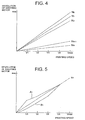
- the first correction coefficient Xn is determined so that it can be obtained as a value proportional to the printing speed V and corresponding to the printing image ratio N, as shown in FIG. 4 . In the example shown in FIG.
- X001, X012, X023, X034, and X04m in TABLE 1 are the same value, and similarly, Xn01, Xn12, Xn23, Xn34, and Xn4m are the same value.
- the second correction coefficient Yn is determined so that the standard revolution of the stepping motor 2 obtained using the first correction coefficient Xn can be increased or decreased so as to obtain the revolution of the stepping motor 2 suitable for feeding the necessary amount of ink for each printing image ratio when printing is performed at a predetermined speed using an ink type which must be fed in an amount different from that of a normal ink, such as an ink type which has lower color development than the normal ink and therefore must be fed in an increased amount, or an ink type which has higher color development than the normal ink and therefore must be fed in a reduced amount.
- the third correction coefficient Zn is a coefficient with which the acceleration coefficient Zan and the deceleration coefficient Zbn are determined.
- the acceleration coefficient Zan is determined in such a manner as to increase the standard revolution of the stepping motor 2 obtained with the abovementioned first correction coefficient Xn at an appropriate rate so that the stepping motor 2 can achieve a revolution exceeding the standard revolution during the acceleration period from the start of the printing press till the printing press reaches a predetermined printing speed (speed V4 in the figure) and so that the stepping motor 2 can achieve a revolution equal to the standard revolution during the period from the abovementioned predetermined printing speed till the printing press reaches the maximum printing speed to obtain an ink feed rate exceeding the standard ink feed rate.
- the deceleration coefficient Zbn is determined in such a manner as to decrease the standard revolution of the stepping motor 2 obtained with the abovementioned first correction coefficient Xn at an appropriate rate so that the stepping motor 2 can achieve a revolution less than the standard revolution, or so that the stepping motor 2 can stop at an ink feed stopping speed before the printing press, such an offset printing press, stops to obtain an ink feed rate less than the standard ink feed rate during the period from a predetermined printing speed (speed V4 in the figure) to the stop.
- FIG. 5 shows the standard revolutions of the stepping motor 2 corresponding to the acceleration side (A1) and the deceleration side (B1) in the printing image ratio N1. Similarly, acceleration and deceleration stages are provided for each case corresponding to the printing image ratios of N0, N2, ... Nn.
- the drive pulse output section 7 generates drive pulses for causing the stepping motor 2 to rotate at a revolution Rn of the stepping motor 2 needed for feed ink based on basic pulses of such a frequency as to cause the stepping motor 2 to rotate at a speed higher than the revolution Rm necessary to feed the largest amount of ink needed for printing by the printing press that are generated by the pulse generating section 8, and the revolution Rn.
- An exciting signal output section 9 generates an exciting signal that is fed to the motor coil of each phase of the stepping motor 2 based on the output of the drive pulse output section 7.
- a motor driver 10 amplifies the power of the exciting current output by the exciting signal output section 9 to feed an exciting current to the motor coil of the corresponding phase.
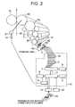
- FIG. 2 shows an example in which the present invention was applied to a newsprint offset press.
- a paper web W is passed between an impression cylinder IC and a blanket cylinder BC, and ink is fed to a printing plate having an eight-page content by an inking assembly IN to print an image on the printing plate on the paper web W via the surface of a blanket mounted on the blanket cylinder BC.
- the plate cylinder PC shown in FIG. 2 can hold a printing plate having a total of eight pages of a newspaper; four pages in the axial direction and two pages in the circumferential direction.
- the plate cylinder PC is divided into eight areas (columns) for each page-width of a news paper in the axial direction; an ink pump allocated for each area (column) and eight ink pumps being assembled into an ink pump unit PU for feeding ink over a full 1-page width of a newspaper on the plate cylinder PC.
- Each ink pump in the ink pump unit PU has an individual stepping motor 2 that is an ink pump drive motor.
- the stepping motor 2 is a motor that rotates in 200 angular steps (an angular step: 1.8 degrees), for example, whose revolving speed Rm for driving an ink pump to ensure the supply of the maximum required amount of ink for a printing operation, that is, the supply of a necessary and sufficient amount of ink to a column of the maximum image ratio (100%) is set to 120 revolutions per minute.
- the suction side of the ink pump is connected to an ink tank (not shown) with piping, and the delivery side thereof is connected to an ink rail IR of the inking assembly IN with piping.
- the figure shows the stepping motor 2 only for one ink pump unit PU, and similarly an exciting signal output section 9 and a motor driver 10 are shown in FIG. 2 only for one ink pump unit PU.
- a control unit 15 comprises a processing section 3, a memory section 4, a printing speed detecting section 5, a speed judgement section 6, a drive pulse output section 7, a pulse generating section 8, an exciting signal output section 9, and a motor driver 10.
- the functions and operations of these sections are as described earlier.
- numeral 11 refers to an image ratio input section, 12 to an ink designating section, 13 to a printing press pulse output section, 21 to a motor as a printing press drive unit, and 20 to a printing plate, respectively.
- the data on the printing operation are first input into the processing section 3. That is, the data on a printing image ratio for each column on the printing plate 20 obtained by some appropriate means are input from the image ratio input section 11.
- the ink used for the printing operation is designated by the ink designating section 12 as necessary.
- the processing section 3 fetches from the memory section 4 the first correction coefficient Xn corresponding to the input printing image ratio, that is, the "line" of the first correction coefficient Xn corresponding to the relevant image ratio in TABLE 1.
- the processing section 3 also fetches from the memory section 4 the second correction coefficient Yn corresponding to the input ink designation, that is, the "line" of the second correction coefficient Yn corresponding to the relevant designated ink in TABLE 2 (Steps S1 - S4).
- the printing press drive section 21 is activated to cause the printing press to start printing.
- the printing press pulse output section 13 connected to the printing press drive section 21 outputs pulses the number of which per unit of time is proportional to the revolving speed of the printing press drive section 21.
- This pulse output is processed in the printing speed detecting section 5 into a printing speed signal, which is output in the form of the number of output pulses per unit of time, or the revolution per unit of time of the driven components (the plate cylinder, etc.) obtained based on the number of output pulses, or other appropriate value based on these values (Step S5).
- the printing speed signal output by the printing speed detecting section 5 is brought in the processing section 3 and the speed judgement section 6.
- the speed judgement section 6 takes in the printing speed signal output by the printing speed detecting section 5 every predetermined hour, compares the currently taken-in printing speed signal with the previously taken-in printing speed signal to judge whether the operating speed of the printing press, that is, printing speed is accelerating or decelerating, or remains unchanged, and outputs the judgement result in the form of a signal.
- the speed judgement section 6 performs the judgement of printing speed only during the period from the start signal of the printing press till the printing press reach a predetermined normal operation printing speed and till the press comes to a halt upon receipt of the stop signal. Consequently, once the printing press reaches the normal operating speed upon receipt of a start signal, the speed judgement section 6 keeps outputting a no-acceleration/deceleration signal even if there is an acceleration or deceleration in printing speed during printing operation for some reason or other unless a deceleration is instructed by a stop signal (Step S6).
- the processing section 3 updates the signal output or the output signal. More specifically, the processing section 3 takes in the printing speed output by the printing speed detecting section 5 and the speed judgement result signal output by the speed judgement section 6.
- the third correction coefficient Zn corresponding to the speed judgement result that is, the "line" of the third correction coefficient Zn corresponding to the input speed judgement result in TABLE 3 is fetched from the memory section 4. Furthermore, the first correction coefficient Xn, the second correction coefficient Yn and the third correction coefficient Zn are decided based on the printing speed signal as the first correction coefficient Xk, the second correction coefficient Yk and the third correction coefficient Zk that are values corresponding to the relevant printing speeds (Steps S7 - S11).
- the ink feed correction coefficient Ik is calculated based on the decided first, second and third correction coefficients Xk, Yk and Zk by the following equation.
- Ik Xk ⁇ Yk ⁇ Zk .
- the signal corresponding to the calculated ink feed correction coefficient Ik, that is, the revolution of the stepping motor 2 corresponding to the ink feed correction coefficient Ik, that is, the revolution Rk of the stepping motor 2 needed for ink feeding for printing at the ink feed correction coefficient Ik is calculated by the following equation.
- Rk Ik ⁇ Rm + C C : a constant including 0
- the calculated revolution Rk of the stepping motor 2 is output in the form of an appropriate signal.
- the second correction coefficient Yn when there is no ink designation is "1," and the third correction coefficient Zn when there is no speed judgement result is "1.”
- C is a properly selected constant.
- the processing section 3 outputs a signal so that the revolution Rk of the stepping motor 2 gradually reaches the standard speed after the lapse of a predetermined time (Step S12).
- the signal designating the revolution Rk of the stepping motor 2 output by the processing section 3 is input into the drive pulse output section 7.
- the drive pulse output section 7 Upon receipt of the signal designating the revolution Rk of the stepping motor 2, the drive pulse output section 7 outputs a drive pulse obtained by reducing the basic pulse of 1 kHz, for example, into that of a frequency that can cause the stepping motor 2 to rotate at the revolution Rk designated by the processing section 3 (Step S13).
- the drive pulse output by the drive pulse output section 7 is input into the exciting signal output section 9.
- the exciting signal output section 9 Upon receipt of the drive pulse, the exciting signal output section 9 generates and outputs an exciting signal in accordance with the drive pulse, amplifying power via a motor driver 10, causing the stepping motor 2 to rotate at the revolution Rk designated by the processing section 3 (Steps S14 and S15).
- the printing press When the printing press is stopped with a stop signal to complete the printing operation, the printing press begins deceleration upon receipt of the stop signal, and performs the operations of Steps S5 through S15 until the printing press stops.
- the ink pump can be controlled so as to prevent an insufficient amount of ink from being fed to the printing press during the acceleration stage at the start of printing operation, and an excessive amount of ink from being fed during the deceleration stage at the end of printing operation. Even when an ink type having different color development is used, the ink pump can be operated to ensure a proper ink supply.
Landscapes
- Inking, Control Or Cleaning Of Printing Machines (AREA)
Claims (6)
- Farbpumpensteuervorrichtung zur Verwendung in einer Druckpresse durch Ändern der Zufuhrgeschwindigkeit von Farbe durch eine Farbpumpe (1) auf der Basis von Druckbildverhältnis und Druckgeschwindigkeit, wobei die Farbpumpensteuervorrichtung Folgendes umfasst:einen Bildverhältniseingabeteil (11) zum Eingeben von Daten, die einem Druckbildverhältnis für einen Bereich eines Druckmaterials entsprechen, dem Farbe zugeführt wird;einen Druckgeschwindigkeitserfassungsteil (5) zum Erfassen der Druckgeschwindigkeit der Druckpresse und zum Ausgeben eines Druckgeschwindigkeitssignals, das der Druckgeschwindigkeit entspricht;einen Geschwindigkeitsbeurteilungsteil (6) zum Beurteilen von Änderungen der Druckgeschwindigkeit auf der Basis des vom Druckgeschwindigkeitserfassungsteil (5) ausgegebenen Druckgeschwindigkeitssignals;einen Speicherteil (4) zum Speichern von ersten Korrekturkoeffizienten, die nach Druckbildverhältnissen bestimmt werden, und von dritten Korrekturkoeffizienten, die nach Erhöhungen und Verringerungen der Druckgeschwindigkeit bestimmt werden; undeinen Verarbeitungsteil (3) zum Abrufen der ersten und dritten Korrekturkoeffizienten aus dem Speicherteil (4) auf der Basis von Daten, die den eingegebenen Druckbildverhältnissen und dem vom Geschwindigkeitsbeurteilungsteil (6) ausgegebenen Ergebnis der Geschwindigkeitsänderungsbeurteilung entsprechen, um von diesen Koeffizienten und der Druckgeschwindigkeit einen Farbzufuhrkorrekturkoeffizienten zu berechnen und ein Signal zum Betätigen der Farbpumpe (1) auszugeben, so dass die um den Farbzufuhrkorrekturkoeffizienten korrigierte Farbmenge zugeführt werden kann,wobei die Farbpumpensteuervorrichtung den Betrieb der Farbpumpe (1) auf der Basis von Daten steuert, die dem Druckbildverhältnis, dem Geschwindigkeitsänderungsergebnis und der Druckgeschwindigkeit entsprechen.
- Farbpumpensteuervorrichtung nach Anspruch 1, die ferner einen Farbbezeichnungsteil zum Bezeichnen des verwendeten Farbtyps umfasst, in dem der Speicherteil (4) nach Farbtyp bestimmte zweite Korrekturkoeffizienten speichert und in dem der Verarbeitungsteil (3) die Aufgabe hat, zusätzlich den zweiten Korrekturkoeffizienten aus dem Speicherteil (4) abzurufen, und in dem der Farbzufuhrkorrekturkoeffizient zusätzlich mittels des zweiten Korrekturkoeffizienten berechnet wird.
- Farbpumpensteuervorrichtung nach Anspruch 2, wobei die zweiten Korrekturkoeffizienten zum Erhöhen oder Verringern der Standarddrehgeschwindigkeit dienen, die auf der Basis des ersten Korrekturkoeffizienten mit einem geeigneten Verhältnis berechnet wird, damit die Antriebseinheiten (2) der Farbpumpe (1) auf eine zum Zuführen einer benötigten Farbmenge gemäß der Farbbezeichnung für jedes Druckbildverhältnis geeignete Weise gesteuert werden können.
- Farbpumpensteuervorrichtung nach einem der vorherigen Ansprüche, wobei die ersten Korrekturkoeffizienten zum Berechnen der Standarddrehgeschwindigkeit von Antriebseinheiten (2) der Farbpumpen (2) dienen, die eine benötigte Farbmenge für einen Druckbetrieb mit einer vorbestimmten Geschwindigkeit für jedes Druckbildverhältnis zuführen.
- Farbpumpensteuervorrichtung nach einem der vorherigen Ansprüche, wobei die dritten Korrekturkoeffizienten Beschleunigungskoeffizienten oder Verlangsamungskoeffizienten sind; wobei die Beschleunigungskoeffizienten zum Erhöhen der Standarddrehgeschwindigkeit dienen, die auf der Basis der ersten Korrekturkoeffizienten mit einem geeigneten Verhältnis in der Beschleunigungsphase berechnet wurde, bis die Druckpresse eine vorbestimmte Druckgeschwindigkeit erreicht, und die Verlangsamungskoeffizienten zum Verringern der Standarddrehgeschwindigkeit dienen, die auf der Basis der ersten Korrekturkoeffizienten mit einem geeigneten Verhältnis während der Verlangsamungsphase berechnet wurde, bis die Druckpresse von der vorbestimmten Druckgeschwindigkeit verlangsamt wird.
- Farbpumpensteuervorrichtung nach einem der vorherigen Ansprüche, wobei der Geschwindigkeitsbeurteilungsteil (6) die Aufgabe hat, Änderungen der Druckgeschwindigkeit in der Periode ab dem Start der Druckpresse auf der Basis eines Startsignals zu beurteilen, bis die Druckpresse eine vorbestimmte Normalbetriebsdruckgeschwindigkeit erreicht und bis die Druckpresse auf der Basis eines Stoppsignals zum Stillstand kommt.
Applications Claiming Priority (2)
| Application Number | Priority Date | Filing Date | Title |
|---|---|---|---|
| JP2000339791A JP3428578B2 (ja) | 2000-11-08 | 2000-11-08 | インキポンプ制御装置 |
| JP2000339791 | 2000-11-08 |
Publications (3)
| Publication Number | Publication Date |
|---|---|
| EP1205299A2 EP1205299A2 (de) | 2002-05-15 |
| EP1205299A3 EP1205299A3 (de) | 2003-01-22 |
| EP1205299B1 true EP1205299B1 (de) | 2009-07-08 |
Family
ID=18814810
Family Applications (1)
| Application Number | Title | Priority Date | Filing Date |
|---|---|---|---|
| EP01307133A Expired - Lifetime EP1205299B1 (de) | 2000-11-08 | 2001-08-22 | Farbpumpensteuervorrichtung |
Country Status (4)
| Country | Link |
|---|---|
| US (1) | US6629497B2 (de) |
| EP (1) | EP1205299B1 (de) |
| JP (1) | JP3428578B2 (de) |
| DE (1) | DE60139177D1 (de) |
Families Citing this family (7)
| Publication number | Priority date | Publication date | Assignee | Title |
|---|---|---|---|---|
| JP4139012B2 (ja) * | 1999-09-06 | 2008-08-27 | 株式会社小森コーポレーション | 印刷機のインキ供給量調整方法および装置 |
| JP3428578B2 (ja) * | 2000-11-08 | 2003-07-22 | 株式会社東京機械製作所 | インキポンプ制御装置 |
| JP2007030348A (ja) * | 2005-07-27 | 2007-02-08 | Komori Corp | 印刷機のインキ供給量調整方法および装置 |
| ITMO20070302A1 (it) * | 2007-10-03 | 2009-04-04 | Antonio Maccari | Metodi e dispositivi per controllare il funzionamento di macchine decoratrici |
| US20130291745A1 (en) * | 2012-05-01 | 2013-11-07 | Goss International Americas, Inc. | Method and system for instantaneously determining printing fluid volume consumed in a printing press |
| DE112017000637T5 (de) * | 2016-02-03 | 2018-10-31 | Hangzhou Cron Intelligent Printing Technology Co., Ltd | Ein digitaler Farbkasten für eine Druckmaschine und ein digitales Farbversorgungssystem sowie dessen Anwendungsverfahren |
| JP7412067B2 (ja) * | 2017-05-09 | 2024-01-12 | コニカミノルタ株式会社 | 印刷装置および印刷方法 |
Family Cites Families (10)
| Publication number | Priority date | Publication date | Assignee | Title |
|---|---|---|---|---|
| US3608486A (en) * | 1969-04-28 | 1971-09-28 | Hoe & Co R | Drive means for the inking mechanism of a printing machine |
| JPH01174446A (ja) | 1987-12-29 | 1989-07-11 | Mitsubishi Heavy Ind Ltd | インキポンプ制御装置 |
| JPH01174447A (ja) | 1987-12-29 | 1989-07-11 | Mitsubishi Heavy Ind Ltd | インキポンプ制御装置 |
| US5182993A (en) * | 1989-03-02 | 1993-02-02 | Tokyo Kikai Seisakusho, Ltd. | Ink supply source driving apparatus for rotary presses |
| EP0422365B1 (de) * | 1989-09-29 | 1994-12-07 | Rockwell International Corporation | Farb- und Wassermehrfachkurven für Druckmaschinen |
| JP2622072B2 (ja) * | 1993-08-18 | 1997-06-18 | 株式会社東京機械製作所 | インキポンプの制御装置 |
| JP2644181B2 (ja) * | 1994-03-04 | 1997-08-25 | 株式会社東京機械製作所 | インキポンプの制御装置 |
| US5957051A (en) * | 1997-06-30 | 1999-09-28 | Atwater; Richard G. | Single width press with digital ink injection |
| DE19847767A1 (de) * | 1998-10-16 | 2000-04-20 | Decoufle Sarl | Anordnung zum Zuführen von fließfähiger Druckfarbe zu einem Druckwerk für einen Zigarettenpapierstreifen |
| JP3428578B2 (ja) * | 2000-11-08 | 2003-07-22 | 株式会社東京機械製作所 | インキポンプ制御装置 |
-
2000
- 2000-11-08 JP JP2000339791A patent/JP3428578B2/ja not_active Expired - Fee Related
-
2001
- 2001-08-22 DE DE60139177T patent/DE60139177D1/de not_active Expired - Lifetime
- 2001-08-22 EP EP01307133A patent/EP1205299B1/de not_active Expired - Lifetime
- 2001-08-29 US US09/942,348 patent/US6629497B2/en not_active Expired - Fee Related
Also Published As
| Publication number | Publication date |
|---|---|
| US20020078845A1 (en) | 2002-06-27 |
| EP1205299A2 (de) | 2002-05-15 |
| EP1205299A3 (de) | 2003-01-22 |
| JP2002144531A (ja) | 2002-05-21 |
| DE60139177D1 (de) | 2009-08-20 |
| JP3428578B2 (ja) | 2003-07-22 |
| US6629497B2 (en) | 2003-10-07 |
Similar Documents
| Publication | Publication Date | Title |
|---|---|---|
| CA1208971A (en) | Method and apparatus for reducing register errors in multi-colour rotary printing presses | |
| EP0816074B1 (de) | Verfahren zur Regelung der Schichtdicke eines Farbfilms für eine Farbzuführeinrichtung | |
| EP0812682B1 (de) | Antrieb für eine Druckmaschine | |
| JP2000052540A (ja) | 複数のウェブを備えた輪転印刷機の色/カットレジスタ制御の自動調節方法 | |
| DE10132266B4 (de) | Verfahren zur Regelung des Übergabepassers in einer Bogenrotationsdruckmaschine | |
| JPH10157054A (ja) | 印刷機用の駆動装置 | |
| US6298779B1 (en) | Rotary press | |
| DE4444755A1 (de) | Vorrichtung zum Fördern von Bogen im Anlegerbereich einer bogenverarbeitenden Maschine | |
| US20010032558A1 (en) | Ink film thickness control method and apparatus for multi-color printing press | |
| US20020029706A1 (en) | Determining the presetting data for the cut register and/or color register (circumferential register) for printing mechanisms with no lineshaft | |
| EP1205299A2 (de) | Farbpumpensteuervorrichtung | |
| US7121208B2 (en) | Method of setting optimized pre-inking prior to the start of printing the current print job | |
| JP3331241B2 (ja) | 多数の印刷ユニットを備えた印刷機械の駆動装置 | |
| US7028616B2 (en) | Ink supply amount control method and apparatus for printing press | |
| US6427590B1 (en) | Drive for a printing press with a plurality of printing units | |
| US6679172B2 (en) | Control apparatus and method for automatically changing plate cylinders in rotary press | |
| GB2270035A (en) | Printing press with a plurality of printing units and drive control therefor. | |
| US6915737B2 (en) | Ink supply amount control method and apparatus for printing press | |
| US5575208A (en) | Ink pump control system | |
| DE4218761A1 (de) | Verfahren zum Voreinstellen von Registereinstellvorrichtungen an Rotationsdruckmaschinen | |
| DE102004048151B4 (de) | Verfahren zur Optimierung von Antriebsreglern | |
| EP0668824A1 (de) | Verfahren zur beeinflussung der farbdichte eines druckfarbeauftrages auf einem druckträger. | |
| JPH07266548A (ja) | 輪転印刷機 | |
| JP2964229B2 (ja) | 湿し水供給装置 | |
| JP3993425B2 (ja) | オフセット輪転印刷機及びその速度制御方法 |
Legal Events
| Date | Code | Title | Description |
|---|---|---|---|
| PUAI | Public reference made under article 153(3) epc to a published international application that has entered the european phase |
Free format text: ORIGINAL CODE: 0009012 |
|
| AK | Designated contracting states |
Kind code of ref document: A2 Designated state(s): AT BE CH CY DE DK ES FI FR GB GR IE IT LI LU MC NL PT SE TR |
|
| AX | Request for extension of the european patent |
Free format text: AL;LT;LV;MK;RO;SI |
|
| PUAL | Search report despatched |
Free format text: ORIGINAL CODE: 0009013 |
|
| AK | Designated contracting states |
Kind code of ref document: A3 Designated state(s): AT BE CH CY DE DK ES FI FR GB GR IE IT LI LU MC NL PT SE TR |
|
| AX | Request for extension of the european patent |
Free format text: AL;LT;LV;MK;RO;SI |
|
| 17P | Request for examination filed |
Effective date: 20030314 |
|
| AKX | Designation fees paid |
Designated state(s): CH DE GB LI |
|
| 17Q | First examination report despatched |
Effective date: 20060728 |
|
| GRAP | Despatch of communication of intention to grant a patent |
Free format text: ORIGINAL CODE: EPIDOSNIGR1 |
|
| GRAS | Grant fee paid |
Free format text: ORIGINAL CODE: EPIDOSNIGR3 |
|
| GRAA | (expected) grant |
Free format text: ORIGINAL CODE: 0009210 |
|
| AK | Designated contracting states |
Kind code of ref document: B1 Designated state(s): CH DE GB LI |
|
| REG | Reference to a national code |
Ref country code: GB Ref legal event code: FG4D |
|
| REG | Reference to a national code |
Ref country code: CH Ref legal event code: EP |
|
| REF | Corresponds to: |
Ref document number: 60139177 Country of ref document: DE Date of ref document: 20090820 Kind code of ref document: P |
|
| PGFP | Annual fee paid to national office [announced via postgrant information from national office to epo] |
Ref country code: DE Payment date: 20090831 Year of fee payment: 9 |
|
| REG | Reference to a national code |
Ref country code: CH Ref legal event code: PL |
|
| PG25 | Lapsed in a contracting state [announced via postgrant information from national office to epo] |
Ref country code: CH Free format text: LAPSE BECAUSE OF NON-PAYMENT OF DUE FEES Effective date: 20090831 Ref country code: LI Free format text: LAPSE BECAUSE OF NON-PAYMENT OF DUE FEES Effective date: 20090831 |
|
| PLBE | No opposition filed within time limit |
Free format text: ORIGINAL CODE: 0009261 |
|
| STAA | Information on the status of an ep patent application or granted ep patent |
Free format text: STATUS: NO OPPOSITION FILED WITHIN TIME LIMIT |
|
| 26N | No opposition filed |
Effective date: 20100409 |
|
| PG25 | Lapsed in a contracting state [announced via postgrant information from national office to epo] |
Ref country code: GB Free format text: LAPSE BECAUSE OF NON-PAYMENT OF DUE FEES Effective date: 20091008 |
|
| REG | Reference to a national code |
Ref country code: DE Ref legal event code: R119 Ref document number: 60139177 Country of ref document: DE Effective date: 20110301 |
|
| PG25 | Lapsed in a contracting state [announced via postgrant information from national office to epo] |
Ref country code: DE Free format text: LAPSE BECAUSE OF NON-PAYMENT OF DUE FEES Effective date: 20110301 |