EP1205421A1 - Procédé et dispositif pour transporter des grues à tour en treillis - Google Patents
Procédé et dispositif pour transporter des grues à tour en treillis Download PDFInfo
- Publication number
- EP1205421A1 EP1205421A1 EP01250384A EP01250384A EP1205421A1 EP 1205421 A1 EP1205421 A1 EP 1205421A1 EP 01250384 A EP01250384 A EP 01250384A EP 01250384 A EP01250384 A EP 01250384A EP 1205421 A1 EP1205421 A1 EP 1205421A1
- Authority
- EP
- European Patent Office
- Prior art keywords
- counterweight
- intermediate piece
- transport
- boom
- counterweight element
- Prior art date
- Legal status (The legal status is an assumption and is not a legal conclusion. Google has not performed a legal analysis and makes no representation as to the accuracy of the status listed.)
- Withdrawn
Links
- 238000000034 method Methods 0.000 title claims abstract description 11
- 239000002184 metal Substances 0.000 claims description 2
- 230000032258 transport Effects 0.000 claims 4
- 238000010276 construction Methods 0.000 description 3
- 125000006850 spacer group Chemical group 0.000 description 3
- 238000011161 development Methods 0.000 description 2
- 230000018109 developmental process Effects 0.000 description 2
- 230000001419 dependent effect Effects 0.000 description 1
- 238000011038 discontinuous diafiltration by volume reduction Methods 0.000 description 1
- 230000002349 favourable effect Effects 0.000 description 1
- 238000003780 insertion Methods 0.000 description 1
- 230000037431 insertion Effects 0.000 description 1
- 238000005457 optimization Methods 0.000 description 1
- 239000007787 solid Substances 0.000 description 1
Images

Classifications
-
- B—PERFORMING OPERATIONS; TRANSPORTING
- B66—HOISTING; LIFTING; HAULING
- B66C—CRANES; LOAD-ENGAGING ELEMENTS OR DEVICES FOR CRANES, CAPSTANS, WINCHES, OR TACKLES
- B66C23/00—Cranes comprising essentially a beam, boom, or triangular structure acting as a cantilever and mounted for translatory of swinging movements in vertical or horizontal planes or a combination of such movements, e.g. jib-cranes, derricks, tower cranes
- B66C23/62—Constructional features or details
- B66C23/64—Jibs
- B66C23/70—Jibs constructed of sections adapted to be assembled to form jibs or various lengths
-
- B—PERFORMING OPERATIONS; TRANSPORTING
- B66—HOISTING; LIFTING; HAULING
- B66C—CRANES; LOAD-ENGAGING ELEMENTS OR DEVICES FOR CRANES, CAPSTANS, WINCHES, OR TACKLES
- B66C23/00—Cranes comprising essentially a beam, boom, or triangular structure acting as a cantilever and mounted for translatory of swinging movements in vertical or horizontal planes or a combination of such movements, e.g. jib-cranes, derricks, tower cranes
- B66C23/62—Constructional features or details
- B66C23/72—Counterweights or supports for balancing lifting couples
- B66C23/74—Counterweights or supports for balancing lifting couples separate from jib
Definitions
- the invention relates to a method for transporting Lattice boom cranes including counterweights according to the The preamble of claim 1 and a device for Performing this procedure.
- a mobile crane is described in DE-AS 1 279 904, whose lattice boom is composed of spacers which have a rectangular cross section, which is along the longitudinal axis from the foot area to the head area of the Cantilever continuously tapered. Therefore, individual Slide spacers into one another for transport Achieve volume reduction. For intermediate pieces that this is a constant cross-section not possible.
- a tower crane is known from DE-GM 1 937 030, whose tower is composed of intermediate pieces, the are each formed from elbows that releasably connected and in the same number are present like the sides of the tower, each Flat leg of an elbow has a width that the Half of the width of the tower side corresponds. in the disassembled state the contra-angles Stack into each other to save space. This is at Intermediate pieces, which form a solid structural unit, not possible.
- This document also mentions that in Inside the construction space that the collapsed tower forms also other crane parts such as a crane ladder can be. This corresponds to that mentioned at the beginning Procedure, smaller intermediate pieces of a jib to be inserted into larger intermediate pieces of a main boom.
- the object of the invention is to provide a method for transporting Specify lattice boom cranes, regardless of which Training of an auxiliary boom as well as a dismantling and a constant cross-section of the respective Boom spacers the required number of Transport movements can be significantly reduced.
- lattice mast elements of Boom for the transport of counterweight elements used for the transport of counterweight elements used, the counterweight elements in or on the each lattice mast element are secured in place.
- the attachment can be frictional; however, it is preferred form-fitting.
- a device is used to implement the method a counterweight element and one as a lattice mast element trained intermediate piece proposed to the End faces with at least one attachment point provided connecting element and thereby is characterized in that at least one counterweight element can be secured in position or on the intermediate piece.
- Counterweight element with the inside of the side wall of the Connecting piece. This is done on the inside a mounting frame arranged as a guide and in this the counterweight element inserted and secured.
- the It can be inserted either from above, from the side or from from the front.
- a backup is by means of Bolts, straps, chain, screws or clamps possible.
- the Mounting frame is preferably made of sheet metal profiles composed, depending on the direction of insertion of the Weight element one up, to the side or to the Form an open U towards the front.
- the Fastening frame composed of angle plates and form an L.
- a less preferred method is that Counterweight element from the end face of the intermediate piece to lay on the inside of the lower chord side, whereby the Dead weight forms part of the positional security system an additional attachment is added.
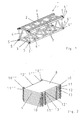
- Figure 1 shows a perspective view of a well-known intermediate piece prepared for transport 1 in lattice mast construction. It's rectangular in cross section, in particular square and points in this Embodiment an upper chord side 2, a lower chord side 3 and two side walls 4,4 '.
- the end areas of the Intermediate piece 1 are here with two or three Fastening points 5, 5 ', 6-6 " Provide fasteners.
- intermediate piece 1 is already for transport prepared when the corresponding guy rods 7 already are stored on the upper side 2.
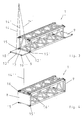
- Figure 2 also shows a perspective view a stack designed according to the invention Counterweight elements 8.9. Both counterweight elements 8.9 are in the four corner areas, each with an attachment point 10-10 '' ', 11-11' ''. In addition, everyone is Counterweight element 8.9 on two opposite sides at least one eyelet 12-12 ", 13-13" arranged to the counterweight element 8.9 regardless of the Attach attachment points 10-10 ", 11-11" to a hoist to be able to.
- the first step is a counterweight plate 8.9 using the lifting eyes 12-12 ", 13-13" in the End region of the intermediate piece 1 filed.
- the filing takes place in such a way that the Attachment points 10.10 'of the intermediate piece Counterweight element 8 between the two Fastening points 5.5 'of the intermediate piece 1 inserted become.
- the two inner ropes 14, 14 'loosened and the two below lying bolts 15, 15 ' In Figure 4, the Steps 3 and 4 shown.
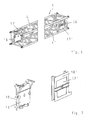
- FIG 5 is also a perspective Representation of a less preferred attachment of Counterweight elements 17, 17 'in an intermediate piece 1 shown.
- the attachment is made here that the respective counterweight 17.17 'on the inside of the Lower belt side 3 of the intermediate piece 1 deposited and through his own weight and one not shown Attachment to the adapter 1 in its position for the Transport is secured immovably.
- the disadvantage is that there is a need for special lifting equipment in order to Counterweight element 17,17 'from the front of the To be able to insert intermediate piece 1 inwards.
- FIG. 6 A preferred alternative to this is shown in FIG. 6.
- 4.4 'of the on each side wall Intermediate piece 1 a mounting frame 18, 18 'each arranged.
- the details of this are shown in FIG. 7.
- the Mounting frame 18, 18 ' is in this embodiment designed so that the respective counterweight element 17, 17 'from above into the mounting frame 18, 18' can be inserted and secured.
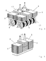
- FIG. 8 shows a stack example for a counterbalance wagon and Figure 9 shows a stack example of a base support plate of a lattice boom crane.
- the reference symbols used therein correspond to those of the other figures.
Landscapes
- Engineering & Computer Science (AREA)
- Mechanical Engineering (AREA)
- Jib Cranes (AREA)
Applications Claiming Priority (2)
| Application Number | Priority Date | Filing Date | Title |
|---|---|---|---|
| DE10056647A DE10056647A1 (de) | 2000-11-09 | 2000-11-09 | Verfahren zum Transport von Gittermastkranen |
| DE10056647 | 2000-11-09 |
Publications (1)
| Publication Number | Publication Date |
|---|---|
| EP1205421A1 true EP1205421A1 (fr) | 2002-05-15 |
Family
ID=7663422
Family Applications (1)
| Application Number | Title | Priority Date | Filing Date |
|---|---|---|---|
| EP01250384A Withdrawn EP1205421A1 (fr) | 2000-11-09 | 2001-11-01 | Procédé et dispositif pour transporter des grues à tour en treillis |
Country Status (3)
| Country | Link |
|---|---|
| US (1) | US20020053551A1 (fr) |
| EP (1) | EP1205421A1 (fr) |
| DE (1) | DE10056647A1 (fr) |
Cited By (4)
| Publication number | Priority date | Publication date | Assignee | Title |
|---|---|---|---|---|
| EP2065332A3 (fr) * | 2007-11-29 | 2011-11-02 | Manitowoc Crane Companies, Inc. | Système pour connecter segments de flêche de grue |
| US9051159B2 (en) | 2012-12-20 | 2015-06-09 | Manitowoc Crane Companies, Llc | Column connector system |
| US9121425B2 (en) | 2007-11-29 | 2015-09-01 | Manitowoc Crane Companies, Llc | Connection system for crane components |
| CN105439011A (zh) * | 2015-12-25 | 2016-03-30 | 同济大学 | 用于臂架式起重机的自组装装置及其使用方法 |
Families Citing this family (6)
| Publication number | Priority date | Publication date | Assignee | Title |
|---|---|---|---|---|
| NL1020779C2 (nl) * | 2002-06-06 | 2003-12-09 | Mammoet Holding B V | Werkwijze voor het gereedmaken voor transport van een ringkraan. |
| DE102007050907A1 (de) * | 2007-10-23 | 2009-04-30 | Benteler Automobiltechnik Gmbh | Verfahren zur Herstellung eines gehärteten Blechprofils |
| DE102012001377B4 (de) * | 2011-12-01 | 2023-12-28 | Liebherr-Werk Ehingen Gmbh | Ballastwagen für einen Derrickkran |
| US9352941B2 (en) * | 2012-03-20 | 2016-05-31 | Alion Energy, Inc. | Gantry crane vehicles and methods for photovoltaic arrays |
| DE202016003698U1 (de) * | 2016-06-13 | 2017-09-14 | Liebherr-Werk Ehingen Gmbh | Mobilkran |
| US11866307B2 (en) * | 2022-04-26 | 2024-01-09 | Caterpillar Inc. | Configuration of a structural support for a boom of a pipelayer machine |
Citations (3)
| Publication number | Priority date | Publication date | Assignee | Title |
|---|---|---|---|---|
| DE1937030U (de) * | 1965-02-23 | 1966-04-21 | Richer S A | Turmkran, fachwerkmast od. dgl. |
| DE1279904B (de) * | 1967-04-06 | 1968-10-10 | Coles Krane G M B H | Auslegermast fuer Krane |
| DE29718157U1 (de) * | 1997-10-14 | 1998-02-19 | Noell Service und Maschinentechnik GmbH, 54294 Trier | Transporteinheit für Turmelemente von Turmdrehkränen |
-
2000
- 2000-11-09 DE DE10056647A patent/DE10056647A1/de not_active Withdrawn
-
2001
- 2001-11-01 EP EP01250384A patent/EP1205421A1/fr not_active Withdrawn
- 2001-11-08 US US10/008,020 patent/US20020053551A1/en not_active Abandoned
Patent Citations (3)
| Publication number | Priority date | Publication date | Assignee | Title |
|---|---|---|---|---|
| DE1937030U (de) * | 1965-02-23 | 1966-04-21 | Richer S A | Turmkran, fachwerkmast od. dgl. |
| DE1279904B (de) * | 1967-04-06 | 1968-10-10 | Coles Krane G M B H | Auslegermast fuer Krane |
| DE29718157U1 (de) * | 1997-10-14 | 1998-02-19 | Noell Service und Maschinentechnik GmbH, 54294 Trier | Transporteinheit für Turmelemente von Turmdrehkränen |
Cited By (9)
| Publication number | Priority date | Publication date | Assignee | Title |
|---|---|---|---|---|
| EP2065332A3 (fr) * | 2007-11-29 | 2011-11-02 | Manitowoc Crane Companies, Inc. | Système pour connecter segments de flêche de grue |
| US8534474B2 (en) | 2007-11-29 | 2013-09-17 | Manitowoc Crane Companies, Llc | Connection system for crane boom segments |
| EP2818443A1 (fr) * | 2007-11-29 | 2014-12-31 | Manitowoc Crane Companies, LLC | Système de connexion pour segments de flèche de grue |
| US9121425B2 (en) | 2007-11-29 | 2015-09-01 | Manitowoc Crane Companies, Llc | Connection system for crane components |
| US9187296B2 (en) | 2007-11-29 | 2015-11-17 | Manitowoc Crane Companies, Llc | Connection system for crane column segments |
| EP3028982A1 (fr) * | 2007-11-29 | 2016-06-08 | Manitowoc Crane Companies, LLC | Système de connexion pour segments de flèche de grue |
| US9051159B2 (en) | 2012-12-20 | 2015-06-09 | Manitowoc Crane Companies, Llc | Column connector system |
| CN105439011A (zh) * | 2015-12-25 | 2016-03-30 | 同济大学 | 用于臂架式起重机的自组装装置及其使用方法 |
| CN105439011B (zh) * | 2015-12-25 | 2017-06-13 | 同济大学 | 用于臂架式起重机的自组装装置及其使用方法 |
Also Published As
| Publication number | Publication date |
|---|---|
| US20020053551A1 (en) | 2002-05-09 |
| DE10056647A1 (de) | 2002-05-23 |
Similar Documents
| Publication | Publication Date | Title |
|---|---|---|
| EP1935833B1 (fr) | Elément de grille pour une grande grue mobile et son procédé de montage | |
| DE112019004917T5 (de) | Faltbarer Traversenauslegerabschnitt, Traversenausleger und Kran | |
| DE20203687U1 (de) | Unterflaschensystem | |
| EP3040303A2 (fr) | Grue et element de mat en treillis pour un mat en treillis pour une telle grue | |
| EP1939135B1 (fr) | Grue automotrice | |
| DE202021106818U1 (de) | Mobilkran mit einer Gegengewichtsvorrichtung | |
| DE2843025B2 (de) | Greifvorrichtung | |
| EP1205421A1 (fr) | Procédé et dispositif pour transporter des grues à tour en treillis | |
| DE202012013346U1 (de) | Anbauverdichter | |
| DE202019106049U1 (de) | Schwerlast-Prüfgewichteinheit zur Belastungsprüfung von Krananlagen | |
| DE2103667A1 (de) | Hebekran | |
| DE1932393A1 (de) | Verfahren zum Anheben einer monolithischen Zelle,welche Teil eines Gebaeudes,insbesondere dessen Abdeckung ist,auf eine bestimmte Hoehe zur Durchfuehrung dieses Verfahrens | |
| EP1213254A1 (fr) | Flèche télescopique | |
| EP4488221A1 (fr) | Grue avec un ballast de type à effet dechirement | |
| DE2949403A1 (de) | Geruest und zugehoeriges querelement | |
| DE8235609U1 (de) | Hub- und absetzvorrichtung fuer transportable raumzellen, baubuden, grossbehaelter oder dergl. | |
| DE102023109566B4 (de) | Mobilkran mit Gegengewichtsvorrichtung, Gegengewichtsvorrichtung sowie Verfahren zur Montage einer solchen | |
| DE2404147A1 (de) | Hebejoch mit gewichtsausgleich insbesondere zum transportieren von ueberlangen raumelementen aus beton | |
| DE102022117472B4 (de) | Hilfsspitze für den Ausleger eines Arbeitsgeräts | |
| DE102019114913A1 (de) | Montageadapter, Sicherheitsgeländer, Bausatz für ein Baugerüst sowie Baugerüst und Verfahren hierfür | |
| DE2138990C3 (de) | Überflur-Hebebühne | |
| DE2721268A1 (de) | Verfahren und vorrichtung fuer den aufbau des masts eines turmkrans, insbesondere eines krans grosser leistungsfaehigkeit | |
| DE1227632B (de) | Schornstein mit Fachwerkgeruest und Verfahren zu seiner Montage | |
| DE2305425A1 (de) | Vorrichtung zum errichten von kranmasten | |
| DE3246217A1 (de) | Gittermastausleger fuer einen auslegerkran |
Legal Events
| Date | Code | Title | Description |
|---|---|---|---|
| PUAI | Public reference made under article 153(3) epc to a published international application that has entered the european phase |
Free format text: ORIGINAL CODE: 0009012 |
|
| AK | Designated contracting states |
Kind code of ref document: A1 Designated state(s): AT BE CH CY DE DK ES FI FR GB GR IE IT LI LU MC NL PT SE TR |
|
| AX | Request for extension of the european patent |
Free format text: AL;LT;LV;MK;RO;SI |
|
| 17P | Request for examination filed |
Effective date: 20020716 |
|
| STAA | Information on the status of an ep patent application or granted ep patent |
Free format text: STATUS: THE APPLICATION HAS BEEN WITHDRAWN |
|
| AKX | Designation fees paid |
Designated state(s): AT BE CH CY DE DK ES FI FR GB GR IE IT LI LU MC NL PT SE TR |
|
| 18W | Application withdrawn |
Effective date: 20030110 |