EP1205422B1 - Vorrichtung zum Ballastieren eines Krans - Google Patents
Vorrichtung zum Ballastieren eines Krans Download PDFInfo
- Publication number
- EP1205422B1 EP1205422B1 EP01120276A EP01120276A EP1205422B1 EP 1205422 B1 EP1205422 B1 EP 1205422B1 EP 01120276 A EP01120276 A EP 01120276A EP 01120276 A EP01120276 A EP 01120276A EP 1205422 B1 EP1205422 B1 EP 1205422B1
- Authority
- EP
- European Patent Office
- Prior art keywords
- links
- hooks
- sides
- ballast
- ballast plates
- Prior art date
- Legal status (The legal status is an assumption and is not a legal conclusion. Google has not performed a legal analysis and makes no representation as to the accuracy of the status listed.)
- Expired - Lifetime
Links
- 230000008878 coupling Effects 0.000 claims abstract description 12
- 238000010168 coupling process Methods 0.000 claims abstract description 12
- 238000005859 coupling reaction Methods 0.000 claims abstract description 12
- 239000000725 suspension Substances 0.000 claims abstract 5
- 239000011324 bead Substances 0.000 claims description 3
- 230000000295 complement effect Effects 0.000 claims description 3
- 230000000630 rising effect Effects 0.000 claims description 2
- 230000005484 gravity Effects 0.000 description 5
- 230000000694 effects Effects 0.000 description 3
- 229910000831 Steel Inorganic materials 0.000 description 2
- 239000010959 steel Substances 0.000 description 2
- 229910001018 Cast iron Inorganic materials 0.000 description 1
- 241001236644 Lavinia Species 0.000 description 1
- 230000015572 biosynthetic process Effects 0.000 description 1
- 230000000903 blocking effect Effects 0.000 description 1
- 239000004567 concrete Substances 0.000 description 1
- 238000000151 deposition Methods 0.000 description 1
- 210000000629 knee joint Anatomy 0.000 description 1
- 210000002414 leg Anatomy 0.000 description 1
- NJPPVKZQTLUDBO-UHFFFAOYSA-N novaluron Chemical compound C1=C(Cl)C(OC(F)(F)C(OC(F)(F)F)F)=CC=C1NC(=O)NC(=O)C1=C(F)C=CC=C1F NJPPVKZQTLUDBO-UHFFFAOYSA-N 0.000 description 1
- 210000000689 upper leg Anatomy 0.000 description 1
Images


Classifications
-
- B—PERFORMING OPERATIONS; TRANSPORTING
- B66—HOISTING; LIFTING; HAULING
- B66C—CRANES; LOAD-ENGAGING ELEMENTS OR DEVICES FOR CRANES, CAPSTANS, WINCHES, OR TACKLES
- B66C23/00—Cranes comprising essentially a beam, boom, or triangular structure acting as a cantilever and mounted for translatory of swinging movements in vertical or horizontal planes or a combination of such movements, e.g. jib-cranes, derricks, tower cranes
- B66C23/62—Constructional features or details
- B66C23/72—Counterweights or supports for balancing lifting couples
- B66C23/74—Counterweights or supports for balancing lifting couples separate from jib
Definitions
- this object is achieved in that the hitches consist of hooks with outwardly directed hook tines and that the Coupling part of two articulated on a connected to the hoist rope holding part pivotally mounted equal length handlebars is formed at their free ends Wear eyelets and provided with a detachable, this spreading spreader are.
- the ballast plates can be easily characterized take and settle that the ends of the spread arms on both sides the hook placed on the line connecting the hook, the spreader in the manner is solved by lifting the holding part, the ends of the handlebars to run under gravity so that the eyelets run into the hook and be caught by them as it were.
- This allows the ballast plates without hand-hanging with the scissors-like lifting couple the Hubseils closing handlebars.
- ballast plates By lifting the ballast plates With the hoist rope and rockers of the tower, ballast plates can be ballasted on the box and on top of each other and in reverse order remove again.
- rollers are arranged on both sides of the eyelets on the handlebars, which allow a collision of the handlebars with good guidance.
- the links may consist of mutually parallel struts whose free ends are connected by bolts to form the eyelets.
- the extended bolt ends can be axle journals for supporting the rollers form.
- ballast plates to their stacking on each other will continue characterized by having guides for the ends of the scissors Handlebars and centering devices when depositing towards each other for formation edge straight stack are provided.
- the hooks are each arranged in troughs of the ballast plate.
- These troughs can be provided with guides for the ends of the handlebars be.
- the troughs are parallel to the connecting line of the hooks extending sides, which form guides for the roller units.
- the sides of the hollows towards the flat trough bottom bevelled so that the roller units center themselves in the troughs and when lifting the scissors-type links on the connecting line, the hooks to run.
- the rectangular to the line connecting the hooks extending outer sides of the wells are beveled and spaced from each other, the distance of the spread ends of the handlebars corresponds.
- the Kniehebellenker 27 are based on not shown Stops the handlebars 20, 21 from, so that the links 20, 21 by the Kniehebellenker 27 are held in their spread position.
- the Kniehebellenker 27 are in the range of their pivot axes 25, 26 extend with this outward provided angularly connected levers 28, with which the Kniehebellenker 27 by pivoting in the direction of arrows A from their Kochtot Vietnamese ein let solve.
- the links 20, 21 are made, as shown in Fig. 7 can be seen is, from each of 2 spaced parallel struts 30. This Struts are connected at the ends by horizontally extending bolts to eyelets. The bolts are laterally extended beyond the struts 30 so that these journals form for receiving the rollers 24.
- the ballast plates 6 are formed so that they are without special manual Actuate the scissor-shaped arms 20, 21 and detach from them to let. Furthermore, the ballast plates 6 are provided with facilities to these Align so precisely when stacking that edge-to-edge stacks form.
- the ballast plates have an approximately circular section shape in plan view, wherein the curve part formed by obtuse angiomine straight sections is.
- the ballast plates 6 are on their Upper sides with recesses 32 provided. In the recesses are hooks 33 fastened, the hook tines 34 each facing outward.
- the recesses 32 are provided with bevelled side walls 35, the towards the bottom of the recesses 32 toward one another.
- bevelled side walls 35 the towards the bottom of the recesses 32 toward one another.
- the distances the side walls and the bevels chosen so that in the recesses 32 lowered with rollers 24 provided ends of the links 20, 21 in the recesses transverse to the hook 33 connecting connecting line 38th be centered.
- the rear side walls 39 of the recesses 32 are at the bottom 36th provided with bevels 39, the distance about the distance of the rollers 24 in the expanded state of the handlebar 20, 21 corresponds.
- ballast plates 6 For centering the ballast plates 6 in the direction of the connecting line 38 of the hook 33 are lateral trapezoidal cross-section beads 40 at the lateral areas the ballast plates 6 provided in the complementary recesses grip the undersides of the ballast plates.
- ballast plates 6 For alignment transverse to the connecting line 38 are on the straight sides of the Ballast plates 6 stirrups 41 provided. These stirrups are with the ends their Schwenkel anchored to the tops of the ballast plates 6. The thigh are then bent twice at right angles, so that perpendicular to the Ballast plates resulting sections 42, horizontal sections 43 and vertical downwardly facing portions 44 result, by web portions 45 with each other are connected. Below the stirrups are the ballast plates 6 on their front sides provided with recesses 46. For centered settling the tower piece 4 as far as tilted, that the rear walls 47 of the recesses easily support the front vertically rising portions of the legs of the stirrups. The backs 47 thus slide on the vertical sections 42 until the plates are mutually aligned with each other.
Landscapes
- Engineering & Computer Science (AREA)
- Mechanical Engineering (AREA)
- Jib Cranes (AREA)
- Load-Engaging Elements For Cranes (AREA)
- Switches With Compound Operations (AREA)
Description
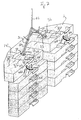
- Fig. 1
- eine Seitenansicht eines Untendreher-Turmdrehkrans mit eingefahrenen Schüssen seines teleskopierbaren Turms während des Ballastierens mit der erfindungsgemäßen Ballastiervorrichtung,
- Fig. 2
- eine perspektivische Ansicht einer an die Lenker der scherenförmigen Kupplungseinrichtung angekuppelten Ballastplatte,
- Fig. 3 bis Fig. 6a
- eine Darstellung der Kupplungsvorrichtung mit den scherenförmigen Lenkern während des Ankuppelns an eine Ballastplatte und
- Fig. 7
- eine vergrößerte Darstellung der Ansicht nach Fig. 2.
Claims (13)
- Vorrichtung zum Ballastieren eines Krans, vorzugsweise eines Untendreher-Turmdrehkrans (1), mit einem Hubseil mit einem Kupplungsteil und mit stapelbaren Ballastplatten (6), die jeweils mit zwei im Abstand voneinander angeordneten Anhängeeinrichtungen zum Anhängen an den Kupplungsteil des Hubseils (12) versehen sind,
dadurch gekennzeichnet, daß das Kupplungsteil aus zwei gelenkig an einem mit dem Hubseil verbundenen Halteteil (23) schwenkbar gelagerten gleich langen Lenkern (20, 21) gebildet ist, die an ihren freien Enden Ösen tragen und mit einer lösbaren, diese spreizenden Spreizeinrichtung (27) versehen sind und
daß die Anhängeeinrichtungen aus Haken (33) zum Einhängen in die Ösen mit nach außen gerichteten Hakenzinken (34) bestehen. - Vorrichtung nach Anspruch 1, dadurch gekennzeichnet, daß an den Lenkern (20, 21) beidseits der Ösen Laufrollen (24) angeordnet sind.
- Vorrichtung nach Anspruch 1 oder 2, dadurch gekennzeichnet, daß die Lenker (20, 21) aus parallel zueinander verlaufenden Streben (30) bestehen, deren freien Enden durch Bolzen zur Bildung der Ösen miteinander verbunden sind.
- Vorrichtung nach einem der Ansprüche 1 bis 3, dadurch gekennzeichnet, daß die verlängerten Enden der Bolzen Achszapfen zur Lagerung der Laufrollen (24) bilden.
- Vorrichtung nach einem der Ansprüche 1 bis 4, dadurch gekennzeichnet, daß die Spreizeinrichtung aus zu einem Kniehebel verbundenen Kniehebellenkern (27) bestehen, deren Enden gelenkig mit den scherenartigen Lenkern (20, 21) verbunden sind, und daß die Lenker (20, 21) mit Anschlägen versehen sind, auf denen sich die Kniehebel (27) nach Verschwenken über ihre gestreckte Totpunktstellung abstützen.
- Vorrichtung nach einem der Ansprüche 1 bis 5, dadurch gekennzeichnet, daß die Kniehebellenker (27) mit mindestens einem über ihre Anlenkungen (25) an den scherenartigen Lenkern (20, 21) hinaus verlängerten Betätigungshebel (28) versehen sind.
- Vorrichtung nach einem der Ansprüche 1 bis 6, dadurch gekennzeichnet, daß die Haken (33) jeweils in Mulden (32) der Ballastplatten (6) angeordnet sind.
- Vorrichtung nach Anspruch 7, dadurch gekennzeichnet, daß jede Mulde (32) mit Führungen für die Enden der Lenker (20, 21) versehen sind.
- Vorrichtung nach Anspruch 7 oder 8, dadurch gekennzeichnet, daß die Mulden (32) parallel zur Verbindungslinie (38) der Haken (33) verlaufende Seiten (35) aufweisen, die Führungen für die Laufrollen (34) bilden.
- Vorrichtung nach einem der Ansprüche 7 bis 9, dadurch gekennzeichnet, daß die Seiten (35) der Mulden (32) in Richtung auf den ebenen Muldengrund (36) hin abgeschrägt sind.
- Vorrichtung nach einem der Ansprüche 7 bis 10, dadurch gekennzeichnet, daß die rechtwinkelig zu der Verbindungslinie (38) der Haken (33) verlaufenden Außenseiten (39) in der Mulden (33) abgeschrägt sind und einen Abstand voneinander aufweisen, der dem Abstand der gespreizten Enden der Lenker (20, 21) entspricht.
- Vorrichtung nach einem der vorhergehenden Ansprüche, dadurch gekennzeichnet, daß die Ballastplatten (6) an ihren Oberseiten mit quer zur Verbindungslinie (38) der Haken (33) verlaufenden, im Querschnitt etwa trapezförmigen Wülsten (40) versehen sind, die in komplementäre Ausnehmungen an den Unterseiten gestapelter Platten (6) eingreifen.
- Vorrichtung nach einem der vorhergehenden Ansprüche, dadurch gekennzeichnet, daß die Ballastplatten (6) Anschlägen oder mit Steigbügeln versehen sind, die die Oberseiten der Ballastplatten (6) überragen und in diese aufnehmende Ausnehmungen (46) an den Seiten zu stapelnder Ballastplatten (6) greifen.
Applications Claiming Priority (2)
| Application Number | Priority Date | Filing Date | Title |
|---|---|---|---|
| DE20019287U DE20019287U1 (de) | 2000-11-14 | 2000-11-14 | Vorrichtung zum Ballastieren eines Krans |
| DE20019287U | 2000-11-14 |
Publications (2)
| Publication Number | Publication Date |
|---|---|
| EP1205422A1 EP1205422A1 (de) | 2002-05-15 |
| EP1205422B1 true EP1205422B1 (de) | 2004-10-27 |
Family
ID=7948775
Family Applications (1)
| Application Number | Title | Priority Date | Filing Date |
|---|---|---|---|
| EP01120276A Expired - Lifetime EP1205422B1 (de) | 2000-11-14 | 2001-08-23 | Vorrichtung zum Ballastieren eines Krans |
Country Status (4)
| Country | Link |
|---|---|
| EP (1) | EP1205422B1 (de) |
| AT (1) | ATE280732T1 (de) |
| DE (2) | DE20019287U1 (de) |
| ES (1) | ES2231363T3 (de) |
Cited By (6)
| Publication number | Priority date | Publication date | Assignee | Title |
|---|---|---|---|---|
| CN103221616A (zh) * | 2010-08-10 | 2013-07-24 | 亚特兰蒂斯能源有限公司 | 水下发电机的支撑设备和部署方法 |
| EP2692682A1 (de) | 2012-07-31 | 2014-02-05 | Manitowoc Crane Group France | Verfahren zum Einbauen und Entfernen von Betonblocks |
| US8960460B2 (en) | 2009-03-09 | 2015-02-24 | Manitowoc Crane Companies, Llc | Counterweight block and assemblies for cranes |
| US8985353B2 (en) | 2006-10-27 | 2015-03-24 | Manitowoc Crane Companies, Llc | Mobile lift crane with variable position counterweight |
| US9278834B2 (en) | 2009-08-06 | 2016-03-08 | Manitowoc Crane Group, LLC | Lift crane with moveable counterweight |
| US12459791B2 (en) | 2023-06-09 | 2025-11-04 | Caterpillar Inc. | Lifting eyes for counterweights |
Families Citing this family (9)
| Publication number | Priority date | Publication date | Assignee | Title |
|---|---|---|---|---|
| FR2854393B1 (fr) * | 2003-04-30 | 2005-06-17 | Potain Sa | Dispositif de lestage pour grue |
| US7546928B2 (en) | 2006-10-27 | 2009-06-16 | Manitowoc Crane Companies, Inc. | Mobile lift crane with variable position counterweight |
| CA2776533A1 (en) | 2009-10-27 | 2011-05-05 | Atlantis Resources Corporation Pte Limited | Underwater power generator |
| KR20140034818A (ko) | 2011-05-10 | 2014-03-20 | 아틀란티스 리소시스 코포레이션 피티이 리미티드 | 수중 발전기를 전개하는 장치 및 방법 |
| US10183848B2 (en) | 2014-01-27 | 2019-01-22 | Manitowoc Crane Companies, Llc | Height adjustment mechanism for an auxiliary member on a crane |
| WO2015113048A1 (en) | 2014-01-27 | 2015-07-30 | Manitowoc Crane Companies, Llc | Lift crane with improved movable counterweight |
| JP6233344B2 (ja) * | 2015-04-02 | 2017-11-22 | コベルコ建機株式会社 | 補助プラットフォーム装置 |
| CN105293312B (zh) * | 2015-11-25 | 2017-09-22 | 镇海建设集团有限公司 | 一种塔式起重机 |
| US10850952B2 (en) * | 2017-07-21 | 2020-12-01 | Brandt Industries Canada Ltd. | Pipelayer with quick attach counterweights |
Family Cites Families (7)
| Publication number | Priority date | Publication date | Assignee | Title |
|---|---|---|---|---|
| FR565173A (de) * | 1923-04-17 | 1924-01-21 | ||
| FR2195971A5 (de) * | 1972-08-07 | 1974-03-08 | Manubat | |
| DE3314051C1 (de) * | 1983-04-19 | 1984-08-16 | Albert 5204 Lohmar Blum | Hebevorrichtung fuer elektrische Tauchpumpeneinheiten |
| DE3611593A1 (de) * | 1986-04-07 | 1987-10-08 | Harnischfeger Gmbh | Verfahren zum selbsttaetigen anhaengen und ablegen eines ausleger-gegengewichtes von hydraulik-fahrzeugkranen und einrichtung zum durchfuehren des verfahrens |
| US4911313A (en) * | 1988-12-09 | 1990-03-27 | Harnischfeger Corporation | Linkage lifting apparatus |
| US5207468A (en) * | 1992-05-27 | 1993-05-04 | Georges Saulnier | Self-adjusting transformer sling |
| DE69321786T2 (de) * | 1992-08-07 | 1999-03-18 | Manitowoc Crane Group, Inc., Reno, Nev. | Fahrzeugkran mit Vorrichtung zum Anbringen des Gegengewichtes |
-
2000
- 2000-11-14 DE DE20019287U patent/DE20019287U1/de not_active Expired - Lifetime
-
2001
- 2001-08-23 AT AT01120276T patent/ATE280732T1/de active
- 2001-08-23 ES ES01120276T patent/ES2231363T3/es not_active Expired - Lifetime
- 2001-08-23 DE DE50104282T patent/DE50104282D1/de not_active Expired - Lifetime
- 2001-08-23 EP EP01120276A patent/EP1205422B1/de not_active Expired - Lifetime
Cited By (6)
| Publication number | Priority date | Publication date | Assignee | Title |
|---|---|---|---|---|
| US8985353B2 (en) | 2006-10-27 | 2015-03-24 | Manitowoc Crane Companies, Llc | Mobile lift crane with variable position counterweight |
| US8960460B2 (en) | 2009-03-09 | 2015-02-24 | Manitowoc Crane Companies, Llc | Counterweight block and assemblies for cranes |
| US9278834B2 (en) | 2009-08-06 | 2016-03-08 | Manitowoc Crane Group, LLC | Lift crane with moveable counterweight |
| CN103221616A (zh) * | 2010-08-10 | 2013-07-24 | 亚特兰蒂斯能源有限公司 | 水下发电机的支撑设备和部署方法 |
| EP2692682A1 (de) | 2012-07-31 | 2014-02-05 | Manitowoc Crane Group France | Verfahren zum Einbauen und Entfernen von Betonblocks |
| US12459791B2 (en) | 2023-06-09 | 2025-11-04 | Caterpillar Inc. | Lifting eyes for counterweights |
Also Published As
| Publication number | Publication date |
|---|---|
| DE20019287U1 (de) | 2002-03-21 |
| ATE280732T1 (de) | 2004-11-15 |
| ES2231363T3 (es) | 2005-05-16 |
| EP1205422A1 (de) | 2002-05-15 |
| DE50104282D1 (de) | 2004-12-02 |
Similar Documents
| Publication | Publication Date | Title |
|---|---|---|
| EP1205422B1 (de) | Vorrichtung zum Ballastieren eines Krans | |
| DE602004000726T2 (de) | Vorrichtung zum Ballastieren eines Krans | |
| DE3446231A1 (de) | Vorrichtung zum verlegen von randsteinen o.dgl. | |
| EP0632171A1 (de) | Faltbare Gerüstbühne | |
| DE10243356A1 (de) | Zerlegbares Gerüst | |
| DE1219649B (de) | Hebeklaue | |
| DE2647227C2 (de) | Umschlaggerät zum Heben und Kippen von Frachtcontainern für Schüttgut | |
| EP3150543A1 (de) | Schrittschaltwerkanordnung für greifereinrichtungen und greifereinrichtung | |
| DE2433871C3 (de) | Absetzkipper zum Aufnehmen, Kippen und Absetzen von Kippmulden, Silos, Paletten o.dgl | |
| DE2217431C3 (de) | Baugerüst | |
| DE2101842B2 (de) | Turmkran | |
| DE3543214A1 (de) | Vorrichtung zum umscheren der durch ein seil mit der laufkatze eines krans verbundenen unterflasche des kranhakens | |
| DE202019107108U1 (de) | Kippvorrichtung für Schwerlasten | |
| DE4137399A1 (de) | Greifvorrichtung fuer rohre | |
| DE29508758U1 (de) | Kran für Hubarbeitsbühne mit Knickauslegearm | |
| DE3249387T1 (de) | Maschine zum Handhaben von Rohren | |
| DE1456491C (de) | Einrichtung zum Transport von Bau schalungen | |
| DE4139909C2 (de) | Aufhängevorrichtung für einen Behälter für Baumaterial, insbesondere für fließfähige Baumaterialien wie Putze, Mörtel u. dgl. | |
| DE4227862C2 (de) | Vorrichtung zur Aufnahme von Gegenständen, insbesondere von Hohl- oder Vollprofilbarren | |
| DE615856C (de) | Gleichzeitig als Riegel dienende Laufbuehne, insbesondere fuer Aufbrueche, mit an den Gleisen angelenkten Schwenkarmen | |
| AT413531B (de) | Anordnung für das heben und transportieren von grossformatigen, insbesondere plattenartigen objekten | |
| DE2101842C (de) | Turmkran | |
| DD266707A3 (de) | Fangvorrichtung fuer schraegaufzuege | |
| DE2335407C3 (de) | Lasttrageinrichtung, insbesondere am Ausleger eines Krans o.dgl. angelenkt | |
| DE9306236U1 (de) | Zange |
Legal Events
| Date | Code | Title | Description |
|---|---|---|---|
| PUAI | Public reference made under article 153(3) epc to a published international application that has entered the european phase |
Free format text: ORIGINAL CODE: 0009012 |
|
| AK | Designated contracting states |
Kind code of ref document: A1 Designated state(s): AT BE CH CY DE DK ES FI FR GB GR IE IT LI LU MC NL PT SE TR |
|
| AX | Request for extension of the european patent |
Free format text: AL;LT;LV;MK;RO;SI |
|
| 17P | Request for examination filed |
Effective date: 20020709 |
|
| AKX | Designation fees paid |
Designated state(s): AT BE CH CY DE DK ES FI FR GB GR IE IT LI LU MC NL PT SE TR |
|
| GRAP | Despatch of communication of intention to grant a patent |
Free format text: ORIGINAL CODE: EPIDOSNIGR1 |
|
| GRAS | Grant fee paid |
Free format text: ORIGINAL CODE: EPIDOSNIGR3 |
|
| GRAA | (expected) grant |
Free format text: ORIGINAL CODE: 0009210 |
|
| AK | Designated contracting states |
Kind code of ref document: B1 Designated state(s): AT BE CH CY DE DK ES FI FR GB GR IE IT LI LU MC NL PT SE TR |
|
| PG25 | Lapsed in a contracting state [announced via postgrant information from national office to epo] |
Ref country code: TR Free format text: LAPSE BECAUSE OF FAILURE TO SUBMIT A TRANSLATION OF THE DESCRIPTION OR TO PAY THE FEE WITHIN THE PRESCRIBED TIME-LIMIT Effective date: 20041027 Ref country code: FI Free format text: LAPSE BECAUSE OF FAILURE TO SUBMIT A TRANSLATION OF THE DESCRIPTION OR TO PAY THE FEE WITHIN THE PRESCRIBED TIME-LIMIT Effective date: 20041027 Ref country code: IE Free format text: LAPSE BECAUSE OF FAILURE TO SUBMIT A TRANSLATION OF THE DESCRIPTION OR TO PAY THE FEE WITHIN THE PRESCRIBED TIME-LIMIT Effective date: 20041027 |
|
| REG | Reference to a national code |
Ref country code: GB Ref legal event code: FG4D Free format text: NOT ENGLISH |
|
| REG | Reference to a national code |
Ref country code: CH Ref legal event code: EP |
|
| REG | Reference to a national code |
Ref country code: IE Ref legal event code: FG4D Free format text: GERMAN |
|
| REF | Corresponds to: |
Ref document number: 50104282 Country of ref document: DE Date of ref document: 20041202 Kind code of ref document: P |
|
| PG25 | Lapsed in a contracting state [announced via postgrant information from national office to epo] |
Ref country code: SE Free format text: LAPSE BECAUSE OF FAILURE TO SUBMIT A TRANSLATION OF THE DESCRIPTION OR TO PAY THE FEE WITHIN THE PRESCRIBED TIME-LIMIT Effective date: 20050127 Ref country code: DK Free format text: LAPSE BECAUSE OF FAILURE TO SUBMIT A TRANSLATION OF THE DESCRIPTION OR TO PAY THE FEE WITHIN THE PRESCRIBED TIME-LIMIT Effective date: 20050127 Ref country code: GR Free format text: LAPSE BECAUSE OF FAILURE TO SUBMIT A TRANSLATION OF THE DESCRIPTION OR TO PAY THE FEE WITHIN THE PRESCRIBED TIME-LIMIT Effective date: 20050127 |
|
| GBT | Gb: translation of ep patent filed (gb section 77(6)(a)/1977) |
Effective date: 20050126 |
|
| REG | Reference to a national code |
Ref country code: ES Ref legal event code: FG2A Ref document number: 2231363 Country of ref document: ES Kind code of ref document: T3 |
|
| REG | Reference to a national code |
Ref country code: IE Ref legal event code: FD4D |
|
| PG25 | Lapsed in a contracting state [announced via postgrant information from national office to epo] |
Ref country code: CY Free format text: LAPSE BECAUSE OF FAILURE TO SUBMIT A TRANSLATION OF THE DESCRIPTION OR TO PAY THE FEE WITHIN THE PRESCRIBED TIME-LIMIT Effective date: 20050823 Ref country code: LU Free format text: LAPSE BECAUSE OF NON-PAYMENT OF DUE FEES Effective date: 20050823 |
|
| ET | Fr: translation filed | ||
| PG25 | Lapsed in a contracting state [announced via postgrant information from national office to epo] |
Ref country code: BE Free format text: LAPSE BECAUSE OF NON-PAYMENT OF DUE FEES Effective date: 20050831 Ref country code: CH Free format text: LAPSE BECAUSE OF NON-PAYMENT OF DUE FEES Effective date: 20050831 Ref country code: MC Free format text: LAPSE BECAUSE OF NON-PAYMENT OF DUE FEES Effective date: 20050831 Ref country code: LI Free format text: LAPSE BECAUSE OF NON-PAYMENT OF DUE FEES Effective date: 20050831 |
|
| PLBE | No opposition filed within time limit |
Free format text: ORIGINAL CODE: 0009261 |
|
| STAA | Information on the status of an ep patent application or granted ep patent |
Free format text: STATUS: NO OPPOSITION FILED WITHIN TIME LIMIT |
|
| 26N | No opposition filed |
Effective date: 20050728 |
|
| REG | Reference to a national code |
Ref country code: CH Ref legal event code: PL |
|
| BERE | Be: lapsed |
Owner name: *LIEBHERR-WERK BIBERACH G.M.B.H. Effective date: 20050831 |
|
| PG25 | Lapsed in a contracting state [announced via postgrant information from national office to epo] |
Ref country code: PT Free format text: LAPSE BECAUSE OF NON-PAYMENT OF DUE FEES Effective date: 20050327 |
|
| REG | Reference to a national code |
Ref country code: FR Ref legal event code: PLFP Year of fee payment: 16 |
|
| REG | Reference to a national code |
Ref country code: FR Ref legal event code: PLFP Year of fee payment: 17 |
|
| REG | Reference to a national code |
Ref country code: FR Ref legal event code: PLFP Year of fee payment: 18 |
|
| PGFP | Annual fee paid to national office [announced via postgrant information from national office to epo] |
Ref country code: NL Payment date: 20200826 Year of fee payment: 20 |
|
| PGFP | Annual fee paid to national office [announced via postgrant information from national office to epo] |
Ref country code: GB Payment date: 20200826 Year of fee payment: 20 Ref country code: FR Payment date: 20200826 Year of fee payment: 20 Ref country code: ES Payment date: 20200902 Year of fee payment: 20 Ref country code: DE Payment date: 20200825 Year of fee payment: 20 |
|
| PGFP | Annual fee paid to national office [announced via postgrant information from national office to epo] |
Ref country code: AT Payment date: 20200824 Year of fee payment: 20 Ref country code: IT Payment date: 20200831 Year of fee payment: 20 |
|
| REG | Reference to a national code |
Ref country code: DE Ref legal event code: R071 Ref document number: 50104282 Country of ref document: DE |
|
| REG | Reference to a national code |
Ref country code: NL Ref legal event code: MK Effective date: 20210822 |
|
| REG | Reference to a national code |
Ref country code: GB Ref legal event code: PE20 Expiry date: 20210822 |
|
| REG | Reference to a national code |
Ref country code: AT Ref legal event code: MK07 Ref document number: 280732 Country of ref document: AT Kind code of ref document: T Effective date: 20210823 |
|
| PG25 | Lapsed in a contracting state [announced via postgrant information from national office to epo] |
Ref country code: GB Free format text: LAPSE BECAUSE OF EXPIRATION OF PROTECTION Effective date: 20210822 |
|
| REG | Reference to a national code |
Ref country code: ES Ref legal event code: FD2A Effective date: 20211130 |
|
| PG25 | Lapsed in a contracting state [announced via postgrant information from national office to epo] |
Ref country code: ES Free format text: LAPSE BECAUSE OF EXPIRATION OF PROTECTION Effective date: 20210824 |