EP1206029A2 - Verbesserter Kühlkörper für einen Wechselrichter eines elektrischen Motors - Google Patents
Verbesserter Kühlkörper für einen Wechselrichter eines elektrischen Motors Download PDFInfo
- Publication number
- EP1206029A2 EP1206029A2 EP01126386A EP01126386A EP1206029A2 EP 1206029 A2 EP1206029 A2 EP 1206029A2 EP 01126386 A EP01126386 A EP 01126386A EP 01126386 A EP01126386 A EP 01126386A EP 1206029 A2 EP1206029 A2 EP 1206029A2
- Authority
- EP
- European Patent Office
- Prior art keywords
- inverter
- heat sink
- sink means
- heat
- heat transfer
- Prior art date
- Legal status (The legal status is an assumption and is not a legal conclusion. Google has not performed a legal analysis and makes no representation as to the accuracy of the status listed.)
- Granted
Links
Images


Classifications
-
- H—ELECTRICITY
- H05—ELECTRIC TECHNIQUES NOT OTHERWISE PROVIDED FOR
- H05K—PRINTED CIRCUITS; CASINGS OR CONSTRUCTIONAL DETAILS OF ELECTRIC APPARATUS; MANUFACTURE OF ASSEMBLAGES OF ELECTRICAL COMPONENTS
- H05K7/00—Constructional details common to different types of electric apparatus
- H05K7/20—Modifications to facilitate cooling, ventilating, or heating
- H05K7/2089—Modifications to facilitate cooling, ventilating, or heating for power electronics, e.g. for inverters for controlling motor
- H05K7/20927—Liquid coolant without phase change
-
- H—ELECTRICITY
- H02—GENERATION; CONVERSION OR DISTRIBUTION OF ELECTRIC POWER
- H02M—APPARATUS FOR CONVERSION BETWEEN AC AND AC, BETWEEN AC AND DC, OR BETWEEN DC AND DC, AND FOR USE WITH MAINS OR SIMILAR POWER SUPPLY SYSTEMS; CONVERSION OF DC OR AC INPUT POWER INTO SURGE OUTPUT POWER; CONTROL OR REGULATION THEREOF
- H02M7/00—Conversion of AC power input into DC power output; Conversion of DC power input into AC power output
- H02M7/003—Constructional details, e.g. physical layout, assembly, wiring or busbar connections
Definitions
- the present invention relates generally to an inverter for an electric traction motor, and more particularly is an improved inverter with a heat sink that utilizes oil (hydraulic fluid) as the heat transfer fluid.
- oil hydroaulic fluid
- Traction vehicles such as locomotives or high power off-road vehicles, are driven by electrically powered traction motors which drive the wheels of the vehicle.
- the traction motors operate on AC power, but the power generated by the motor of the vehicle is DC.
- the DC potential generated by the motor must therefore be converted from DC to AC current in an inverter.
- the electric power generation / inversion requires the use of multiple semiconductor devices, and switches to control the semiconductor devices, all of which generate a great deal of heat.
- To dissipate the heat produced in the inverter current art vehicles use either water or air cooling systems, or both in combination. These current art methods of cooling lead to several problems.
- the inverter comprises a large unit contained in a compartment dedicated only to the inverter. This necessitates that lead wires for control and feedback systems must be fairly long, typically anywhere from 2 to 10 feet. Longer wires are by necessity heavier than shorter wires, both in terms of weight and electrical rating. Longer wires significantly increase the potential for distorted signals.
- an object of the present invention to provide an inverter for an electric traction motor that utilizes the same cooling system used for the motor.
- the present invention is an oil-cooled inverter for an electric traction motor.
- the inverter comprises six IGBT switches to generate 3-phase AC electrical current as its output.
- the switches are mounted on heat sinks that use hot motor oil (hydraulic fluid) as the heat transfer fluid.
- An interior of each of the heat sinks contains a heat transfer medium.
- the heat transfer medium is a plurality of silver plated copper balls. The copper balls are brazed to each other and to the walls of the heat sinks in an assembly process.
- the heat sink housing is made of molybdenum, which has a thermal expansion rate equal to that of silicon.
- the IGBT switch / heat sink assemblies are mounted in a planar fashion in a laminated bus device.
- the bus device also houses a bank of capacitors for the inverter.
- the structure of the bus device allows the IGBT switches and the capacitors of the inverter to be assembled as generally planar elements, thereby reducing inductance of the device. This allows the switches to function more efficiently.
- the inverter of the present invention is in most ways electrically equivalent to prior art inverters.
- One key exception is that the upper surface formed by the bank of heat sinks is electrically hot, and is used as part of the circuitry. This allows the elimination of the insulating plate on which the inverter circuitry is normally mounted, as the chips of the inverter circuitry of the present invention are mounted directly on the upper surface of the heat sinks of the inverter.
- the inverter module of the present invention requires only 10% the amount of space required by the inverter module of the inventors' current art.
- the weight of the inverter module of the present invention is also greatly reduced, being only 20% of that of the current art. This tremendous reduction in size and weight leads to the added benefit of making the inverter module far less expensive and more practical to "spare", that is, to stock an entire inverter module for repair use.
- Another advantage of the present invention is that the reduced size and compact assembly of the inverter allows it to be mounted directly to the motor (generator). This significantly reduces the length of the lead wires of the feedback and control systems.
- a still further advantage of the present invention is that it utilizes the same coolant supply system as does the electric motor of the vehicle, thereby eliminating the necessity of a water cooling system.
- Yet another advantage of the inverter of the present invention is that the chips of the inverter circuitry are mounted directly on the surface of the heat sink, thereby eliminating components and space requirements.
- the surface of the heat sinks is electrically hot, and serves as part of the circuitry.
- Still another advantage of the present invention is that the planar structure reduces inductance in the inverter.
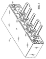
- the present invention is an inverter 10 for an electric traction motor.
- the inverter 10 is cooled with an oil-cooling system.
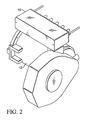
- the inverter 10 is installed in line with the oil-cooling system of the motor 12, so that no additional cooling system is required. Because of the compact design of the inverter 10, the inverter module can be mounted directly to the motor 12.
- Fig. 2 shows the inverter 10 mounted on the generator of the motor 12.
- the inverter 10 comprises an external housing 14 that encloses the components of the inverter 10.
- the current output by the inverter 10 is accessed at multiple output terminals 16 which protrude from a front side of the inverter housing 10.
- the current output by the inverter 10 serves as the power source to drive the traction wheels of the vehicle.
- the cooling fluid hot oil from the motor 12, enters the inverter 10 through a coolant inlet port 18, and exits via a coolant outlet port 20.
- the oil flows through the heat sinks 22, which each have an IGBT switch 24 mounted on a top surface thereof.
- IGBT switch 24 mounted on a top surface thereof.
- the six IGBT switches 24 are necessary to enable the inverter 10 to provide 3-phase AC current as its output.
- a capacitor bank 28 is included in the inverter to provide a storage mechanism that provides a pulsing means for the inverter 10.
- the capacitor bank 28 comprises a plurality of capacitors 281 fixed side by side.
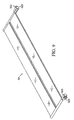
- the IGBT switch / heat sink assemblies 26 and the capacitor bank 28 are mounted on a laminated bus device 30, illustrated in Figs. 5-7.
- the bus device 30 comprises a planar central body 301 secured between two end plates 302.
- the six IGBT switch / heat sink assemblies 26 are mounted on an upper surface of the central body 301 of the bus device 30.
- the capacitor bank 28 is mounted on a rear side of a lower surface of the central body 301 of the bus 30.
- the capacitor bank 28, as shown in Fig. 8, comprises a plurality of capacitors 281 fixed side by side in mounting brackets 282.
- a capacitor cold plate 32 is sandwiched between the capacitor bank 28 and the bus 30 to remove heat from the capacitor bank 28.
- the capacitor cold plate 32 like the heat sinks 22, utilizes coolant (oil) from the motor of the vehicle.
- a coolant inlet port 322 and a coolant outlet port 323 are provided on the cold plate 32.
- the front side of the lower surface of the central body 301 serves as a mounting means for a plurality of output brackets 34.
- the output brackets 34 are simply heavy, electrically conductive elements that serve to convey the current produced from the inverter 10 to the output terminals 16. Lead wires from the traction wheels of the vehicle are then affixed to the output terminals 16.
- a contact bar extending upward from a first side of the central body 301 comprises an upper portion of a positive bus 303.
- the positive bus 303 also extends downward behind the central body 301 to provide a contact area for the capacitor bank 28.
- a plurality of raised contact bars extending upward from the front side of the central body 301 comprise a negative bus 304.
- a plurality of raised contact bars in a center portion of the central body 301 comprise an output connecter bus 305.
- the raised portions of bus strips 303, 304, 305 form a pair of longitudinal mounting channels. Each of the channels is used to securely mount three IGBT switch / heat sink assemblies 26, so that the six IGBT switch / heat sink assemblies 26 are aligned in two rows.
- the positive bus 303 and the output connecter bus 305 form a first channel 306 that contains a first row of three IGBT switch / heat sink assemblies 261, 262, 263.
- the negative bus 304 and the output connecter bus 305 form a second channel 307 that contains a second row of three IGBT switch / heat sink assemblies 26.
- the first row of the IGBT switches 24 activates the positive segment, in 120° intervals, of the AC current generated.
- the second row of IGBT switches 24 activates the negative segment, also in 120° intervals, of the AC current.
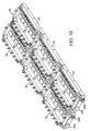
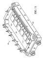
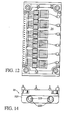
- Fig. 10 shows the two rows of IGBT switch / heat sink assemblies 26 assembled on their respective heat sinks 22. It should be noted that the structure of the bus device 30 allows the IGBT switch / heat sink assemblies 26 and the capacitor bank 28 to be assembled as generally flat, planar elements. This construction reduces the inductance present in the inverter 10, thereby allowing the IGBT switches 24 to operate more rapidly, which improves the overall performance of the inverter 10.
- the inverter of the present invention is in most ways electrically equivalent to prior art inverters.
- One key exception is that the upper surface formed by the bank of heat sinks is electrically hot, and is used as part of the circuitry. This allows the elimination of the insulating plate on which the inverter circuitry is normally mounted, as the chips of the inverter circuitry of the present invention are mounted directly on the upper surface of the heat sinks of the inverter.
- the inverter of the present invention uses as its input a 600 volt DC potential generated by the motor.
- the output of the inverter of the present invention is 600 amp AC current.
- the IGBT switches 24 are mounted directly on an upper surface of the heat sinks 22.
- the upper surface of the heat sinks 22 is electrically hot, and serves as part of the inverter circuitry.
- the heat sink housing 221 is formed from nickel plated molybdenum, which has the same coefficient of thermal expansion as silicon. This means that the silicon substrate of the chips of the inverter circuitry will expand and contract at the same rate as the heat sink housing as the inverter heats and cools.
- the heat sinks 22 include a pair of parallel coolant throughways 222 in their interiors.
- the throughways 222 each include an open section 223 on an upper inner side thereof. This allows a heat transfer fluid flowing in a first throughway 222 to spill over into the interior of the housing 221, and engulf a heat transfer medium 224. The fluid fills the interior of the heat sink 22, and flows into the open section 223 of the second throughway 222.
- the heat transfer fluid enters the inverter 10 from the coolant supply port 18 through an upper supply side inlet port 225 on the heat sink 22 of the first in line IGBT switch / heat sink assemblies 261 of each of the rows of assemblies 26.
- the second supply side inlet port 226 of the first in line heat sinks are capped.
- the throughways 222 of the first in line heat sinks are connected to the throughways 222 of the second in line heat sinks, which are in turn connected to the throughways of the third in line heat sinks.
- the connections of the throughways are accomplished by using known rubber connectors.
- the lower throughway openings of the third in line heat sinks are open, and the upper openings are capped.
- the heat transfer fluid thus enters each row of heat sinks from an upper inlet side, flows through the row, and flows out of the third in line heat sinks at a lower outlet side.
- heat transfer fluid flows through and around the heat transfer medium 224, heat conveyed into the heat transfer medium 224 from the IGBT switches 22 is removed by the heat transfer fluid.
- the heat transfer fluid is motor oil
- the heat transfer medium 224 is a plurality of silver plated copper balls.
- the copper balls 224 are brazed to each other and to the walls of the heat sinks 22 in a unique assembly process.
- the spherical shape of the balls provides an excellent means of creating contact from each ball 224 with a plurality of other balls 224 and with the interior walls of the heat sink housing 221. This creates a superior heat transfer path in the heat sinks 22.
- the flow paths created between the balls 224 have smooth boundaries and are relatively large. Free flow through the heat transfer medium is critical so that debris from the motor oil does not become trapped in the interior of the housing 221.
- the heat sinks 22 are formed as follows: Approximately 3/32" diameter balls 224 are packed together in the interior of the heat sink housing. The balls 224 have to be bonded to each other and to the manifold with a maximum bond contact area in order to allow for optimal heat conduction.
- the metallurgical bonding between the balls 224 is achieved by first plating a brazing compound on the balls. The key consideration in the plating process is to provide a sufficient plating layer so that during a brazing cycle, a sufficient volume of liquified material is produced to provide wetting at contact points between the balls to increase the size of the conductive heat transfer paths.
- a copper ball 224 is used. Because copper alloys are susceptible to hydrogen embrittlement, the composition of the balls must be controlled to allow for the thermal processing required during the brazing process. In the preferred embodiment, an OFHC (Oxygen Free High Conductivity) copper alloy ball is utilized.
- the alloy must be free of contaminants to be properly bonded in the brazing process. For this reason, the commercially available copper balls are first chemical milled to remove a significant amount of material from the surface of the balls. The degree of material removal necessary is defined by the condition of the balls as purchased.
- a copper-silver eutectic brazing compound is used to bond the balls together.
- the eutectic copper-silver alloy is produced by first plating silver onto the copper balls, and then thermally processing the resultant matrix to achieve the proper amount of liquification.
- the balls are prepared by electrodepositing a 0.5 mil thick layer of dull silver onto the copper balls.
- the balls After the balls have been silver plated, they are introduced into the interior of the heat sink housing. The housing is then secured in a brazing fixture. With an appropriate fixture, the brazing of the individual elements of the porous metal heat transfer medium and the securing of the manifolds to the heat sink housing can be performed concurrently. The following thermal cycling is used during the brazing process:
- the resultant heat sink is then ready for installation on the inverter.
- one surface of the heat sink is used as a mounting area for the inverter circuitry, that surface must be relatively flat. Occasionally during the brazing process, the bonding of the balls to the wall of the housing causes excessive deformation of the housing. The amount of acceptable variance from flat will vary according to the specific application. If the brazing process takes the surface of the heat sink outside acceptable tolerances, additional processing is required.
- the flatness of the heat sink wall can be restored by resurfacing and re-plating the wall. It has also been discovered that the flattening of the wall can be accomplished by a coining process.
- the coining process simply involves applying high pressure to the housing (a cold forming process) until the surface is brought within acceptable flatness limits.
Landscapes
- Engineering & Computer Science (AREA)
- Microelectronics & Electronic Packaging (AREA)
- Physics & Mathematics (AREA)
- Thermal Sciences (AREA)
- Power Engineering (AREA)
- Inverter Devices (AREA)
- Cooling Or The Like Of Semiconductors Or Solid State Devices (AREA)
- Motor Or Generator Cooling System (AREA)
Applications Claiming Priority (2)
| Application Number | Priority Date | Filing Date | Title |
|---|---|---|---|
| US708182 | 2000-11-07 | ||
| US09/708,182 US6529394B1 (en) | 2000-11-07 | 2000-11-07 | Inverter for an electric motor |
Publications (3)
| Publication Number | Publication Date |
|---|---|
| EP1206029A2 true EP1206029A2 (de) | 2002-05-15 |
| EP1206029A3 EP1206029A3 (de) | 2004-01-02 |
| EP1206029B1 EP1206029B1 (de) | 2006-12-27 |
Family
ID=24844716
Family Applications (1)
| Application Number | Title | Priority Date | Filing Date |
|---|---|---|---|
| EP01126386A Expired - Lifetime EP1206029B1 (de) | 2000-11-07 | 2001-11-07 | Verbesserter Kühlkörper für einen Wechselrichter eines elektrischen Motors |
Country Status (5)
| Country | Link |
|---|---|
| US (1) | US6529394B1 (de) |
| EP (1) | EP1206029B1 (de) |
| AT (1) | ATE349801T1 (de) |
| DE (1) | DE60125493T2 (de) |
| ES (1) | ES2276739T3 (de) |
Cited By (18)
| Publication number | Priority date | Publication date | Assignee | Title |
|---|---|---|---|---|
| WO2003063567A1 (en) | 2002-01-16 | 2003-07-31 | Rockwell Automation Technologies, Inc. | Modular power converter having fluid cooled support |
| US7032695B2 (en) | 2002-01-16 | 2006-04-25 | Rockwell Automation Technologies, Inc. | Vehicle drive module having improved terminal design |
| WO2006045837A1 (de) * | 2004-10-27 | 2006-05-04 | Robert Bosch Gmbh | Elektrische schaltungseinheit |
| US7095612B2 (en) | 2002-01-16 | 2006-08-22 | Rockwell Automation Technologies, Inc. | Cooled electrical terminal assembly and device incorporating same |
| US7142434B2 (en) | 2002-01-16 | 2006-11-28 | Rockwell Automation Technologies, Inc. | Vehicle drive module having improved EMI shielding |
| US7177153B2 (en) | 2002-01-16 | 2007-02-13 | Rockwell Automation Technologies, Inc. | Vehicle drive module having improved cooling configuration |
| US7187548B2 (en) | 2002-01-16 | 2007-03-06 | Rockwell Automation Technologies, Inc. | Power converter having improved fluid cooling |
| US7187568B2 (en) | 2002-01-16 | 2007-03-06 | Rockwell Automation Technologies, Inc. | Power converter having improved terminal structure |
| EP1603694A4 (de) * | 2003-03-04 | 2008-10-22 | United Defense Lp | Elektrischer bus mit entsprechendem kühlkörper aus porösem material und verfahren zu dessen herstellung |
| US7450388B2 (en) | 2002-01-16 | 2008-11-11 | Rockwell Automation Technologies, Inc. | Power converter connection configuration |
| WO2008113332A3 (de) * | 2007-03-20 | 2009-01-29 | Conti Temic Microelectronic | Steuergerät zum einsatz im motorraum oder im getriebe eines kraftfahrzeugs sowie kühlanordnung für ein derartiges steuergerät |
| WO2017136788A1 (en) * | 2016-02-03 | 2017-08-10 | Faraday & Future Inc. | Inverter assembly |
| US9743563B2 (en) | 2007-03-20 | 2017-08-22 | Conti Temic Microelectronic Gmbh | Control appliance for using in the engine compartment or in the transmission of a motor vehicle and cooling system for such a control appliance |
| DE102017204112A1 (de) | 2017-03-13 | 2018-09-13 | Zf Friedrichshafen Ag | Wechselrichteranordnung und Verfahren zum Herstellen einer Wechselrichteranordnung |
| US10135355B2 (en) | 2015-08-31 | 2018-11-20 | Faraday&Future Inc. | Inverter DC bus bar assembly |
| US10326378B2 (en) | 2015-08-31 | 2019-06-18 | Faraday & Future Inc. | Inverter assembly |
| US11218080B2 (en) | 2015-08-31 | 2022-01-04 | Faraday & Future Inc. | Inverter AC bus bar assembly |
| WO2025193392A1 (en) * | 2024-03-12 | 2025-09-18 | Caterpillar Inc. | Power electronics module with integrated heat sink |
Families Citing this family (34)
| Publication number | Priority date | Publication date | Assignee | Title |
|---|---|---|---|---|
| US7679234B1 (en) * | 2000-09-22 | 2010-03-16 | Isothermal Systems Research, Inc. | Spray cool means for cooling a modular inverter electric motor system |
| US7180100B2 (en) * | 2001-03-27 | 2007-02-20 | Ricoh Company, Ltd. | Semiconductor light-emitting device, surface-emission laser diode, and production apparatus thereof, production method, optical module and optical telecommunication system |
| JP3676719B2 (ja) * | 2001-10-09 | 2005-07-27 | 株式会社日立製作所 | 水冷インバータ |
| US6965514B2 (en) * | 2002-01-16 | 2005-11-15 | Rockwell Automation Technologies, Inc. | Fluid cooled vehicle drive module |
| US6982873B2 (en) * | 2002-01-16 | 2006-01-03 | Rockwell Automation Technologies, Inc. | Compact vehicle drive module having improved thermal control |
| DE10227008B4 (de) * | 2002-06-18 | 2012-10-18 | Robert Bosch Gmbh | Kühlvorrichtung für Halbleitermodule und Elektronikanordnung |
| US7068507B2 (en) * | 2002-09-27 | 2006-06-27 | Rockwell Automation Technologies, Inc. | Compact liquid converter assembly |
| US6822850B2 (en) * | 2002-09-27 | 2004-11-23 | Rockwell Automation Technologies, Inc. | Laminated bus bar for use with a power conversion configuration |
| US6721181B1 (en) * | 2002-09-27 | 2004-04-13 | Rockwell Automation Technologies, Inc. | Elongated heat sink for use in converter assemblies |
| US6956742B2 (en) * | 2002-09-27 | 2005-10-18 | Rockwell Automation Technologies, Inc. | Compact liquid converter assembly |
| US6885553B2 (en) * | 2002-09-27 | 2005-04-26 | Rockwell Automation Technologies, Inc. | Bus bar assembly for use with a compact power conversion assembly |
| JP4055003B2 (ja) * | 2003-09-04 | 2008-03-05 | アイシン・エィ・ダブリュ株式会社 | 車両を駆動するモータの制御装置 |
| US7327024B2 (en) * | 2004-11-24 | 2008-02-05 | General Electric Company | Power module, and phase leg assembly |
| US7353859B2 (en) * | 2004-11-24 | 2008-04-08 | General Electric Company | Heat sink with microchannel cooling for power devices |
| US7427566B2 (en) * | 2005-12-09 | 2008-09-23 | General Electric Company | Method of making an electronic device cooling system |
| US20070131659A1 (en) * | 2005-12-09 | 2007-06-14 | Durocher Kevin M | Method of making an electronic device cooling system |
| JP2007189865A (ja) * | 2006-01-16 | 2007-07-26 | Mitsubishi Electric Corp | 制御装置一体型回転電機 |
| EP2180776B1 (de) * | 2008-10-24 | 2011-04-27 | C.R.F. Società Consortile Per Azioni | Kraftfahrzeugwechselrichtereinheit |
| US8310831B2 (en) | 2010-05-19 | 2012-11-13 | Hamilton Sundstrand Corporation | Thermal packaging of a motor controller for an auxiliary power unit |
| US9030822B2 (en) | 2011-08-15 | 2015-05-12 | Lear Corporation | Power module cooling system |
| US9076593B2 (en) | 2011-12-29 | 2015-07-07 | Lear Corporation | Heat conductor for use with an inverter in an electric vehicle (EV) or a hybrid-electric vehicle (HEV) |
| US8811015B2 (en) | 2012-02-16 | 2014-08-19 | Mission Motor Company | Motor control device |
| WO2013122594A1 (en) * | 2012-02-16 | 2013-08-22 | Mission Motors | Motor control device |
| US8971041B2 (en) | 2012-03-29 | 2015-03-03 | Lear Corporation | Coldplate for use with an inverter in an electric vehicle (EV) or a hybrid-electric vehicle (HEV) |
| US8902582B2 (en) | 2012-05-22 | 2014-12-02 | Lear Corporation | Coldplate for use with a transformer in an electric vehicle (EV) or a hybrid-electric vehicle (HEV) |
| US8971038B2 (en) | 2012-05-22 | 2015-03-03 | Lear Corporation | Coldplate for use in an electric vehicle (EV) or a hybrid-electric vehicle (HEV) |
| US8995133B2 (en) * | 2012-10-31 | 2015-03-31 | Deere & Company | Electrical connection assembly |
| DE102013222148A1 (de) | 2012-11-27 | 2014-05-28 | Lear Corp. | Kälteplatte für die Verwendung in einem Elektro- oder Hybridfahrzeug |
| US9362040B2 (en) | 2014-05-15 | 2016-06-07 | Lear Corporation | Coldplate with integrated electrical components for cooling thereof |
| US9615490B2 (en) | 2014-05-15 | 2017-04-04 | Lear Corporation | Coldplate with integrated DC link capacitor for cooling thereof |
| US10850623B2 (en) * | 2017-10-30 | 2020-12-01 | Sf Motors, Inc. | Stacked electric vehicle inverter cells |
| US10690422B2 (en) | 2018-08-03 | 2020-06-23 | General Electric Company | Thermal management system |
| DE102019125733B4 (de) * | 2019-09-25 | 2021-10-07 | Audi Ag | Gemoldetes Leistungsmodul mit integrierter Erregerschaltung |
| DE102022208365A1 (de) | 2022-08-11 | 2023-07-27 | Zf Friedrichshafen Ag | Kraftfahrzeug |
Family Cites Families (10)
| Publication number | Priority date | Publication date | Assignee | Title |
|---|---|---|---|---|
| US4730665A (en) * | 1983-07-14 | 1988-03-15 | Technology Enterprises Company | Apparatus for cooling high-density integrated circuit packages |
| US4754607A (en) * | 1986-12-12 | 1988-07-05 | Allied-Signal Inc. | Power generating system |
| US5184291A (en) * | 1991-06-13 | 1993-02-02 | Crowe Lawrence E | Converter and inverter support module |
| JPH07194139A (ja) * | 1993-12-27 | 1995-07-28 | Hitachi Ltd | 電気自動車用インバータの冷却装置 |
| WO1995034438A1 (en) * | 1994-06-10 | 1995-12-21 | Westinghouse Electric Corporation | Electrical vehicle propulsion system |
| JP3327317B2 (ja) * | 1995-10-09 | 2002-09-24 | 株式会社荏原製作所 | インバータの水冷方法 |
| FR2756134B1 (fr) * | 1996-11-21 | 1999-07-09 | Gec Alsthom Transport Sa | Dispositif de refroidissement pour composants igbt |
| JP3695023B2 (ja) * | 1996-11-27 | 2005-09-14 | 日産自動車株式会社 | 電気自動車の過負荷防止装置 |
| JPH11346480A (ja) * | 1998-06-02 | 1999-12-14 | Hitachi Ltd | インバータ装置 |
| US6118238A (en) * | 1998-08-26 | 2000-09-12 | Satcon Technology Corporation | Motor starting apparatus for an engine driven generator |
-
2000
- 2000-11-07 US US09/708,182 patent/US6529394B1/en not_active Expired - Fee Related
-
2001
- 2001-11-07 EP EP01126386A patent/EP1206029B1/de not_active Expired - Lifetime
- 2001-11-07 ES ES01126386T patent/ES2276739T3/es not_active Expired - Lifetime
- 2001-11-07 AT AT01126386T patent/ATE349801T1/de not_active IP Right Cessation
- 2001-11-07 DE DE60125493T patent/DE60125493T2/de not_active Expired - Lifetime
Cited By (22)
| Publication number | Priority date | Publication date | Assignee | Title |
|---|---|---|---|---|
| US7450388B2 (en) | 2002-01-16 | 2008-11-11 | Rockwell Automation Technologies, Inc. | Power converter connection configuration |
| US6940715B2 (en) | 2002-01-16 | 2005-09-06 | Rockwell Automation Technologies, Inc. | Modular power converter having fluid cooled support |
| US6972957B2 (en) | 2002-01-16 | 2005-12-06 | Rockwell Automation Technologies, Inc. | Modular power converter having fluid cooled support |
| US7016192B2 (en) | 2002-01-16 | 2006-03-21 | Rockwell Automation Technologies, Inc. | Electrical power converter method and system employing multiple-output converters |
| US7032695B2 (en) | 2002-01-16 | 2006-04-25 | Rockwell Automation Technologies, Inc. | Vehicle drive module having improved terminal design |
| WO2003063567A1 (en) | 2002-01-16 | 2003-07-31 | Rockwell Automation Technologies, Inc. | Modular power converter having fluid cooled support |
| US7095612B2 (en) | 2002-01-16 | 2006-08-22 | Rockwell Automation Technologies, Inc. | Cooled electrical terminal assembly and device incorporating same |
| US7142434B2 (en) | 2002-01-16 | 2006-11-28 | Rockwell Automation Technologies, Inc. | Vehicle drive module having improved EMI shielding |
| US7177153B2 (en) | 2002-01-16 | 2007-02-13 | Rockwell Automation Technologies, Inc. | Vehicle drive module having improved cooling configuration |
| US7187548B2 (en) | 2002-01-16 | 2007-03-06 | Rockwell Automation Technologies, Inc. | Power converter having improved fluid cooling |
| US7187568B2 (en) | 2002-01-16 | 2007-03-06 | Rockwell Automation Technologies, Inc. | Power converter having improved terminal structure |
| US7212407B2 (en) | 2002-01-16 | 2007-05-01 | Rockwell Automation Technologies, Inc. | Electrical power converter method and system employing multiple output converters |
| EP1603694A4 (de) * | 2003-03-04 | 2008-10-22 | United Defense Lp | Elektrischer bus mit entsprechendem kühlkörper aus porösem material und verfahren zu dessen herstellung |
| WO2006045837A1 (de) * | 2004-10-27 | 2006-05-04 | Robert Bosch Gmbh | Elektrische schaltungseinheit |
| WO2008113332A3 (de) * | 2007-03-20 | 2009-01-29 | Conti Temic Microelectronic | Steuergerät zum einsatz im motorraum oder im getriebe eines kraftfahrzeugs sowie kühlanordnung für ein derartiges steuergerät |
| US9743563B2 (en) | 2007-03-20 | 2017-08-22 | Conti Temic Microelectronic Gmbh | Control appliance for using in the engine compartment or in the transmission of a motor vehicle and cooling system for such a control appliance |
| US10135355B2 (en) | 2015-08-31 | 2018-11-20 | Faraday&Future Inc. | Inverter DC bus bar assembly |
| US10326378B2 (en) | 2015-08-31 | 2019-06-18 | Faraday & Future Inc. | Inverter assembly |
| US11218080B2 (en) | 2015-08-31 | 2022-01-04 | Faraday & Future Inc. | Inverter AC bus bar assembly |
| WO2017136788A1 (en) * | 2016-02-03 | 2017-08-10 | Faraday & Future Inc. | Inverter assembly |
| DE102017204112A1 (de) | 2017-03-13 | 2018-09-13 | Zf Friedrichshafen Ag | Wechselrichteranordnung und Verfahren zum Herstellen einer Wechselrichteranordnung |
| WO2025193392A1 (en) * | 2024-03-12 | 2025-09-18 | Caterpillar Inc. | Power electronics module with integrated heat sink |
Also Published As
| Publication number | Publication date |
|---|---|
| US6529394B1 (en) | 2003-03-04 |
| DE60125493T2 (de) | 2007-06-21 |
| ES2276739T3 (es) | 2007-07-01 |
| EP1206029A3 (de) | 2004-01-02 |
| ATE349801T1 (de) | 2007-01-15 |
| DE60125493D1 (de) | 2007-02-08 |
| EP1206029B1 (de) | 2006-12-27 |
Similar Documents
| Publication | Publication Date | Title |
|---|---|---|
| US6529394B1 (en) | Inverter for an electric motor | |
| US6678182B2 (en) | Electrical bus with associated porous metal heat sink and method of manufacturing same | |
| AU2004216692B2 (en) | Electrical bus with associated porous metal heat sink and method of manufacturing same | |
| CN1114339C (zh) | 用于大功率半导体模件的液体冷却装置 | |
| US6016007A (en) | Power electronics cooling apparatus | |
| CN101533833B (zh) | 具有集成冷却的汇流条组件 | |
| CN101174799B (zh) | 电力转换装置 | |
| WO2006103721A1 (ja) | 電力変換装置の冷却構造 | |
| CN107305888B (zh) | 半导体模块 | |
| CN101901638A (zh) | 具有集成冷却装置的堆叠汇流排组件 | |
| JPH07507438A (ja) | 半導体スイッチを有する電気機械 | |
| JPWO2015111211A1 (ja) | パワーモジュール及びその製造方法 | |
| JP7603746B2 (ja) | 冷却装置を有するパルスインバータ、及びパルスインバータを有する自動車 | |
| JP2013093343A (ja) | 半導体装置 | |
| CN117981482A (zh) | 功率模块、特别是用于车辆的功率电子器件的功率模块 | |
| EP1162662A2 (de) | Busschiene mit eingebautem Schaltteil | |
| US6347452B1 (en) | Method of manufacturing a porous metal heat sink | |
| KR20240062178A (ko) | 파워 모듈 및 그 제조 방법 | |
| CN222966902U (zh) | 功率模块及电控制器 | |
| JP3250504U (ja) | パワーデバイスおよびパワーデバイスの組立方法 | |
| CN120092322A (zh) | 具有电子元件的系统 | |
| CN120199738A (zh) | 一种高功率密度的水冷散热双面功率模块系统及使用方法 | |
| KR20070067065A (ko) | 전력 변환 장치의 냉각 구조 | |
| JP2006128259A (ja) | 半導体装置および冷却器付半導体装置 |
Legal Events
| Date | Code | Title | Description |
|---|---|---|---|
| PUAI | Public reference made under article 153(3) epc to a published international application that has entered the european phase |
Free format text: ORIGINAL CODE: 0009012 |
|
| AK | Designated contracting states |
Kind code of ref document: A2 Designated state(s): AT BE CH CY DE DK ES FI FR GB GR IE IT LI LU MC NL PT SE TR |
|
| AX | Request for extension of the european patent |
Free format text: AL;LT;LV;MK;RO;SI |
|
| PUAL | Search report despatched |
Free format text: ORIGINAL CODE: 0009013 |
|
| AK | Designated contracting states |
Kind code of ref document: A3 Designated state(s): AT BE CH CY DE DK ES FI FR GB GR IE IT LI LU MC NL PT SE TR |
|
| AX | Request for extension of the european patent |
Extension state: AL LT LV MK RO SI |
|
| RIC1 | Information provided on ipc code assigned before grant |
Ipc: 7H 05K 7/20 B Ipc: 7H 05K 7/14 B Ipc: 7H 02M 7/515 A |
|
| 17P | Request for examination filed |
Effective date: 20040630 |
|
| AKX | Designation fees paid |
Designated state(s): AT BE CH CY DE DK ES FI FR GB GR IE IT LI LU MC NL PT SE TR |
|
| 17Q | First examination report despatched |
Effective date: 20041005 |
|
| GRAP | Despatch of communication of intention to grant a patent |
Free format text: ORIGINAL CODE: EPIDOSNIGR1 |
|
| GRAS | Grant fee paid |
Free format text: ORIGINAL CODE: EPIDOSNIGR3 |
|
| GRAA | (expected) grant |
Free format text: ORIGINAL CODE: 0009210 |
|
| RAP1 | Party data changed (applicant data changed or rights of an application transferred) |
Owner name: BAE SYSTEMS LAND & ARMAMENTS, L.P. |
|
| AK | Designated contracting states |
Kind code of ref document: B1 Designated state(s): AT BE CH CY DE DK ES FI FR GB GR IE IT LI LU MC NL PT SE TR |
|
| PG25 | Lapsed in a contracting state [announced via postgrant information from national office to epo] |
Ref country code: DK Free format text: LAPSE BECAUSE OF FAILURE TO SUBMIT A TRANSLATION OF THE DESCRIPTION OR TO PAY THE FEE WITHIN THE PRESCRIBED TIME-LIMIT Effective date: 20061227 Ref country code: BE Free format text: LAPSE BECAUSE OF FAILURE TO SUBMIT A TRANSLATION OF THE DESCRIPTION OR TO PAY THE FEE WITHIN THE PRESCRIBED TIME-LIMIT Effective date: 20061227 |
|
| REG | Reference to a national code |
Ref country code: GB Ref legal event code: FG4D |
|
| REG | Reference to a national code |
Ref country code: IE Ref legal event code: FG4D |
|
| REF | Corresponds to: |
Ref document number: 60125493 Country of ref document: DE Date of ref document: 20070208 Kind code of ref document: P |
|
| REG | Reference to a national code |
Ref country code: CH Ref legal event code: NV Representative=s name: KELLER & PARTNER PATENTANWAELTE AG WINTERTHUR |
|
| REG | Reference to a national code |
Ref country code: SE Ref legal event code: TRGR |
|
| PG25 | Lapsed in a contracting state [announced via postgrant information from national office to epo] |
Ref country code: PT Free format text: LAPSE BECAUSE OF FAILURE TO SUBMIT A TRANSLATION OF THE DESCRIPTION OR TO PAY THE FEE WITHIN THE PRESCRIBED TIME-LIMIT Effective date: 20070528 |
|
| REG | Reference to a national code |
Ref country code: ES Ref legal event code: FG2A Ref document number: 2276739 Country of ref document: ES Kind code of ref document: T3 |
|
| EN | Fr: translation not filed | ||
| PLBE | No opposition filed within time limit |
Free format text: ORIGINAL CODE: 0009261 |
|
| STAA | Information on the status of an ep patent application or granted ep patent |
Free format text: STATUS: NO OPPOSITION FILED WITHIN TIME LIMIT |
|
| 26N | No opposition filed |
Effective date: 20070928 |
|
| PG25 | Lapsed in a contracting state [announced via postgrant information from national office to epo] |
Ref country code: GR Free format text: LAPSE BECAUSE OF FAILURE TO SUBMIT A TRANSLATION OF THE DESCRIPTION OR TO PAY THE FEE WITHIN THE PRESCRIBED TIME-LIMIT Effective date: 20070328 Ref country code: FR Free format text: LAPSE BECAUSE OF FAILURE TO SUBMIT A TRANSLATION OF THE DESCRIPTION OR TO PAY THE FEE WITHIN THE PRESCRIBED TIME-LIMIT Effective date: 20070817 |
|
| PG25 | Lapsed in a contracting state [announced via postgrant information from national office to epo] |
Ref country code: MC Free format text: LAPSE BECAUSE OF NON-PAYMENT OF DUE FEES Effective date: 20071130 |
|
| EUG | Se: european patent has lapsed | ||
| GBPC | Gb: european patent ceased through non-payment of renewal fee |
Effective date: 20071107 |
|
| PG25 | Lapsed in a contracting state [announced via postgrant information from national office to epo] |
Ref country code: LI Free format text: LAPSE BECAUSE OF NON-PAYMENT OF DUE FEES Effective date: 20071130 Ref country code: CH Free format text: LAPSE BECAUSE OF NON-PAYMENT OF DUE FEES Effective date: 20071130 |
|
| REG | Reference to a national code |
Ref country code: CH Ref legal event code: PL |
|
| PG25 | Lapsed in a contracting state [announced via postgrant information from national office to epo] |
Ref country code: SE Free format text: LAPSE BECAUSE OF NON-PAYMENT OF DUE FEES Effective date: 20071108 Ref country code: IE Free format text: LAPSE BECAUSE OF NON-PAYMENT OF DUE FEES Effective date: 20071107 |
|
| PG25 | Lapsed in a contracting state [announced via postgrant information from national office to epo] |
Ref country code: FR Free format text: LAPSE BECAUSE OF FAILURE TO SUBMIT A TRANSLATION OF THE DESCRIPTION OR TO PAY THE FEE WITHIN THE PRESCRIBED TIME-LIMIT Effective date: 20061227 |
|
| PG25 | Lapsed in a contracting state [announced via postgrant information from national office to epo] |
Ref country code: GB Free format text: LAPSE BECAUSE OF NON-PAYMENT OF DUE FEES Effective date: 20071107 |
|
| PG25 | Lapsed in a contracting state [announced via postgrant information from national office to epo] |
Ref country code: AT Free format text: LAPSE BECAUSE OF NON-PAYMENT OF DUE FEES Effective date: 20071107 |
|
| PG25 | Lapsed in a contracting state [announced via postgrant information from national office to epo] |
Ref country code: CY Free format text: LAPSE BECAUSE OF FAILURE TO SUBMIT A TRANSLATION OF THE DESCRIPTION OR TO PAY THE FEE WITHIN THE PRESCRIBED TIME-LIMIT Effective date: 20061227 Ref country code: LU Free format text: LAPSE BECAUSE OF NON-PAYMENT OF DUE FEES Effective date: 20071107 |
|
| PG25 | Lapsed in a contracting state [announced via postgrant information from national office to epo] |
Ref country code: TR Free format text: LAPSE BECAUSE OF FAILURE TO SUBMIT A TRANSLATION OF THE DESCRIPTION OR TO PAY THE FEE WITHIN THE PRESCRIBED TIME-LIMIT Effective date: 20061227 |
|
| PGFP | Annual fee paid to national office [announced via postgrant information from national office to epo] |
Ref country code: IT Payment date: 20101123 Year of fee payment: 10 |
|
| PGFP | Annual fee paid to national office [announced via postgrant information from national office to epo] |
Ref country code: ES Payment date: 20111124 Year of fee payment: 11 Ref country code: FI Payment date: 20111125 Year of fee payment: 11 Ref country code: NL Payment date: 20111129 Year of fee payment: 11 |
|
| REG | Reference to a national code |
Ref country code: NL Ref legal event code: V1 Effective date: 20130601 |
|
| PG25 | Lapsed in a contracting state [announced via postgrant information from national office to epo] |
Ref country code: IT Free format text: LAPSE BECAUSE OF NON-PAYMENT OF DUE FEES Effective date: 20121107 Ref country code: FI Free format text: LAPSE BECAUSE OF NON-PAYMENT OF DUE FEES Effective date: 20121107 Ref country code: NL Free format text: LAPSE BECAUSE OF NON-PAYMENT OF DUE FEES Effective date: 20130601 |
|
| PGFP | Annual fee paid to national office [announced via postgrant information from national office to epo] |
Ref country code: DE Payment date: 20131127 Year of fee payment: 13 |
|
| REG | Reference to a national code |
Ref country code: ES Ref legal event code: FD2A Effective date: 20140306 |
|
| PG25 | Lapsed in a contracting state [announced via postgrant information from national office to epo] |
Ref country code: ES Free format text: LAPSE BECAUSE OF NON-PAYMENT OF DUE FEES Effective date: 20121108 |
|
| REG | Reference to a national code |
Ref country code: DE Ref legal event code: R119 Ref document number: 60125493 Country of ref document: DE |
|
| PG25 | Lapsed in a contracting state [announced via postgrant information from national office to epo] |
Ref country code: DE Free format text: LAPSE BECAUSE OF NON-PAYMENT OF DUE FEES Effective date: 20150602 |