EP1206061B1 - Estimation de canal pour systèmes de communication en diversité d'espace - Google Patents
Estimation de canal pour systèmes de communication en diversité d'espace Download PDFInfo
- Publication number
- EP1206061B1 EP1206061B1 EP00310085A EP00310085A EP1206061B1 EP 1206061 B1 EP1206061 B1 EP 1206061B1 EP 00310085 A EP00310085 A EP 00310085A EP 00310085 A EP00310085 A EP 00310085A EP 1206061 B1 EP1206061 B1 EP 1206061B1
- Authority
- EP
- European Patent Office
- Prior art keywords
- training
- code
- communication
- communication system
- transmission
- Prior art date
- Legal status (The legal status is an assumption and is not a legal conclusion. Google has not performed a legal analysis and makes no representation as to the accuracy of the status listed.)
- Expired - Lifetime
Links
- 238000004891 communication Methods 0.000 title claims description 66
- 238000012549 training Methods 0.000 claims description 112
- 230000005540 biological transmission Effects 0.000 claims description 47
- 125000004122 cyclic group Chemical group 0.000 claims description 30
- 238000012937 correction Methods 0.000 claims description 12
- 239000011159 matrix material Substances 0.000 claims description 7
- 238000005311 autocorrelation function Methods 0.000 claims description 2
- 238000012545 processing Methods 0.000 claims description 2
- 230000004044 response Effects 0.000 description 12
- 238000001514 detection method Methods 0.000 description 9
- 239000000969 carrier Substances 0.000 description 7
- 238000000034 method Methods 0.000 description 7
- 239000000047 product Substances 0.000 description 5
- 238000012935 Averaging Methods 0.000 description 2
- 238000005314 correlation function Methods 0.000 description 2
- 230000003111 delayed effect Effects 0.000 description 2
- 238000010586 diagram Methods 0.000 description 2
- 230000007613 environmental effect Effects 0.000 description 2
- 230000003252 repetitive effect Effects 0.000 description 2
- 240000004859 Gamochaeta purpurea Species 0.000 description 1
- 239000006227 byproduct Substances 0.000 description 1
- 238000004364 calculation method Methods 0.000 description 1
- 230000008859 change Effects 0.000 description 1
- 238000006243 chemical reaction Methods 0.000 description 1
- 230000001934 delay Effects 0.000 description 1
- 238000006073 displacement reaction Methods 0.000 description 1
- 238000005562 fading Methods 0.000 description 1
- 230000006870 function Effects 0.000 description 1
- 230000006872 improvement Effects 0.000 description 1
- 238000010295 mobile communication Methods 0.000 description 1
- 238000010606 normalization Methods 0.000 description 1
- 230000008569 process Effects 0.000 description 1
- 230000003595 spectral effect Effects 0.000 description 1
- 238000001228 spectrum Methods 0.000 description 1
Images

Classifications
-
- H—ELECTRICITY
- H04—ELECTRIC COMMUNICATION TECHNIQUE
- H04L—TRANSMISSION OF DIGITAL INFORMATION, e.g. TELEGRAPHIC COMMUNICATION
- H04L25/00—Baseband systems
- H04L25/02—Details ; arrangements for supplying electrical power along data transmission lines
- H04L25/0202—Channel estimation
- H04L25/0224—Channel estimation using sounding signals
- H04L25/0226—Channel estimation using sounding signals sounding signals per se
-
- H—ELECTRICITY
- H04—ELECTRIC COMMUNICATION TECHNIQUE
- H04L—TRANSMISSION OF DIGITAL INFORMATION, e.g. TELEGRAPHIC COMMUNICATION
- H04L1/00—Arrangements for detecting or preventing errors in the information received
- H04L1/02—Arrangements for detecting or preventing errors in the information received by diversity reception
- H04L1/06—Arrangements for detecting or preventing errors in the information received by diversity reception using space diversity
-
- H—ELECTRICITY
- H04—ELECTRIC COMMUNICATION TECHNIQUE
- H04L—TRANSMISSION OF DIGITAL INFORMATION, e.g. TELEGRAPHIC COMMUNICATION
- H04L25/00—Baseband systems
- H04L25/02—Details ; arrangements for supplying electrical power along data transmission lines
- H04L25/0202—Channel estimation
- H04L25/0204—Channel estimation of multiple channels
-
- H—ELECTRICITY
- H04—ELECTRIC COMMUNICATION TECHNIQUE
- H04L—TRANSMISSION OF DIGITAL INFORMATION, e.g. TELEGRAPHIC COMMUNICATION
- H04L27/00—Modulated-carrier systems
- H04L27/26—Systems using multi-frequency codes
- H04L27/2601—Multicarrier modulation systems
- H04L27/2647—Arrangements specific to the receiver only
- H04L27/2655—Synchronisation arrangements
- H04L27/2662—Symbol synchronisation
Definitions
- the present invention relates to a communication system comprising first communication means, second communication means and a first transmission path as well as at least one further transmission path between said first and said second communication means, in which at least the first communication means are provided with transmission means for each of said transmission paths, which are capable of sending at least part of a communication signal to the second communication means, in which at least the second communication means comprise reception means for each of said transmission paths, which are capable of receiving at least part of said communication signal, and in which at least the first communication means comprise training means for generating a training code to be sent to the reception means enabling the reception means to match a received signal to a corresponding transmitted signal.
- Communication systems especially of a non wired type, share a common faith in that they have to cope with the available bandwidth over the transmission path used.
- Numerous techniques have been developed through the years to utilize the available band width as efficient as possible in order to enhance the bit rate over the transmission path.
- One of these techniques is so called space division multiplexing (SDM) by which a communication signal is fed and divided over a number of separate transmission paths in parallel.
- SDM space division multiplexing
- the communication means of the type described in the opening paragraph employ this technique and for that purpose are equipped with transmission and reception means for every transmission path which is used for the exchange of the communication signal.
- a problem encountered with SDM in a non-wired environment is that the signals sent by the different transmitters are likely to interfere with each other such that each receiver not only receives a signal from the associated transmitter but also from the other transmitters.
- r i H i .x i , where H i is the appropriate column of a n-dimensional matrix containing the constants h j , said dimension n being equal to the number of transmission paths used.
- H i the appropriate column of a n-dimensional matrix containing the constants h j , said dimension n being equal to the number of transmission paths used.
- a straightforward training scheme would be to use a predetermined training symbol and to send at least one such symbol by each transmitter consecutively while the other transmitter(s) are inactive. In this manner the receiver may calculate the first column of the above matrix from the training symbol sent by the first transmitter, the second column from the training symbol sent by the second transmitter and so on.
- n training symbols may be a minimum of n training symbols to recover the constants h j .
- This training length is a serious problem for high rate wireless packet transmission links, because of the associated overhead which reduces the net data rate. For instance, at 100 Mbps, a 1000 byte packet has a duration of 80 ⁇ s.
- Haradah et al. describes in "Parallel transmission scheme using cyclic modified M-sequence CDM for Broadband mobile communications", Montreal, June 8 1997, pages 929-933 , the transmission of training codes using parallel channels. IEEE, US.
- the present invention has inter alia for its object to provide a communication system as referred to in the opening paragraph in which the training time may be reduced considerably compared to the above. It is a further object of the invention to provide such a communication system with improved frame detection and frequency synchronization.
- a communication system According to claim 1. Because of the cyclic auto-correlation properties of the training code applied in accordance with the invention it is achieved that the auto-correlation performed on the received training signal leaves no or hardly no by-products. Instead, with ideal auto-correlation properties, the output of the auto-correlation operation at the reception side will be either n.h i or zero, where h j is one of the constants to be estimated and n is a known normalization factor. In fact the auto-correlation properties need not be absolutely ideal but may deviate to a small extend from the ideal situation, leaving sufficient certainty to derive the required constants. Because the transmitters send the training code concurrently in time, the invention, in theory, requires only one training symbol's duration to recover all constants h i .
- the auto-correlation operation requires that the training code is multiplied by all itself and by all its cyclic shifts to render the above product. This may be effected by sending not only the training code but also its cyclic shifts to the reception means and multiplying these code's with the training code generated by the reception means.
- the communication system according to the invention is characterized in that the reception means are capable of generating the cyclic shifts of a received training code and to correlate these with said training code. In this case only the training code has to be sent and this code as well as all cyclic shifts are generated at the reception side. Not only limits this embodiment transmission time and hence training time, it also avoids any distortion or other noise of the correlation products.
- a specific embodiment of the communication system according to the invention is characterized in that the training code comprises a concatenation of the rows of a Fourier matrix.
- Such a concatenations are generally referred to as a Frank and Zadoff-Chu sequences and happen to have ideal auto-correlation properties. This renders these sequences extremely suitable for use in a communication system in accordance with the present invention.
- the length of the training code is preferably equal to the number of connection paths used or a integer multiple thereof.
- a maximal length sequence has an auto-correlation of -1 for all cyclic shifts.
- a further embodiment of the communication system according to the invention is characterized in that, during operation, the training codes are preceded and followed by a dummy code.
- the dummy codes are taken sufficiently long to avoid substantial overlap between the auto correlation output signals during the training stage, so tha the constants may be derived unambiguously.
- the communication system according to the invention is characterized in that the training means comprise a pre-correction filter for processing the training code.
- a pre-correction filter as used in this embodiment is not absolutely necessary, but without it the reception means generally will have to perform a correction. The additional complexity and possible signal noise may be saved by pre-correcting the training signals before they are being send.
- the communication system is characterized in that the training means comprise storage means for storing one or more training codes.
- the transmitted training signal can be pre-calculated and stored in memory to avoid the complexity of a separate pre-correction filter which would otherwise be used merely during the training phase.
- the pre-corrected training codes are for instance stored in a lookup table easily accessible for the training means. During the training stage, these codes merely need to be read out so that no complex circuitry is needed for generation or pre-correction of the codes concerned.
- the training means during operation, issue a number of at least substantially identical training codes and in that the receiving means comprise summation means to average the received training codes.
- a further specific embodiment of the communication system according to the invention is characterized in that the training means, at least during operation, issue at least substantial training codes at a substantially fixed interval and in that the reception means are provided with auto correlation means for correlating a received signal with one or more signals received after a delay corresponding to said interval or an integer multiple thereof. Because of the ideal auto-correlation properties of the code, the correlation outputs consist only of the sum of n t auto-correlation points, whereas all cross-correlation products between signals coming from different transmitters are zero.
- the correlator output values are proportional to the total received power on each reception means.
- the phase of the correlator outputs is equal to 2B f o T c , where f o is the frequency offset between transmission means and the reception means and T c the time interval between successive training codes.
- phase of the summed correlator outputs is a measure for the carrier frequency offset that can be fed to a frequency correction circuit.
- the frequency offset f o is given by the output phase divided by 2B T c .
- the communication system depicted in figure 1 comprises first communication means 10 with transmission means which are capable of sending a communication signal in a wireless communication network as well as second communication means 20 which comprise reception means which are capable of receiving said communication signal.
- the communication means are primarily intended for data exchange and operate based on a TCP/IP or any other suitable packaged data transmission protocol.
- the transmission means comprise multiple transmitters 11..14 which are concurrently used for the transmission of the communication signal over multiple transmission carriers, whereas also multiple reception means 31..34 are available for receiving the signals sent.
- the different transmission means 11.14 and reception means 31..34 each comprise their own antenna, which is depicted schematically in the drawing.
- a division of the signal over several orthogonal frequency bands is effected in order to further enhance the capacity of the system, generally known as orthogonal frequency division multiplexing (OFDM).
- OFDM orthogonal frequency division multiplexing
- the communication signal is distributed over the different sub-carriers and frequencies to maximize the data throughput capacity of the connection.
- SDM used in wireless data transmission presents a complication in that the signals of the different transmission means 11.14 will inevitably be received by all reception means 31.34.
- h 1..16 represent transmission factors or channel coefficients which take into account the spatial displacement of the different transmitters and receivers as well as different environmental influences giving rise to for instance attenuation and distortion of the signal. Because these factors are not known and may change from time to time they need to be recovered for each data package being sent. This process is generally referred to as channel training and consists of the transmission of a number of known data signals which enable the reception means to recover the transmission factors h 1 .. 16 . To this end, the transmission means are equipped with training means 21..24. Although these training means are indicated separately for all transmitters they may be shared among the transmitters in order to save circuitry.
- the training means may comprise a processor unit capable of calculating the appropriate training signals, but in this example simply consist of a look-up table which has been filled in advance with suitable training codes.
- these training codes are chosen to have at least nearly ideal auto-correlation properties, meaning that their auto-correlation product is zero for all cyclic shifts and non-zero for itself.
- the so called Frank and Zadoff-Chu sequence is taken as training code.
- a Frank code is obtained by concatenating all rows or columns of a discrete Fourier matrix.
- the auto-correlation function of this code renders zero for all its cyclic shifts and equals 16 for the non-shifted auto-correlation.
- a code c with a length (16) equal to an integer multiple (4) of the number of sub-carriers (4).
- the same training code c is supplied to all transmitters 11..14, but in a cyclically shifted fashion. This means that for instance the first transmitter 11 transmits the original code c, the second transmitter 12 transmits the code cyclically shifted over one digit, the third transmitter 13 transmits the code c shifted over two digits, and so on.
- a pre-correction filter is applied to the code c so that its spectrum will be the same as that of the OFDM signal. It is not absolutely necessary to add a pre-correction but, without it, the receivers need to make a correction which would make the channel estimates noisier for sub-carriers corresponding to low code spectral values of the transmitted code.
- the corrected training signal is precalculated and stored in the look up table of the training means 21..24 to avoid the complexity of a separate pre-correction filter which would otherwise only be used for the training phase.
- the second communication means 20 comprises separate receivers 31..34 with associated antenna for all transmitters 11..14 of the first communication means 10. These receivers 31..34 will each receive the training codes c coming from all transmitters 11..14.
- the receivers are each coupled to correlation means 41..44 which perform a cyclic correlation of the code c with a part of the signal received by the associated receiver 31..34 of a length equal to the code c . If the training length is more than twice the code length, then the receivers 31..34 may first sum or average an integer number of parts of the training signal with a length equal to that of the code c . The averaged signal is then used to perform the cyclic correlation.
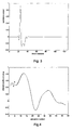
- Figure 2 shows an example of the cyclic correlation output for two transmitters.
- the cyclic correlation output shows separate impulse responses for different transmission antenna, which are separated by a delay equal to the cyclic shift applied in the subject transmitter.
- the code in this example is a length 64 Frank sequence that is two times over sampled, so there are 128 samples in one code length. All receivers will see a different cyclic correlation function from which they can extract the channel information.
- the reception means comprise a filter 51..54 which isolates the impulse response of the subject transmitter by multiplying the cyclic correlation output of the correlator 41.44 by a window function which is non-zero only at the desired impulse response.
- the window has smooth roll-off regions in order to minimize errors in the estimated channel frequency response.
- the roll-off factor is a compromise between frequency leakage and delay spread robustness; a larger roll-off region gives less frequency leakage but it also attenuates more impulse response components whose path delays fall within the roll-off region.
- Figure 3 shows an example of a windowed correlation function based on the correlator output shown in figure 2 .
- the windowed impulse response, taken at the output of the filter 51..54, is cyclically shifted back by a second correlator 61..64 to compensate for the cyclic shift applied at the transmitter.
- the channel frequency response is found by calculating a Fast Fourier Transform (FFT) over the windowed impulse response, taken at the output of the second correlator 61..64.
- the reception means comprise a FFT-filter 71..74.
- the FFT-filter 71..74 outputs resemble the channel coefficient values of all OFDM sub-carriers for one particular transmitter-receiver pair.
- the estimated channel frequency response for all sub-carrier is drawn as curve a in figure 4 , whereas curve b represents the actual values. At the lower sub-carriers there is a minor difference with the actual channel frequency response, which is assumed to be introduced by the windowing operation of the first filter 51..54.
- the invention may also be used for SDM on its own, i.e with merely a single carrier. If peak power is limited, which is often the case, then single carrier SDM training might require a separate training signal per transmit antenna instead of a common signal source.
- the training signal has to be long enough to get sufficient signal-to-noise ratio (SNR) at the receiver. Instead of sending separate training signals over the antennas one by one, one long training signal may then be transmitted simultaneously on all antennas.
- SNR signal-to-noise ratio
- the same procedure outlined above can be followed up to the cyclic correlation. The outputs of the cyclic correlation directly resemble the desired channel coefficients that are needed for a single carrier SDM receiver.
- the training time need not be longer than the duration of the training code c .
- a repetition of the training code is used in order to realise sufficient SNR at the receiver's end.
- the code c is preferably extended with a small dummy code preceding and following it. The addition of said dummy codes ascertains that the impulse responses associated with the different transmitters do not overlap mutually. This extended code is then stored in the look-up table of the training means 21..24. Even with this extension, the total training time need not be much longer than the duration of a training signal with sufficient SNR, whereas the prior art systems all require a multiple thereof.
- the training signal consists of a repetitive pattern with at least nearly ideal auto-correlation properties may also advantageously be used for frame detection and the detection of the carrier frequency offset.
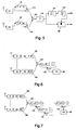
- Figure 5 shows a block diagram of a system that detects the start of a transmission and that estimates the carrier frequency offset in a communication system like that of figure 1 but with two transmitters and receivers.
- the reception means comprise delay means 81,82 to add a delay time T c to the received signal, where T c is equal to the duration of the training code c , and conversion means 91,92 to convert the delayed signal to a conjugated replica of it.
- This T c seconds delayed and conjugated replica is fed to correlation means 101.102. Because of the ideal auto-correlation properties of the code c , the correlation outputs consist only of the sum of n t auto-correlation points, whereas all cross-correlation products between signals coming from other transmitters are zero.
- the correlator output values are proportional to the total received power on each receiver.
- the phase of the correlator outputs is equal to 2B,f o .T c , where f o is the frequency offset between transmitter and receiver. If all transmitters and receivers from one SDM terminal share the same reference oscillator, only a single frequency offset has to be estimated and corrected.
- the correlator outputs are added at 105 and fed to summation means 110 to average the total in time. A start of a frame is detected by means of a comparator 120 which detects whether the magnitude of the absolute value 115 of the output signal of the summation means 110 exceeds some threshold *.
- the value of the threshold * is a tradeoff between the probability of a false alarm and the detection probability. If a start-of-transmission is detected, a trigger is raised at the output 130 of the circuit and at the same time the actual phase ⁇ of the summed correlator outputs is a measure for the carrier frequency offset.
- the frequency offset f o is given by the output phase ⁇ divided by 2B.f o .T c and may be derived at the output 140 of calculation means 125 in order to be fed to a frequency correction circuit.
- FIG. 6 shows a block diagram of an SDM synchronization system that finds the symbol timing based on knowledge of the transmitted training codes c.
- Each of the received signals is passed through a matched filter 151,152 with an impulse response equal to the conjugated and time-reversed code c.
- the matched filter output shows the correlation between the received signal and c.
- the power of the correlation outputs is calculated by taking the square of the output value with suitable means 160.
- the power outputs of all receivers are added at 165 to improve the signal-to-noise ratio (SNR) of the detector output.
- SNR signal-to-noise ratio
- a further SNR enhancement is obtained by adding signal components which are spaced apart by T d seconds at 170, where T d is equal to the cyclic time shift applied to the codes c in the SDM transmitters.
- the eventual output is fed to comparator 175 which selects the largest peak. The occurrence of this peak is a trigger that can be used for symbol timing.
- the circuit of figure 7 moreover comprises an extra FIR filter 174 that sums over multiple multipath components with a spacing of one sample interval T s .
- the number of taps L of this last FIR filter should preferably be such that L.T s is equal to the maximum tolerable delay spread that the receiver can tolerate. This structure gives an enhanced SNR performance in the case of multipath fading channels. In addition, it improves the maximum tolerable delay spread.
Landscapes
- Engineering & Computer Science (AREA)
- Computer Networks & Wireless Communication (AREA)
- Signal Processing (AREA)
- Power Engineering (AREA)
- Cable Transmission Systems, Equalization Of Radio And Reduction Of Echo (AREA)
- Synchronisation In Digital Transmission Systems (AREA)
Claims (10)
- Système de communication comprenant :un premier moyen de communication (10) ;un second moyen de communication (20) ; etun premier trajet d'émission ainsi qu'un autre trajet d'émission entre lesdits premier et second moyens de communication ;dans lequel :au moins le premier moyen de communication (10) est doté de moyens d'émission (11 à 14), destinés à chacun desdits trajets d'émission, qui sont capables d'envoyer au moins une partie d'un signal de communication vers le second moyen de communication (20) ;au moins le second moyen de communication (20) comprend un moyen de réception (31 à 34), destiné à chacun desdits trajets d'émission, qui est conçu pour recevoir au moins une partie dudit signal de communication ; etau moins le premier moyen de communication (10) comprend un moyen d'apprentissage (21 à 24) destiné à produire un code d'apprentissage composé d'un certain nombre de signaux de données connus à envoyer vers le moyen de réception (31 à 34), dans au moins un symbole d'apprentissage qui précède des informations à envoyer vers le moyen de réception, pour permettre au moyen de réception (31 à 34) de reconstituer des facteurs d'émission et d'appliquer les facteurs d'émission auxdites informations pour reconstituer à partir d'un signal reçu un signal émis correspondant ;dans lequel :le moyen d'apprentissage (21 à 24) est conçu pour produire un code d'apprentissage avec des propriétés d'autocorrélation cycliques, si bien que sa fonction d'autocorrélation est nulle pour tous les décalages cycliques et non nulle pour lui-même ;les moyens d'émission (11 à 14) pour les trajets d'émission sont conçus pour envoyer concurremment ledit code d'apprentissage afin que chaque moyen d'émission (11 à 14) émette ledit code d'apprentissage avec un décalage cyclique différent ; etle moyen de réception (31 à 34) est conçu pour réaliser une autocorrélation cyclique sur un code d'apprentissage reçu.
- Système de communication selon la revendication 1, dans lequel les moyens de réception (31 à 34) sont capables de produire les décalages cycliques d'un code d'apprentissage reçu et de corréler ceux-ci avec ledit code d'apprentissage.
- Système de communication selon la revendication 1 ou la revendication 2, dans lequel le code d'apprentissage comprend une concaténation des lignes d'une matrice de Fourier.
- Système de communication selon la revendication 3, dans lequel le code d'apprentissage a une longueur qui est égale au nombre des trajets d'émission ou à un entier multiple de celui-ci.
- Système de communication selon l'une quelconque des revendications précédentes, dans lequel, en service, les codes d'apprentissage sont précédés et suivis d'un code factice.
- Système de communication selon l'une quelconque des revendications précédentes, dans lequel le moyen de séquence d'apprentissage comprend un filtre de pré-correction destiné à traiter le code d'apprentissage.
- Système de communication selon l'une quelconque des revendications précédentes, dans lequel le moyen d'apprentissage (21 à 24) comprend un moyen de stockage destiné à stocker un ou plusieurs codes d'apprentissage.
- Système de communication selon l'une quelconque des revendications précédentes, dans lequel le moyen d'apprentissage (21 à 24), en service, émet un certain nombre de codes d'apprentissage au moins identiques et en ce que les moyens de réception (31 à 34) comprennent un moyen de sommation pour calculer la moyenne des codes d'apprentissage reçus.
- Système de communication selon l'une quelconque des revendications précédentes, dans lequel le moyen d'apprentissage, au moins pendant le service, émet au moins des codes d'apprentissage à un intervalle fixe et en ce que les moyens de réception (31 à 34) sont dotés d'un moyen d'autocorrélation destiné à corréler un signal reçu avec un ou plusieurs signaux reçus après un retard correspondant audit intervalle ou à un entier multiple de celui-ci.
- Système de communication selon l'une quelconque des revendications précédentes, dans lequel les différents moyens d'émission (11 à 14) et moyens de réception (31 à 34) possèdent chacun leur propre antenne.
Priority Applications (4)
| Application Number | Priority Date | Filing Date | Title |
|---|---|---|---|
| EP00310085A EP1206061B1 (fr) | 2000-11-13 | 2000-11-13 | Estimation de canal pour systèmes de communication en diversité d'espace |
| DE60042408T DE60042408D1 (de) | 2000-11-13 | 2000-11-13 | Kanalschätzung für Raumdiversitätskommunikationssystemen |
| US10/006,900 US7099269B2 (en) | 2000-11-13 | 2001-11-13 | Methods and apparatus for generating and utilizing training codes in a space division multiplexing communication system |
| US11/482,316 US20070058694A1 (en) | 2000-11-13 | 2006-07-07 | Methods and apparatus for generating and utilizing training codes in a space division multiplexing communication system |
Applications Claiming Priority (1)
| Application Number | Priority Date | Filing Date | Title |
|---|---|---|---|
| EP00310085A EP1206061B1 (fr) | 2000-11-13 | 2000-11-13 | Estimation de canal pour systèmes de communication en diversité d'espace |
Publications (2)
| Publication Number | Publication Date |
|---|---|
| EP1206061A1 EP1206061A1 (fr) | 2002-05-15 |
| EP1206061B1 true EP1206061B1 (fr) | 2009-06-17 |
Family
ID=8173394
Family Applications (1)
| Application Number | Title | Priority Date | Filing Date |
|---|---|---|---|
| EP00310085A Expired - Lifetime EP1206061B1 (fr) | 2000-11-13 | 2000-11-13 | Estimation de canal pour systèmes de communication en diversité d'espace |
Country Status (3)
| Country | Link |
|---|---|
| US (2) | US7099269B2 (fr) |
| EP (1) | EP1206061B1 (fr) |
| DE (1) | DE60042408D1 (fr) |
Families Citing this family (32)
| Publication number | Priority date | Publication date | Assignee | Title |
|---|---|---|---|---|
| EP1206061B1 (fr) * | 2000-11-13 | 2009-06-17 | Lucent Technologies Inc. | Estimation de canal pour systèmes de communication en diversité d'espace |
| US7898972B2 (en) * | 2002-01-17 | 2011-03-01 | Agere Systems Inc. | Auxiliary coding for home networking communication system |
| US7254196B2 (en) * | 2002-11-26 | 2007-08-07 | Agere Systems Inc. | Symbol timing for MIMO OFDM and other wireless communication systems |
| US8743837B2 (en) * | 2003-04-10 | 2014-06-03 | Qualcomm Incorporated | Modified preamble structure for IEEE 802.11A extensions to allow for coexistence and interoperability between 802.11A devices and higher data rate, MIMO or otherwise extended devices |
| US7916803B2 (en) | 2003-04-10 | 2011-03-29 | Qualcomm Incorporated | Modified preamble structure for IEEE 802.11a extensions to allow for coexistence and interoperability between 802.11a devices and higher data rate, MIMO or otherwise extended devices |
| US7242722B2 (en) * | 2003-10-17 | 2007-07-10 | Motorola, Inc. | Method and apparatus for transmission and reception within an OFDM communication system |
| US7453949B2 (en) | 2003-12-09 | 2008-11-18 | Agere Systems Inc. | MIMO receivers having one or more additional receive paths |
| JP4212548B2 (ja) | 2003-12-26 | 2009-01-21 | 株式会社東芝 | 無線送信装置、無線受信装置、無線送信方法及び無線受信方法 |
| ES2885101T3 (es) | 2004-01-29 | 2021-12-13 | Neo Wireless Llc | Procedimientos y aparatos para superponer señales de espectro ensanchado de secuencia directa y de múltiples portadoras en un sistema de comunicación inalámbrica de banda ancha |
| US7995967B2 (en) | 2004-03-09 | 2011-08-09 | Neocific, Inc | Methods and apparatus for random access in multi-carrier communication systems |
| US7742533B2 (en) | 2004-03-12 | 2010-06-22 | Kabushiki Kaisha Toshiba | OFDM signal transmission method and apparatus |
| EP1751890B1 (fr) * | 2004-05-27 | 2017-03-01 | QUALCOMM Incorporated | Structure de preambule modifie pour extensions ieee 802.11a permettant la coexistence et l'interoperabilite entre des dispositifs 802.11a et des dispositifs a debit plus eleve, mimo ou presentant d'autres types d'extensions |
| KR100899749B1 (ko) * | 2005-01-13 | 2009-05-27 | 삼성전자주식회사 | 다중 입력 다중 출력 방식을 사용하는 직교 주파수 분할 다중 통신시스템에서 프리앰블 시퀀스 송수신 방법 |
| JP4695150B2 (ja) * | 2005-02-08 | 2011-06-08 | クゥアルコム・インコーポレイテッド | ビームフォーミングとレガシー・デバイスの共存を考慮する無線メッセージ通信プリアンブル |
| EP1878133B1 (fr) * | 2005-04-26 | 2015-03-04 | Intellectual Ventures I LLC | Systemes et procedes permettant l'expansion de la diversite des emetteurs |
| US20070183386A1 (en) * | 2005-08-03 | 2007-08-09 | Texas Instruments Incorporated | Reference Signal Sequences and Multi-User Reference Signal Sequence Allocation |
| WO2007049777A1 (fr) * | 2005-10-25 | 2007-05-03 | Nec Corporation | Unite de telephone mobile, circuit codec utilise dans cette unite, et procede de reglage automatique de niveau sonore de haut-parleur de telephone |
| KR101306696B1 (ko) * | 2005-11-10 | 2013-09-10 | 엘지전자 주식회사 | 다수의 반송파를 이용하여 데이터를 전송하는 장치 및 방법 |
| US8130857B2 (en) | 2006-01-20 | 2012-03-06 | Qualcomm Incorporated | Method and apparatus for pilot multiplexing in a wireless communication system |
| EP1985023A4 (fr) * | 2006-01-25 | 2014-08-13 | Texas Instruments Inc | Procédé et dispositif permettant d'augmenter le nombre de signaux orthogonaux utilisant l'étalement de blocs |
| KR101294781B1 (ko) * | 2006-08-08 | 2013-08-09 | 엘지전자 주식회사 | 랜덤 액세스 프리앰블 전송 방법 |
| EP2051426A1 (fr) * | 2006-08-08 | 2009-04-22 | Panasonic Corporation | Appareil de transmission radio multi-antenne et procede de transmission radio multi-antenne |
| WO2008038388A1 (fr) * | 2006-09-28 | 2008-04-03 | Fujitsu Microelectronics Limited | Appareil récepteur de signaux et procédé de mise en forme d'ondes |
| US8681750B2 (en) * | 2006-12-29 | 2014-03-25 | Nokia Corporation | Apparatus, methods, and computer program products providing limited use of Zadoff-Chu sequences in pilot or preamble signals |
| EP3767908A1 (fr) * | 2007-01-05 | 2021-01-20 | LG Electronics Inc. | Procédé pour régler une commutation cyclique en tenant compte du décalage de fréquence |
| EP2458805B1 (fr) | 2007-01-05 | 2018-06-27 | LG Electronics Inc. | Procédé pour régler une commutation cyclique en tenant compte du décalage de fréquence |
| US7738548B2 (en) * | 2007-01-08 | 2010-06-15 | Harris Corporation | System and method for communicating at low signal-to-noise ratio using injected training symbols |
| US9065714B2 (en) * | 2007-01-10 | 2015-06-23 | Qualcomm Incorporated | Transmission of information using cyclically shifted sequences |
| US8953562B2 (en) * | 2007-02-01 | 2015-02-10 | Alcatel Lucent | Method of using uplink reference signals for access grant requests |
| US8615211B2 (en) * | 2010-01-27 | 2013-12-24 | Agency For Science, Technology And Research | Method for spectrum sensing and communication device |
| EP2675072A1 (fr) * | 2012-06-15 | 2013-12-18 | Fraunhofer-Gesellschaft zur Förderung der angewandten Forschung e.V. | Procédé de diffusion de plusieurs symboles de données sur des sous-porteuses d'un signal de transport |
| CN109561042B (zh) * | 2018-12-17 | 2021-07-02 | 电子科技大学 | 一种ofdm系统接收机的定时频率同步方法 |
Family Cites Families (13)
| Publication number | Priority date | Publication date | Assignee | Title |
|---|---|---|---|---|
| FR2556474B1 (fr) * | 1983-12-07 | 1986-09-05 | Trt Telecom Radio Electr | Dispositif de localisation d'un point de reflexion de signal sur une ligne de transmission |
| US4761796A (en) * | 1985-01-24 | 1988-08-02 | Itt Defense Communications | High frequency spread spectrum communication system terminal |
| DE69024525T2 (de) * | 1989-05-02 | 1996-05-15 | Nippon Electric Co | TDMA-Raumdiversity-Empfänger |
| DE69432013T2 (de) * | 1993-10-12 | 2003-10-09 | Ntt Mobile Communications Network Inc., Tokio/Tokyo | Übertragungsverfahren mit mehreren stationen und empfänger dafür |
| US5450456A (en) * | 1993-11-12 | 1995-09-12 | Daimler Benz Ag | Method and arrangement for measuring the carrier frequency deviation in a multi-channel transmission system |
| US5790598A (en) * | 1996-03-01 | 1998-08-04 | Her Majesty The Queen In Right Of Canada | Block decision feedback equalizer |
| US6307882B1 (en) * | 1998-07-10 | 2001-10-23 | Lucent Technologies Inc. | Determining channel characteristics in a space-time architecture wireless communication system having multi-element antennas |
| US6515978B1 (en) * | 1999-04-19 | 2003-02-04 | Lucent Technologies Inc. | Methods and apparatus for downlink diversity in CDMA using Walsh codes |
| US6175559B1 (en) * | 1999-07-07 | 2001-01-16 | Motorola, Inc. | Method for generating preamble sequences in a code division multiple access system |
| US6377636B1 (en) * | 1999-11-02 | 2002-04-23 | Iospan Wirless, Inc. | Method and wireless communications system using coordinated transmission and training for interference mitigation |
| US6804307B1 (en) * | 2000-01-27 | 2004-10-12 | Telefonaktiebolaget Lm Ericsson (Publ) | Method and apparatus for efficient transmit diversity using complex space-time block codes |
| US6473467B1 (en) * | 2000-03-22 | 2002-10-29 | Qualcomm Incorporated | Method and apparatus for measuring reporting channel state information in a high efficiency, high performance communications system |
| EP1206061B1 (fr) * | 2000-11-13 | 2009-06-17 | Lucent Technologies Inc. | Estimation de canal pour systèmes de communication en diversité d'espace |
-
2000
- 2000-11-13 EP EP00310085A patent/EP1206061B1/fr not_active Expired - Lifetime
- 2000-11-13 DE DE60042408T patent/DE60042408D1/de not_active Expired - Lifetime
-
2001
- 2001-11-13 US US10/006,900 patent/US7099269B2/en not_active Expired - Lifetime
-
2006
- 2006-07-07 US US11/482,316 patent/US20070058694A1/en not_active Abandoned
Also Published As
| Publication number | Publication date |
|---|---|
| US20020118635A1 (en) | 2002-08-29 |
| US20070058694A1 (en) | 2007-03-15 |
| DE60042408D1 (de) | 2009-07-30 |
| EP1206061A1 (fr) | 2002-05-15 |
| US7099269B2 (en) | 2006-08-29 |
Similar Documents
| Publication | Publication Date | Title |
|---|---|---|
| EP1206061B1 (fr) | Estimation de canal pour systèmes de communication en diversité d'espace | |
| EP2099187B1 (fr) | Système sans fil utilisant un nouveau type de préambule pour trame de rafale | |
| US8332732B2 (en) | Common air interface supporting single carrier and OFDM | |
| EP2637318B1 (fr) | Procédé et système de synchronisation dans un système de communication | |
| US7957361B2 (en) | Transmitter, transmitting method, receiver, and receiving method for MC-CDMA communication system | |
| EP1041790B1 (fr) | Synchronisation de symbole pour démodulateur OFDM | |
| EP1245100B1 (fr) | Estimation de voie pour les systemes de communication duplex a repartition dans le temps | |
| US20080043858A1 (en) | Method for Constructing Frame Preamble in Ofdm Wireless Communication System, and Method for Acquiring Frame Synchronization and Searching Cells Using Preamble | |
| KR100781969B1 (ko) | 직교 주파수 분할 다중 접속에 기반한 데이타 통신 장치및 방법 | |
| US7099353B2 (en) | Orthogonal frequency division multiplexing system with superframe synchronization using correlation sequence | |
| WO2007119280A1 (fr) | Appareil de réception de type mimo et procédé de réception | |
| CN101128989A (zh) | 用于同步无线接收机的方法和装置 | |
| US20030152023A1 (en) | Orthogonal frequency division multiplexing system with differing control parameters corresponding to different data points in a single symbol | |
| EP1908242B1 (fr) | Procédé et appareil pour la transmission de symboles pilotes dans un système de communication sans fil | |
| US7120201B2 (en) | Method and system for optimization of channel estimation and synchronization in an OFDM-MIMO wireless communication system | |
| CN108206801B (zh) | 循环频移正交分频多工的展频装置 | |
| US8750436B2 (en) | Method and apparatus for channel estimation | |
| EP1555782A2 (fr) | Procédé de conception d'un signal pilot de sens montant et procédé et système d'estimation du canal dans un système multiporteur à accès multiple par répartition par codes | |
| KR101001663B1 (ko) | 무선 통신시스템의 수신 신호 심벌 동기를 검출하는 장치및 방법 | |
| EP1437869B1 (fr) | Estimation de canal pour un système de communication duplex à répartition dans le temps |
Legal Events
| Date | Code | Title | Description |
|---|---|---|---|
| PUAI | Public reference made under article 153(3) epc to a published international application that has entered the european phase |
Free format text: ORIGINAL CODE: 0009012 |
|
| AK | Designated contracting states |
Kind code of ref document: A1 Designated state(s): AT BE CH CY DE DK ES FI FR GB GR IE IT LI LU MC NL PT SE TR |
|
| AX | Request for extension of the european patent |
Free format text: AL;LT;LV;MK;RO;SI |
|
| 17P | Request for examination filed |
Effective date: 20020628 |
|
| AKX | Designation fees paid |
Designated state(s): DE FR GB |
|
| 17Q | First examination report despatched |
Effective date: 20061206 |
|
| GRAP | Despatch of communication of intention to grant a patent |
Free format text: ORIGINAL CODE: EPIDOSNIGR1 |
|
| GRAS | Grant fee paid |
Free format text: ORIGINAL CODE: EPIDOSNIGR3 |
|
| GRAA | (expected) grant |
Free format text: ORIGINAL CODE: 0009210 |
|
| AK | Designated contracting states |
Kind code of ref document: B1 Designated state(s): DE FR GB |
|
| REG | Reference to a national code |
Ref country code: GB Ref legal event code: FG4D |
|
| REF | Corresponds to: |
Ref document number: 60042408 Country of ref document: DE Date of ref document: 20090730 Kind code of ref document: P |
|
| RAP4 | Party data changed (patent owner data changed or rights of a patent transferred) |
Owner name: LUCENT TECHNOLOGIES INC. |
|
| PLBE | No opposition filed within time limit |
Free format text: ORIGINAL CODE: 0009261 |
|
| STAA | Information on the status of an ep patent application or granted ep patent |
Free format text: STATUS: NO OPPOSITION FILED WITHIN TIME LIMIT |
|
| 26N | No opposition filed |
Effective date: 20100318 |
|
| REG | Reference to a national code |
Ref country code: FR Ref legal event code: PLFP Year of fee payment: 16 |
|
| PGFP | Annual fee paid to national office [announced via postgrant information from national office to epo] |
Ref country code: GB Payment date: 20151027 Year of fee payment: 16 |
|
| PGFP | Annual fee paid to national office [announced via postgrant information from national office to epo] |
Ref country code: FR Payment date: 20151023 Year of fee payment: 16 |
|
| GBPC | Gb: european patent ceased through non-payment of renewal fee |
Effective date: 20161113 |
|
| REG | Reference to a national code |
Ref country code: FR Ref legal event code: ST Effective date: 20170731 |
|
| PG25 | Lapsed in a contracting state [announced via postgrant information from national office to epo] |
Ref country code: FR Free format text: LAPSE BECAUSE OF NON-PAYMENT OF DUE FEES Effective date: 20161130 |
|
| PG25 | Lapsed in a contracting state [announced via postgrant information from national office to epo] |
Ref country code: GB Free format text: LAPSE BECAUSE OF NON-PAYMENT OF DUE FEES Effective date: 20161113 |
|
| REG | Reference to a national code |
Ref country code: DE Ref legal event code: R082 Ref document number: 60042408 Country of ref document: DE Representative=s name: DILG, HAEUSLER, SCHINDELMANN PATENTANWALTSGESE, DE Ref country code: DE Ref legal event code: R082 Ref document number: 60042408 Country of ref document: DE Representative=s name: DILG HAEUSLER SCHINDELMANN PATENTANWALTSGESELL, DE Ref country code: DE Ref legal event code: R081 Ref document number: 60042408 Country of ref document: DE Owner name: AVAGO TECHNOLOGIES GENERAL IP (SINGAPORE) PTE., SG Free format text: FORMER OWNER: LUCENT TECHNOLOGIES INC., MURRAY HILL, N.J., US Ref country code: DE Ref legal event code: R081 Ref document number: 60042408 Country of ref document: DE Owner name: AVAGO TECHNOLOGIES INTERNATIONAL SALES PTE. LI, SG Free format text: FORMER OWNER: LUCENT TECHNOLOGIES INC., MURRAY HILL, N.J., US |
|
| REG | Reference to a national code |
Ref country code: DE Ref legal event code: R081 Ref document number: 60042408 Country of ref document: DE Owner name: AVAGO TECHNOLOGIES INTERNATIONAL SALES PTE. LI, SG Free format text: FORMER OWNER: AVAGO TECHNOLOGIES GENERAL IP (SINGAPORE) PTE. LTD., SINGAPORE, SG Ref country code: DE Ref legal event code: R082 Ref document number: 60042408 Country of ref document: DE Representative=s name: DILG, HAEUSLER, SCHINDELMANN PATENTANWALTSGESE, DE Ref country code: DE Ref legal event code: R082 Ref document number: 60042408 Country of ref document: DE Representative=s name: DILG HAEUSLER SCHINDELMANN PATENTANWALTSGESELL, DE |
|
| PGFP | Annual fee paid to national office [announced via postgrant information from national office to epo] |
Ref country code: DE Payment date: 20191127 Year of fee payment: 20 |
|
| REG | Reference to a national code |
Ref country code: DE Ref legal event code: R071 Ref document number: 60042408 Country of ref document: DE |