EP1206407B1 - Procede et dispositif pour receptionner au moins deux feuilles placees a la maniere d'ecailles dans une machine de manipulation de feuilles - Google Patents
Procede et dispositif pour receptionner au moins deux feuilles placees a la maniere d'ecailles dans une machine de manipulation de feuilles Download PDFInfo
- Publication number
- EP1206407B1 EP1206407B1 EP00949482A EP00949482A EP1206407B1 EP 1206407 B1 EP1206407 B1 EP 1206407B1 EP 00949482 A EP00949482 A EP 00949482A EP 00949482 A EP00949482 A EP 00949482A EP 1206407 B1 EP1206407 B1 EP 1206407B1
- Authority
- EP
- European Patent Office
- Prior art keywords
- sheet
- sheets
- speed
- transport unit
- transport direction
- Prior art date
- Legal status (The legal status is an assumption and is not a legal conclusion. Google has not performed a legal analysis and makes no representation as to the accuracy of the status listed.)
- Expired - Lifetime
Links
Images


Classifications
-
- B—PERFORMING OPERATIONS; TRANSPORTING
- B65—CONVEYING; PACKING; STORING; HANDLING THIN OR FILAMENTARY MATERIAL
- B65H—HANDLING THIN OR FILAMENTARY MATERIAL, e.g. SHEETS, WEBS, CABLES
- B65H33/00—Forming counted batches in delivery pile or stream of articles
- B65H33/12—Forming counted batches in delivery pile or stream of articles by creating gaps in the stream
-
- B—PERFORMING OPERATIONS; TRANSPORTING
- B65—CONVEYING; PACKING; STORING; HANDLING THIN OR FILAMENTARY MATERIAL
- B65H—HANDLING THIN OR FILAMENTARY MATERIAL, e.g. SHEETS, WEBS, CABLES
- B65H29/00—Delivering or advancing articles from machines; Advancing articles to or into piles
- B65H29/66—Advancing articles in overlapping streams
- B65H29/6654—Advancing articles in overlapping streams changing the overlapping figure
-
- B—PERFORMING OPERATIONS; TRANSPORTING
- B65—CONVEYING; PACKING; STORING; HANDLING THIN OR FILAMENTARY MATERIAL
- B65H—HANDLING THIN OR FILAMENTARY MATERIAL, e.g. SHEETS, WEBS, CABLES
- B65H2301/00—Handling processes for sheets or webs
- B65H2301/40—Type of handling process
- B65H2301/44—Moving, forwarding, guiding material
- B65H2301/445—Moving, forwarding, guiding material stream of articles separated from each other
- B65H2301/4454—Merging two or more streams
-
- B—PERFORMING OPERATIONS; TRANSPORTING
- B65—CONVEYING; PACKING; STORING; HANDLING THIN OR FILAMENTARY MATERIAL
- B65H—HANDLING THIN OR FILAMENTARY MATERIAL, e.g. SHEETS, WEBS, CABLES
- B65H2511/00—Dimensions; Position; Numbers; Identification; Occurrences
- B65H2511/20—Location in space
- B65H2511/22—Distance
Definitions
- the present invention relates to a method and a device for taking over at least two, in one Sheet or paper running direction arranged in shingles Scrolling into a sheet or paper handling machine, in which the at least two sheets after the takeover with one first speed to be moved.
- Paper handling systems are known in the prior art, where, for example, 2-use printed sheets one Cutting machine are fed, separated by this are provided, and subsequent processing become.
- the 2-up are printed Sheets using suitable machines, e.g. mergers, placed on top of each other and thus lie for further processing on subsequent paper handling machines.
- Sheets take over the following machines, per machine cycle, a sheet provided, depending on the downstream machines, for example from the provided Scroll individual groups are formed must then be inserted, for example.
- the cycle with which the cutting machine works and with which the individual sheets to the subsequent machines provided is higher than the clock cycle of one subsequent inserter. Let’s take as an example that the cutting machine for a fixed period of time Can cut 1000 times while the inserter 100 times can insert. This leads to a first Case in which the inserter only processes single sheets, the cutting machine is stopped regularly because there are too many Leaves would be provided by this, whereas in a second case, in which the inserter fifteen Sheets inserted, the inserter stopped regularly must be because the cutting machine is not sufficient can provide many sheets.
- the individual from the cutting machine output sheets entered into the buffer, and after reaching a predetermined number of sheets, e.g. switched to a second buffer level, so that the in the first buffer level contain sheets of further processing can be fed while simultaneously in the second buffer sheets output from the cutting machine can be entered.
- a predetermined number of sheets e.g. switched to a second buffer level
- Such a device is for example in U.S. Patent 5,083,769.
- US-A-4,040,617 relates to a sheet overlap device which between a fast and a slow conveyor is positioned to sheets from the fast conveyor slow down and the same on an overlapping Way to transfer into the slow conveyor. It describes a sheet overlap device that is slightly different from each other separately arranged sheets by a cutter be fed from the quick to the slow conveyor transferred. The takeover of in a sheet running direction is arranged overlapping sheets not described.
- the present Invention based on the object, a method and a To create device that is simple and accelerated Group formation with a minimum number of required Support machine clocks in paper handling systems.
- the present invention provides an apparatus for transferring at least two sheets that are shingled in a sheet travel direction into a sheet handling machine, which comprises a transport unit that moves the at least two sheets after transfer at a first speed, a first sheet and a second sheet of the at least two sheets are offset by an offset in the paper travel direction an infeed roller which feeds the at least two sheets of the sheet handling machine at a second speed, the second speed being higher than the first speed; and a brake roller which brakes the second sheet to a third speed as soon as the first sheet is braked by the transport unit, the third speed being lower than the second speed.
- the present invention is based on the finding that that by the advancement of the invention to be processed Leaves the disadvantages described above in the prior art Technology can be overcome by the 2-way printed Leaves superimposed with a small longitudinal offset become, i.e. the leaves are scaled so that these are easy to separate later. In a simple way and In this way, larger groups can be formed by using further, already pre-scaled leaves, a larger one Scale flow is formed.
- the known in the prior art Machines enable such an approach not, but only allow the formation of the shingled stream from single sheets or with non-offset double benefit.
- the present invention has the advantage that by the inventive method and the inventive Device for taking over in one cycle at least two leaves that are already shingled into one Paper handling machine can be taken over without that, as would be the case with the prior art, they were scaled Leaves would slide together again. According to the invention this problem is solved in that the leading Sheet on the leading edge of the sheet and the trailing one Leaf at the rear edge of the leaf is braked.
- the first speed is equal to the third speed.
- the thus formed is then transported onward Group and the resulting scale flow by one Distance equal to the number of sheets in the group times the scale length, moving to a subsequent one Transport takes place, which then takes over the group.
- a further transport unit is additionally provided, to which the in the first transport unit continuously collected and flaked leaves Reaching a predetermined number of sheets in the first Transport unit will be handed over, the second Transport unit depending on the number of items to be output Scrolling is moved clocked, so that the stored therein Shingled stream is moved towards an output unit, where on the output unit each in the paper travel direction front sheet output from the paper handling machine becomes.
- the advantage of the present invention is that this is a continuous inflow of the merged leaves enables and with it a high performance increase.
- a process that involves the provision of at least allows two leaves in a scaly shape is in described in DE 199 35 186 A.
- the present invention enables the operation of a paper handling machine with medium group sizes, the number of leaves per Groups between which the above limits lie a precursor machine (e.g. cutting machine) or one Follower machine (e.g. inserter) must be stopped.
- a precursor machine e.g. cutting machine
- one Follower machine e.g. inserter
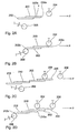
- FIG. 1 schematically shows an example of a paper handling system shown, which is essentially four separate Sections A - D includes.
- Section A of the paper handling system becomes 2-use printed sheets 100 fed to a cutting machine, and the paper web is cut lengthways and crossways around the cut sheets 100a and 100b, which are described in section B are merged in such a way that the Leaves 100a and 100b are arranged in shingled relationship thus in a sheet or paper running direction P by a predetermined Offset (scale length) X are shifted.
- the merger section B the two are arranged in shingles Pass sheets 100a and 100b to section C, in which the fed sheets are cached before in section D e.g. passed on to a collecting station become.
- Section C is divided into sections C1 and C2, wherein section C1 is a section of the sheet handling machine represents, which is based on 3 is described in more detail. Section C2 also provides a section of the paper handling machine , which are described in more detail below using the Fig. 5 is described. Section C presents in its Taken as a whole, the paper handling machine described later in FIG. 6 represents.
- section C1 the scaly leaves are arranged 100a and 100b continuously fed until a predetermined one Number is reached, and then the one so formed Scale flow in a single cycle to section C2 transferred from which, then, clocked, single sheets or Groups of sheets are fed to the collecting station, such as this will be described in detail later.
- Group 1 is shown as an example in section A and B, like single sheets or groups of sheets in the double benefit are arranged. Leaves belonging to the same group are labeled with the same lowercase letters.
- the Group a comprises only one sheet, which comprises group b two sheets, and group c comprises three sheets.
- the present invention works from already scaled leaves, whereby in the following description of the invention Method and the device according to the invention first for the sake of simplicity, it is assumed that only two flaky leaves are to be taken over.
- FIG. 2A The situation is illustrated schematically in FIG. 2A, in which is a first sheet 200 and a second sheet 202 in one Direction of paper or sheet of a direction not shown in detail Paper handling machine can be fed. How to the first sheet is 200 and the second sheet 202 in the paper running direction P by the one already described Offset X arranged shifted, so have a scale length X on that in a preferred embodiment 20 mm, but are in the range of 10 mm to 50 mm can.
- the offset X or the scale length X is defined by the distance of the front edge 200a in the paper running direction P of the first sheet 200 to the front in the paper running direction P. Edge 202a of the second sheet.
- Fig. 2a is also schematically a first scale roll 204 depicted with respect to sheets 200 and 202 is arranged.
- the scale roll 204 is part of a first transport unit shown in the following figures is described in more detail.
- a brake roller 206 is shown which is relative to the blades 200 and 202 between a first position and a second Position is movable, the brake roller 206 in Fig. 2A is in its first position in which it is sheets 200 and 202 is not engaged.
- Sheets 200 and 202 are not replaced by one in FIG shown feeder at a second speed supplied according to a preferred embodiment is about 3 m / s, but also in the range of Can be 2 m / s to 6 m / s.
- the scale roller 204 is part of the transport unit to be described below, which moves the picked up or taken over sheets at a speed which is preferably approximately 0.25 m / s, but in the range of 0.2 m / s s can be up to 2 m / s.
- the brake roller 206 is of its in Fig. 2A shown in its first position shown in FIG. 2B Switched position in the same with one in the paper running direction rear edge 202b of the second sheet 202 engaging takes and brakes them so that the shingled arrangement the two sheets 200 and 202 are retained.
- the Brake roller causes the second blade 202 to speed up is braked by about 2 m / s, but can this speed also in the range of 0.2 m / s to 2 m / s lie.
- the brake roller 206 is switched as soon as the first one Sheet 206 has reached the scale roll 204.
- the first speed Transport speed
- the third speed Deceleration speed
- the transport unit for moving the taken over Sheets are driven continuously, and after reaching them the first scale roll 204 turns the two sheets around moved a distance equal to the number of Leaves times the scale length X is.
- sheets 200 and 202 were taken from the Situation in Fig. 2C so that the sheet 200 now is present on the scale roller 208.
- the new sheet 210 reached with its front edge 210a in the paper running direction the first scale roller 204 and is braked there, and at the same time the brake roller 206 is actuated, who switched from their first to their second position to have a rear edge 212b in the paper travel direction of the second sheet 212 to engage that sheet braking in the manner already described above, so that the new sheets 210 and 212 slide together avoid.
- 2E shows a further exemplary embodiment of the invention Procedure shown in which instead of two sheets described so far four sheets 214, 216, 218, 220 are supplied.
- 2E shows the situation, in which the sheet 214 already on the scale roll 204 has arrived so that the supplied sheets are braked become.
- FIG. 3 is a first section of the paper handling machine shown which is a first embodiment of the invention Device implemented.
- the portion of the device shown in Fig. 3 is in provided with the reference number 300 in its entirety.
- the Section 300 includes an inlet section 302 and one first transport unit 304.
- the inlet section 302 includes an inlet 306 that passes through two guides 306a converging in the paper running direction P. and 306b, and for feeding the at least two Sheets in the paper running direction P to the section 300 is used.
- Adjacent to the front ends of the paper in direction P Guides 306a and 306b is a pair of feed rollers 308a, 308b arranged, the feed roller 308a by a, in Fig. 3 motor, not shown, is driven.
- the pressure force between the rollers 308a and 308b can over a Adjustment screw 310, by means of the position of the roller 308b can be changed with respect to the roller 308a become.
- the rollers 308a and 308b are on a frame 312 of the inlet section 302.
- the infeed rollers 308a and 308b are driven to feed sheets preferably at a speed of 2 m / s to 6 m / s of 3 m / s.
- the trap 314 includes a deflecting element 316, as well as two arranged adjacent to the deflecting element Deflection guides 318a and 318b.
- the deflection device 316 can between the position shown in Fig. 3, in the whose rear tip in the paper running direction is adjacent to the Infeed roller 308a is arranged in a second position can be switched over in the direction in which the paper runs Tip of the deflector 316 adjacent to the Roll 308b is shown.
- the Deflection device 316 Depending on the position of the Deflection device is by the deflection device 316 and the respective deflection guide 318a or 318b is a first leaf path 320a or a second leaf path 320b is formed, via which the sheets fed toward the transport unit 304 be moved.
- the trap 314 allows the fed "Double sheets" optionally, depending on the position of the Trap, scaled ascending or descending in the direction of the transport unit 304 to move.
- Each of the sheet paths 320a and 320b is a brake roller 323a and 323b.
- a magnetic Actuator 324a and 324b becomes the respective brake roller 322a or 322b from their first position, in which no intervention with the leaves fed through the leaf paths, moved to its second position in which an engagement with the rear edge of the second sheet of the fed Sheets are made to slow this down.
- the braking speed is in the range of 0.2 m / s to 2 m / s, preferably at 2 m / s.
- the brake roller 322a is released after the activation of the Actuator 324a by gravitational force into its first Position moves back, whereas roller 322b after completion activation of actuator 324b by the restoring force a spring 326 in its rest or first position is moved back.
- a spring 326 in its rest or first position is moved back.
- the rollers 330a and 330b are carried in a frame 332, which is shown schematically in FIG. 3.
- Four scale rollers 334a-334d are further provided which are arranged in contact with the conveyor belt 328 and are spaced apart from one another by a distance which is dependent on the number of sheets fed simultaneously and the offset of the sheets.
- the individual scale rollers 334a-334d are movably attached (see arrow 336) to a chain 338, which is shown schematically in FIG. 3.
- the chain shown schematically is guided over transport rollers 340a and 340b, also shown schematically.
- the chain in conjunction with the scale rollers, serves to adjust the transport unit 304 to certain formats of the sheets.
- the transport unit described is only shown schematically, and it is obvious that the number and the distance of the rolls depends on the sheets or sheet formats used (pre-printing height) and the number of sheets to be picked up. In the figure, an example is shown in which the rollers are arranged 3 "(7.62 cm) apart.
- the transport unit 304 also includes, for safe takeover the fed double sheets from the inlet 302, two parallel guides 342 and 344, which are extend along the entire transport unit 304.
- section 300 is such that the Double sheets are fed through inlet 306, and once the first of the double sheets the first scale roll 334a reached, the double sheets are braked, and to Avoiding the leaves sliding on each other becomes too the time at which a leading edge of the first sheet the scale roller 334a reaches one of the brake rollers 322a or 322b by actuating the corresponding actuator activated so with a rear edge of the second Leaf of the double leaves to engage so that a Sliding the sheets together is avoided. Subsequently the sheets are moved further by the transport unit 304, with additional double sheets fed simultaneously until a predetermined number of double sheets is contained in the transport unit 304. As soon as contain the predetermined number of sheets in unit 304 is, these are in one measure to a subsequent one Transport unit, which will be described later, passed on.
- the trap can, for example be omitted entirely, or double Brake rollers can, for example, by a single brake roller, which is subordinate to the trap.
- a brake roller can be used which have increased running resistance compared to conventional rollers has, so that by pressing them against a rear Edge on the second sheet a corresponding delay the same is achieved.
- FIG. 4A to 4C is the operation of a second section the paper handling machine schematically explained.
- the portion of the paper handling machine shown in Fig. 4 serves a predetermined number of sheets, which are arranged in a transport unit (not shown) are to spend in a simple way.
- Fig. 4A is schematically one in the paper running direction P last arranged transport roller 400 and an output roller 402 shown.
- the single ones Sheets 410 to 416 are arranged so that their in Paper running direction P front edges offset by the distance X are arranged.
- FIG. 4B shows the situation in which from the in 4A illustrated sheet flow only a single sheet, namely the sheet 410 is to be output. This happens in that the transport unit moves the sheet stream caused by a predetermined distance so that only the leading edge of the first sheet 410 in contact with the Output roller 402 is brought. Through this clocked movement of the leaves and due to the continuous movement the output roller 402 is done by the as in FIG. 4B Arrow indicated the output of sheet 410 from the sheet stream.
- FIG. 4C shows the situation in which a group of leaves, namely leaves 412 and 414 from the leaf stream should be removed, in which case the Transport device a movement of the leaves or the Leaf flow causes the moving distance through the Number of sheets in the group and by the offset of the Leaves is determined. Through this clocked movement causes that now the first sheet 412 in the Sheet stream is brought to the output roller 402 and through this is removed, and subsequently the sheet 414 to the Output roller 402 is brought and is also removed.
- Section 500 includes a second Transport unit 502 and an output unit 504.
- the second transport unit 502 comprises a pair of guides 506 and 508, which are from an entrance to the transport unit Extend 502 to an output 512 thereof.
- the transport unit 502 further comprises a conveyor belt 514, which is clocked by a motor not shown in FIG. 5 can be driven, and via two rollers 516a and 516b.
- the rollers 516a and 516b are in turn attached to a frame 518 as shown in FIG. 5 is shown schematically.
- transport rollers 520a to 520d are also provided, which cooperate with the conveyor belt 514, and by one predetermined distance from each other are.
- the individual transport rollers 520a to 520d are on attached to a chain 522, shown schematically in Fig. 5 chain 522, in turn, also over schematically illustrated rollers 524a and 524b is guided.
- the roles are corresponding movable, so an attitude to different Enable formats.
- the transport unit described is only shown schematically and it is obvious that the number and spacing of the rolls of the sheets or sheet formats used (form height) and the number of sheets to be picked up. In the Figure shows an example where the reels are 3 " (7.62 cm) are spaced.
- first transport unit recorded Sheets inserted as soon as the first transport unit maximum possible or a predetermined number of sheets added Has.
- the individual are in the transport unit 502 Leaves are shingled and face each other one of their front edges in the direction of paper travel predetermined offset.
- the stop device enables stopping or provision a group of leaves.
- the following paper handling machine e.g. the collecting station, ready to receive, and the leaves were at the stop point provided
- Another example is one of the paper handling device downstream inserter accepted. While this is a group of sheets or single sheets located therein no more sheets are placed on the envelope Envelope issued. In this situation, the Stopper device already the one to be processed next Group or sheet to be processed next in the direction the output of the paper handling machine are moved and be provided at the stopper so that when the inserter to record the next group or the next Sheet is ready, the distance to be bridged is shorter than with a feed from the second transport unit, so that the feed is faster.
- the stopper device opens, alternatively or additionally to the first-mentioned functionality described above the stopper device, the possibility of a group to "buffer" (store) while the shingled stream in the example shown in Fig. 6A from the first Transfer the transport unit to the second transport unit becomes.
- the slightly longer intermediate bar, which is used for Handover may be required, not a degradation.
- a pair of sensor rollers 534a and 534b is arranged by means of that between the two rollers 534a and 534b Leaves are counted. The count is done such that a corresponding through the passing leaves Spacing of the two rollers 534a and 534b will, in turn, shift the signaling lever 536 for an inductive measuring element 538 causes a change in inductance sets based on the number of intermediate roles 534a and 534b continuous sheets can be detected.
- the sensor can also are arranged in front of the output 512.
- the output rollers 540a and 540b which over in Fig. 5 motors not shown continuously with a predetermined speed are driven in the range from 2 m / s to 5 m / s, preferably 4.75 m / s.
- the rollers 534 and 540 are on the frame 532 of the section 504 attached.
- the exit rollers 540a, 540b and the last one Transport rollers 520d are spaced a distance, m which ensures that an engagement of the sheet by the Exit rolls occur when the shingled stream is moved.
- the distance between the rollers is smaller than the smallest possible Form height (format length or length of a sheet in Direction of paper measured). With a format length of 3.5 " (8.89 cm) the distance is 3 "(7.62 cm) so that the sheet when moving on from the following role safely is taken.
- section 500 it is first determined how many of the sheets contained in the transport unit 502 to a subsequent processing device during a cycle are to be issued. Depending on the number of output Leaves are determined by what distance the in arranged in the direction of the transport unit 502 the output unit is to be moved, and this movement is then performed with the output rolls 540a and 540b the front one in the paper running direction Subtract sheet of the stream of scale, in the event that for example, only a single leaf from the stream of flakes a corresponding movement is to be removed the scale flow by means of the transport unit 502 in such a way that only the foremost sheet leaves the exit rollers 540a and 540 is provided so that during this clock only this single sheet is output. Should be several Leaves, e.g.
- the entire paper handling machine is 600 shown, and as can be seen, this exposes itself section 300 and section 500 together, the Section 500 to section 300 in the paper direction p follows.
- the paper handling machine are others, however Configurations possible.
- 6B is another embodiment of the paper handling machine 602 shown, in which the transport units 304 and 502 are arranged parallel to one another, between the inlet unit 302 and the output unit 504.
- a deflection device 604 is between the inlet unit 302 and the two transport units 304 and 502, which is effective to first double sheets one of the two Feed transport equipment. Once the predetermined or the maximum possible number of sheets in one of the transport devices is added, the deflection device is on the other of the two transport units switched, and the Double sheets are in continuous form the further Transport unit fed. At the same time, the operation the first transport unit from continuously to clocked switched, and the predetermined number of sheets in groups in the manner described above and Clocked via the device 606 to the output unit 504 forwarded.
- FIG. 7A shows the two transport units 304 and 502, taking the appropriate setting of the formats by increasing and reducing the number accordingly reached by scale rollers 334 or transport rollers 520 becomes. Depending on the format, more or fewer roles used.
- FIG. 7B shows the transport units 304 and 502, the conveyor belts in this case by so-called Vacuum belts are realized.
- 7C is one further embodiment shown, in which the transport units 304 and 502 are made in one piece.
- Fig. 7D is another embodiment of the format setting shown.
- the 2-up printed sheets are placed on top of each other, with a slight longitudinal offset, so that these leaves are pre-scaled and later easy to separate. If larger groups are formed, the others, pre-scaled leaves formed a larger scale stream. In the machines known from the prior art this only with single sheets or with non-offset double sheets possible. Dislocated, i.e. pre-scaled leaves, would slide together again in such machines. This As described above, the problem is solved by that the leading sheet on the sheet leading edge and slowed down the trailing sheet on the trailing edge of the sheet becomes. The shingled stream is used to transport the group onward to a subsequent transport that moves the group takes over, the path by which the shingled stream moves is equal to the number of leaves times the scale length is.
- the paper handling machine described above enables the continuous intake of merged leaves and thus a high increase in performance, because even with group separation within the merged leaves these from the forerunner can be spent together. So there is only one bar required. This enables the use of continuously current forerunners, e.g. Rotary cutting machine etc., which means a further increase in performance.
- a paper handling machine formed, essentially from a feed transport with brake, a trap, a shed transport, and there is an output transport as in the previous one have been described with reference to the figures.
- the feed transport device with brake is used to prevent slipping avoid damage to the incoming sheets, and, as has already been described, the shed transports can be arranged in two levels, and are from each other can be operated independently.
- a cutting machine When operating the paper handling systems described above is first in a cutting machine (Fig. 1) cut a paper web lengthways and crossways. The cut like that Leaves are placed side by side in pairs the merger (Fig. 1) hand over the leaves with a slight longitudinal offset on top of each other.
- the (merged) merged by the forerunner Leaves are offset with a small length of about 20 mm from the feed handling 302 of the paper handling machine.
- the leading edge of the leading sheet turns on the scale roller 334a braked, the lagging sheet becomes braked at the rear edge. This avoids that the sheets are pushed over each other again.
- Further "Double leaves” become, depending on the position of the trap 314, scaled ascending or descending, continuously transported into the transport unit 304 of the buffer, until the route is completely filled.
- the transport units or the buffers one after the other arranged are the transport units or the buffers one after the other arranged, the newly formed scale flow in the first Transport unit 302 after reaching a predetermined Number of sheets and if the second transport unit is emptied completely in one intermediate cycle the first transport unit to the second transport unit is handed over.
- the switching device 604 activated so that while the leaves now in the second level in the manner described above and Run in, the first level is emptied clocked.
- the advantages of the present invention are that very high sheet outputs can be achieved because it is continuous Sheets can be picked up without Change of group should be respected. Another advantage is that the forerunners and followers can be operated independently, i.e., the The cutting machine and the collecting station brake, for example not mutually exclusive. By scaling the Leaves become a slight separation or group formation allows.
Landscapes
- Engineering & Computer Science (AREA)
- Mechanical Engineering (AREA)
- Separation, Sorting, Adjustment, Or Bending Of Sheets To Be Conveyed (AREA)
- Sheets, Magazines, And Separation Thereof (AREA)
Claims (16)
- Procédé pour réceptionner au moins deux feuilles (200, 202) disposées à la manière d'écailles, dans le sens de l'avancement des feuilles, dans une machine de manipulation de feuilles (600, 602), dans lequel les au moins deux feuilles sont, après la réception, déplacées à une première vitesse, une première et une seconde feuille des au moins deux feuilles étant, dans le sens de l'avancement des feuilles (P), distantes l'une de l'autre d'un décalage (X),
caractérisé par les étapes suivantes consistant à :(a) alimenter les au moins deux feuilles (200, 202) vers la machine de manipulation de feuilles à une seconde vitesse, la seconde vitesse étant supérieure à la première vitesse ; et(b) freiner la seconde feuille (202) à une troisième vitesse dès que la première feuille (200) est freinée à la première vitesse dans la machine de manipulation de feuilles, la troisième vitesse étant inférieure à la seconde vitesse. - Procédé selon la revendication 1, dans lequel un bord avant (200a), dans le sens de l'avancement de la feuille (P), de la première feuille (200) et un bord avant (202a), dans le sens de l'avancement de la feuille (P), de la seconde feuille (202) sont décalés du décalage (X), la première feuille étant freinée à son bord avant et la seconde feuille (202) étant freinée à un bord arrière (202b) dans le sens de l'avancement de la feuille (P).
- Procédé selon l'une des revendications 1 à 2, aux étapes suivantes consistant à:(c) continuer à déplacer les au moins deux feuilles (200, 202) dans la machine de manipulation de feuilles d'une distance déterminée par le format de feuille et par le décalage ; et(d) répéter les étapes (a) à (c) pour une autre paire de feuilles (210, 212) disposées à la manière d'écailles dans le sens de l'avancement de la feuille (P).
- Procédé selon la revendication 3, dans lequel l'autre paire de feuilles est déposée en montant ou en descendant à la manière d'écailles dans la machine de manipulation de feuilles.
- Procédé selon l'une des revendications 1 à 4, dans lequel la première vitesse est de 0,25 m/sec, la seconde vitesse est de 3 m/sec et la troisième vitesse est de 2 m/sec.
- Procédé selon l'une des revendications 1 à 5, dans lequel la troisième vitesse est égale à la première vitesse.
- Dispositif pour réceptionner au moins deux feuilles disposées à la manière d'écailles, dans le sens de l'avancement des feuilles (P), dans une machine de manipulation de feuilles (600, 602), comportant une première unité de transport (304) déplaçant au moins deux feuilles, après la réception, à une première vitesse, une première et une seconde feuille des au moins deux feuilles étant, dans le sens de l'avancement des feuilles (P), distantes l'une de l'autre d'un décalage (X),
caractérisé par:un rouleau d'entrée (308a, 308b) alimentant les au moins deux feuilles vers la machine de manipulation de feuilles à une seconde vitesse, la seconde vitesse étant supérieure à la première vitesse ; etun rouleau de freinage (322a, 322b) freinant la seconde feuille à une troisième vitesse dès que la première feuille est freinée par l'unité de transport (304), la troisième vitesse étant inférieure à la seconde vitesse. - Dispositif selon la revendication 7, dans lequel l'unité de transport (304) comporte un rouleau à écailles (334a) venant en prise avec un bord avant, dans le sens de l'avancement des feuilles (P), de la première feuille et dans lequel le rouleau de freinage (322a, 322b) vient en prise avec un bord arrière, dans le sens de l'avancement des feuilles, de la seconde feuille dès que le rouleau à écailles (334a) est en prise avec la première feuille.
- Dispositif selon la revendication 7 ou 8, dans lequel l'unité de transport (304) est une bande transporteuse (328) entraínée substantiellement en continu et comporte une pluralité de rouleaux à écailles (334a à 334d) prétendus contre la bande transporteuse (328) et distants l'un de l'autre, dans le sens de l'avancement des feuilles (P), d'une distance déterminée par le format de feuille et par le décalage (X).
- Dispositif selon l'une des revendications 7 à 9, avec un piège (314) disposé entre le rouleau d'entrée (308a, 308b) et le premier rouleau à écailles (334a), le piège (314) provoquant, en une première position, une disposition de feuilles montante à la manière d'écailles et, dans une seconde position, une disposition de feuilles descendante à la manière d'écailles.
- Dispositif selon la revendication 10, dans lequel le rouleau de freinage (322a) est associé à un premier trajet de feuilles (320a) que parcourent les au moins deux feuilles lorsque le piège (314) se trouve dans la première position, un autre rouleau de freinage (322b) étant prévu, lequel est associé à un second trajet de feuilles (320b) que parcourent les au moins deux feuilles lorsque le piège (314) se trouve dans la seconde position.
- Dispositif selon l'une des revendications 7 à 11, dans lequel la machine de manipulation de feuilles comporte les caractéristiques suivantes :une seconde unité de transport (502) disposée, dans le sens d'avancement des feuilles (P), après la première unité de transport (304), la première unité de transport (304) collectant les feuilles en continu et les transmettant à la seconde unité de transport (502) lorsqu'une quantité prédéterminée de feuilles est disposée dans la première unité de transport (304), les feuilles dans la seconde unité de transport (502) étant disposées, dans un sens d'avancement des feuilles (P), à la manière d'écailles, de sorte que, dans le sens d'avancement des feuilles, les bords avant des feuilles sont distants l'un de l'autre d'un décalage, la seconde unité de transport (502) déplaçant les feuilles de manière cadencée, de sorte que les feuilles se déplacent, dans le sens d'avancement des. feuilles (P), d'une distance prédéterminée, la distance étant fonction du nombre de feuilles à distribuer et du décalage ; etune unité de sortie (504) qui, lors d'un déplacement des feuilles dans l'unité de transport (502), sort de la machine de manipulation de papier la feuille avant respective dans le sens d'avancement des feuilles.
- Dispositif selon l'une des revendications 7 à 11, dans lequel la machine de manipulation de feuilles comporte les caractéristiques suivantes :une seconde unité de transport (502) disposée parallèle à la première unité de transport (304) ;un dispositif de déviation (604) disposé, dans le sens d'avancement des feuilles (P), avant la première et la seconde unité de transport (304, 502) et guidant, dans une première disposition, des feuilles vers la première unité de transport (304) et, dans une seconde position, des feuilles vers la seconde unité de transport (502), le dispositif de déviation (604) commutant de la première à la seconde position lorsque dans l'unité de transport respective est reçu un nombre prédéterminé de feuilles ; etune unité de sortie disposée, dans le sens d'avancement des feuilles, après la première et la seconde unité de transport (304, 502),l'unité de transport à laquelle ne sont pas amenées de feuilles déplace les feuilles de manière cadencée, de sorte que les feuilles se déplacent d'une distance prédéterminée dans le sens d'avancement des feuilles, la distance étant fonction du nombre de feuilles à distribuer et du décalage ;l'unité de sortie (504) sortant, lors du déplacement des feuilles, une feuille avant respective, dans le sens d'avancement des feuilles, de la machine de manipulation de papier.
- Dispositif selon la revendication 12 ou 13, dans lequel la seconde unité de transport (502) comporte une bande transporteuse (514) et une pluralité de rouleaux de transport (520a à 520d) prétendus contre la bande transporteuse et distants l'un de l'autre, dans le sens d'avancement des feuilles (P), d'une distance déterminée par le décalage (X) et par le format de feuille.
- Dispositif selon l'une des revendications 12 à 14, dans lequel l'unité de sortie (504) comporte un compteur (534a, 534b, 536, 538) qui capte la quantité des feuilles distribuées.
- Dispositif selon Tune des revendications 7 à 15, caractérisé par le fait que la troisième vitesse est égale à la première vitesse.
Applications Claiming Priority (3)
| Application Number | Priority Date | Filing Date | Title |
|---|---|---|---|
| DE19940406 | 1999-08-25 | ||
| DE19940406A DE19940406C1 (de) | 1999-08-25 | 1999-08-25 | Verfahren und Vorrichtung zur Übernahme von zumindest zwei geschuppt angeordneten Blättern in eine Blatthandhabungsmaschine |
| PCT/EP2000/007801 WO2001014234A1 (fr) | 1999-08-25 | 2000-08-10 | Procede et dispositif pour receptionner au moins deux feuilles placees a la maniere d'ecailles dans une machine de manipulation de feuilles |
Publications (2)
| Publication Number | Publication Date |
|---|---|
| EP1206407A1 EP1206407A1 (fr) | 2002-05-22 |
| EP1206407B1 true EP1206407B1 (fr) | 2003-10-08 |
Family
ID=7919626
Family Applications (1)
| Application Number | Title | Priority Date | Filing Date |
|---|---|---|---|
| EP00949482A Expired - Lifetime EP1206407B1 (fr) | 1999-08-25 | 2000-08-10 | Procede et dispositif pour receptionner au moins deux feuilles placees a la maniere d'ecailles dans une machine de manipulation de feuilles |
Country Status (6)
| Country | Link |
|---|---|
| US (1) | US6929260B1 (fr) |
| EP (1) | EP1206407B1 (fr) |
| AT (1) | ATE251584T1 (fr) |
| DE (2) | DE19940406C1 (fr) |
| ES (1) | ES2206280T3 (fr) |
| WO (1) | WO2001014234A1 (fr) |
Families Citing this family (7)
| Publication number | Priority date | Publication date | Assignee | Title |
|---|---|---|---|---|
| US6460844B1 (en) | 2000-10-31 | 2002-10-08 | Roll Systems, Inc. | Cut sheet streamer and merger |
| US7079511B2 (en) * | 2000-12-06 | 2006-07-18 | Qualcomm, Incorporated | Method and apparatus for handoff of a wireless packet data services connection |
| WO2003053831A1 (fr) * | 2001-12-21 | 2003-07-03 | Ferag Ag | Procede et dispositif pour former des groupes d'objets plats |
| ATE419211T1 (de) | 2003-05-08 | 2009-01-15 | Ferag Ag | Verfahren und vorrichtung zur erstellung eines stromes aus flachen gegenständen verschiedener typen, insbesondere eines zuführungsstromes für eine stapelung |
| US7464931B2 (en) * | 2005-03-31 | 2008-12-16 | Heidelberger Druckmaschinen Ag | Apparatus for positioning a trailing edge of sheets |
| DE102010043063B4 (de) | 2010-10-28 | 2012-11-08 | Böwe Systec Gmbh | Vorrichtung und Verfahren zum Puffern einer Mehrzahl von Gütern oder Gutgruppen und Papierhandhabungsanlage mit derselben |
| EP4122851B1 (fr) * | 2021-07-02 | 2025-05-14 | Hohner Maschinenbau GmbH | Procédé de traitement et de transport de feuilles d'impression et/ou de feuilles individuelles |
Family Cites Families (21)
| Publication number | Priority date | Publication date | Assignee | Title |
|---|---|---|---|---|
| US3724840A (en) * | 1971-04-29 | 1973-04-03 | Windmoeller & Hoelscher | Stacking apparatus for sheet articles fed in overlapping formation on a continuously moving conveyor towards a stacking station |
| US4040617A (en) | 1975-06-17 | 1977-08-09 | Masson Scott Thrissell Engineering Limited | Sheet feeding apparatus |
| US3998141A (en) * | 1975-06-19 | 1976-12-21 | Harris Corporation | Batch delivery |
| DE2651690C2 (de) * | 1976-11-12 | 1981-10-29 | Windmöller & Hölscher, 4540 Lengerich | Vorrichtung zum gruppenweisen Abtrennen einer vorbestimmten Anzahl von kontinuierlich geförderten, einander schuppenartig überdeckenden flachen Werkstücken |
| US4451027A (en) * | 1980-01-09 | 1984-05-29 | Burroughs Corp. | Constant spacing document feeder |
| CH652697A5 (de) * | 1981-09-18 | 1985-11-29 | Ferag Ag | Vorrichtung zum auseinanderziehen von in einem schuppenstrom anfallenden flaechigen erzeugnissen, insbesondere druckprodukten. |
| US4546871A (en) * | 1982-09-20 | 1985-10-15 | Harris Corporation | Gap maker |
| US4667953A (en) * | 1985-08-28 | 1987-05-26 | Mitsubishi Jukogyo Kabushiki Kaisha | Sheet stacker |
| US4919027A (en) * | 1986-04-04 | 1990-04-24 | Littleton Industrial Consultants, Inc. | Sheet diverting and delivery system |
| US4969640A (en) * | 1986-04-04 | 1990-11-13 | Littleton Industrial Consultants, Inc. | Sweet diverting and delivery system |
| ATE55965T1 (de) * | 1988-01-13 | 1990-09-15 | Ferag Ag | Verfahren und vorrichtung zum veraendern des ueberlappungsgrades von in einem schuppenstrom gefoerderten druckereiprodukten. |
| CH677778A5 (fr) * | 1988-03-14 | 1991-06-28 | Ferag Ag | |
| US5153278A (en) * | 1988-10-25 | 1992-10-06 | Kureha Kagaku Kogyo K.K. | Poly(arylene thioether) block copolymer and production process thereof |
| EP0368009B1 (fr) * | 1988-11-11 | 1993-06-16 | Ferag AG | Procédé et dispositif pour délivrer des articles d'imprimerie |
| DE3941184A1 (de) * | 1989-12-13 | 1991-06-20 | Windmoeller & Hoelscher | Vorrichtung zur trennung eines kontinuierlich gefoerderten stroms von geschuppt uebereinander liegenden flachen werkstuecken |
| US5083769A (en) * | 1990-05-04 | 1992-01-28 | Pitney Bowes Inc. | Dual collating machine |
| FR2672544B1 (fr) * | 1991-02-08 | 1995-10-06 | Marinoni Harris Sa | Plieuse de machine d'imprimerie a dispositif ralentisseur d'exemplaires envoyes dans un pli d'equerre de ladite plieuse. |
| US5950510A (en) * | 1995-06-29 | 1999-09-14 | Scheffer, Inc. | Decelerating mechanism for printed products |
| US6145833A (en) * | 1998-06-02 | 2000-11-14 | Marquip, Inc. | Rotary brush sheet deceleration device |
| FR2779709B1 (fr) * | 1998-06-11 | 2000-09-01 | Heidelberger Druckmasch Ag | Dispositif de ralentissement de cahiers |
| US6231041B1 (en) * | 1999-01-25 | 2001-05-15 | Moore U.S.A. Inc. | Method and apparatus for separating 2-up sheets |
-
1999
- 1999-08-25 DE DE19940406A patent/DE19940406C1/de not_active Expired - Fee Related
-
2000
- 2000-08-10 AT AT00949482T patent/ATE251584T1/de not_active IP Right Cessation
- 2000-08-10 EP EP00949482A patent/EP1206407B1/fr not_active Expired - Lifetime
- 2000-08-10 US US10/069,811 patent/US6929260B1/en not_active Expired - Fee Related
- 2000-08-10 WO PCT/EP2000/007801 patent/WO2001014234A1/fr not_active Ceased
- 2000-08-10 ES ES00949482T patent/ES2206280T3/es not_active Expired - Lifetime
- 2000-08-10 DE DE50004016T patent/DE50004016D1/de not_active Expired - Lifetime
Also Published As
| Publication number | Publication date |
|---|---|
| ATE251584T1 (de) | 2003-10-15 |
| DE50004016D1 (de) | 2003-11-13 |
| DE19940406C1 (de) | 2000-10-26 |
| US6929260B1 (en) | 2005-08-16 |
| WO2001014234A1 (fr) | 2001-03-01 |
| EP1206407A1 (fr) | 2002-05-22 |
| ES2206280T3 (es) | 2004-05-16 |
Similar Documents
| Publication | Publication Date | Title |
|---|---|---|
| EP0911291B1 (fr) | Dispositif de pliage dans une machine plieuse à grande vitesse | |
| DE69126911T2 (de) | Doppelte Zusammentragmaschine | |
| DE2921816C2 (fr) | ||
| EP0722415B1 (fr) | Procede et dispositif permettant de former et de deplacer des piles de feuilles imprimees | |
| DE69702274T2 (de) | Vorrichtung zum Sammeln und Stapeln von Schichtwerkstoffen, und ein Stapelverfahren | |
| EP2032476B1 (fr) | Dispositif de collecte et de transport de piles de feuilles | |
| EP1206402B1 (fr) | Procede et dispositif pour distribuer un nombre predetermine de feuilles faisant partie d'un groupe de feuilles | |
| EP1206407B1 (fr) | Procede et dispositif pour receptionner au moins deux feuilles placees a la maniere d'ecailles dans une machine de manipulation de feuilles | |
| EP1523443B1 (fr) | Procede et dispositif pour constituer des piles horizontales (barres) de produits d'imprimerie et pour les cercler | |
| EP1350750B1 (fr) | Méthode et dispositif pour former des piles d'objets plats arrivant en continu | |
| DE2911350C2 (de) | Vorrichtung zum Aufteilen eines kontinuierlichen Stromes, insbesondere eines Schuppenstromes, von flächigen Erzeugnissen in einzelne Gruppen | |
| DE19636110A1 (de) | Greifförderer mit preliminarem Tintenstrahldrucker | |
| EP0169489B1 (fr) | Dispositif pour plier et transformer des imprimés | |
| WO2001007349A1 (fr) | Procede et dispositif de groupement par chevauchement d'au moins deux feuilles | |
| EP4282657B1 (fr) | Plieuse d'une machine d'impression offset à bobines et machine d'impression offset à bobines | |
| DE3214350A1 (de) | Vorrichtung zum transport von blattlagen | |
| EP1222132B1 (fr) | Procede et dispositif pour la formation de groupes de feuilles a partir de plusieurs feuilles | |
| EP0464530A2 (fr) | Dispositif pour faire chevaucher et déposer des feuilles coupées dans une bande de matériel par un coupeur en travers | |
| EP1274641B1 (fr) | Procede et dispositif pour former des groupes de feuilles comprenant une ou plusieurs feuilles | |
| DE602005005235T2 (de) | Vorrichtung und Verfahren zum Überführen von Blattbögen | |
| EP0503530A1 (fr) | Dispositif pour former une suite d'objets se chevauchant par le dessous | |
| EP4608751A1 (fr) | Procede et dispositif de transport d'elements d'electrode plats | |
| EP1049643A1 (fr) | Machine pour traitement de feuille | |
| DE69319599T2 (de) | System zur Bildung und zum Transport von Blattstapeln | |
| DE102017004370A1 (de) | Vorrichtung zum Erzeugen von Kollektionen aus bogenförmigen Druckerzeugnissen und Falzapparat |
Legal Events
| Date | Code | Title | Description |
|---|---|---|---|
| PUAI | Public reference made under article 153(3) epc to a published international application that has entered the european phase |
Free format text: ORIGINAL CODE: 0009012 |
|
| 17P | Request for examination filed |
Effective date: 20020207 |
|
| AX | Request for extension of the european patent |
Free format text: AL;LT;LV;MK;RO;SI |
|
| GRAH | Despatch of communication of intention to grant a patent |
Free format text: ORIGINAL CODE: EPIDOS IGRA |
|
| GRAS | Grant fee paid |
Free format text: ORIGINAL CODE: EPIDOSNIGR3 |
|
| GRAA | (expected) grant |
Free format text: ORIGINAL CODE: 0009210 |
|
| AK | Designated contracting states |
Kind code of ref document: B1 Designated state(s): AT BE CH CY DE DK ES FI FR GB GR IE IT LI LU MC NL PT SE |
|
| PG25 | Lapsed in a contracting state [announced via postgrant information from national office to epo] |
Ref country code: IE Free format text: LAPSE BECAUSE OF FAILURE TO SUBMIT A TRANSLATION OF THE DESCRIPTION OR TO PAY THE FEE WITHIN THE PRESCRIBED TIME-LIMIT Effective date: 20031008 Ref country code: FI Free format text: LAPSE BECAUSE OF FAILURE TO SUBMIT A TRANSLATION OF THE DESCRIPTION OR TO PAY THE FEE WITHIN THE PRESCRIBED TIME-LIMIT Effective date: 20031008 Ref country code: CY Free format text: LAPSE BECAUSE OF FAILURE TO SUBMIT A TRANSLATION OF THE DESCRIPTION OR TO PAY THE FEE WITHIN THE PRESCRIBED TIME-LIMIT Effective date: 20031008 |
|
| REG | Reference to a national code |
Ref country code: GB Ref legal event code: FG4D Free format text: NOT ENGLISH |
|
| REG | Reference to a national code |
Ref country code: CH Ref legal event code: EP |
|
| REG | Reference to a national code |
Ref country code: IE Ref legal event code: FG4D Free format text: GERMAN |
|
| REF | Corresponds to: |
Ref document number: 50004016 Country of ref document: DE Date of ref document: 20031113 Kind code of ref document: P |
|
| GBT | Gb: translation of ep patent filed (gb section 77(6)(a)/1977) |
Effective date: 20031204 |
|
| PG25 | Lapsed in a contracting state [announced via postgrant information from national office to epo] |
Ref country code: SE Free format text: LAPSE BECAUSE OF FAILURE TO SUBMIT A TRANSLATION OF THE DESCRIPTION OR TO PAY THE FEE WITHIN THE PRESCRIBED TIME-LIMIT Effective date: 20040108 Ref country code: DK Free format text: LAPSE BECAUSE OF FAILURE TO SUBMIT A TRANSLATION OF THE DESCRIPTION OR TO PAY THE FEE WITHIN THE PRESCRIBED TIME-LIMIT Effective date: 20040108 Ref country code: GR Free format text: LAPSE BECAUSE OF FAILURE TO SUBMIT A TRANSLATION OF THE DESCRIPTION OR TO PAY THE FEE WITHIN THE PRESCRIBED TIME-LIMIT Effective date: 20040108 |
|
| LTIE | Lt: invalidation of european patent or patent extension |
Effective date: 20031008 |
|
| REG | Reference to a national code |
Ref country code: ES Ref legal event code: FG2A Ref document number: 2206280 Country of ref document: ES Kind code of ref document: T3 |
|
| ET | Fr: translation filed | ||
| REG | Reference to a national code |
Ref country code: IE Ref legal event code: FD4D |
|
| PG25 | Lapsed in a contracting state [announced via postgrant information from national office to epo] |
Ref country code: LU Free format text: LAPSE BECAUSE OF NON-PAYMENT OF DUE FEES Effective date: 20040810 Ref country code: AT Free format text: LAPSE BECAUSE OF NON-PAYMENT OF DUE FEES Effective date: 20040810 |
|
| PLBE | No opposition filed within time limit |
Free format text: ORIGINAL CODE: 0009261 |
|
| STAA | Information on the status of an ep patent application or granted ep patent |
Free format text: STATUS: NO OPPOSITION FILED WITHIN TIME LIMIT |
|
| PGFP | Annual fee paid to national office [announced via postgrant information from national office to epo] |
Ref country code: NL Payment date: 20040826 Year of fee payment: 5 |
|
| PG25 | Lapsed in a contracting state [announced via postgrant information from national office to epo] |
Ref country code: BE Free format text: LAPSE BECAUSE OF NON-PAYMENT OF DUE FEES Effective date: 20040831 Ref country code: MC Free format text: LAPSE BECAUSE OF NON-PAYMENT OF DUE FEES Effective date: 20040831 |
|
| 26N | No opposition filed |
Effective date: 20040709 |
|
| BERE | Be: lapsed |
Owner name: *BOWE SYSTEC A.G. Effective date: 20040831 |
|
| PG25 | Lapsed in a contracting state [announced via postgrant information from national office to epo] |
Ref country code: NL Free format text: LAPSE BECAUSE OF NON-PAYMENT OF DUE FEES Effective date: 20060301 |
|
| NLV4 | Nl: lapsed or anulled due to non-payment of the annual fee |
Effective date: 20060301 |
|
| BERE | Be: lapsed |
Owner name: *BOWE SYSTEC A.G. Effective date: 20040831 |
|
| PG25 | Lapsed in a contracting state [announced via postgrant information from national office to epo] |
Ref country code: PT Free format text: LAPSE BECAUSE OF NON-PAYMENT OF DUE FEES Effective date: 20040308 |
|
| PGFP | Annual fee paid to national office [announced via postgrant information from national office to epo] |
Ref country code: CH Payment date: 20100824 Year of fee payment: 11 Ref country code: ES Payment date: 20100825 Year of fee payment: 11 |
|
| PGFP | Annual fee paid to national office [announced via postgrant information from national office to epo] |
Ref country code: FR Payment date: 20100901 Year of fee payment: 11 Ref country code: DE Payment date: 20100823 Year of fee payment: 11 Ref country code: IT Payment date: 20100823 Year of fee payment: 11 |
|
| PGFP | Annual fee paid to national office [announced via postgrant information from national office to epo] |
Ref country code: GB Payment date: 20100819 Year of fee payment: 11 |
|
| REG | Reference to a national code |
Ref country code: CH Ref legal event code: PUE Owner name: BOEWE SYSTEC GMBH Free format text: BOEWE SYSTEC AG#WERNER-VON-SIEMENS-STRASSE 1#86159 AUGSBURG (DE) -TRANSFER TO- BOEWE SYSTEC GMBH#WERNER-VON-SIEMENS-STR. 1#86159 AUGSBURG (DE) |
|
| REG | Reference to a national code |
Ref country code: GB Ref legal event code: 732E Free format text: REGISTERED BETWEEN 20110519 AND 20110525 |
|
| REG | Reference to a national code |
Ref country code: DE Ref legal event code: R081 Ref document number: 50004016 Country of ref document: DE Owner name: BOEWE SYSTEC GMBH, DE Free format text: FORMER OWNER: BOEWE SYSTEC AG, 86159 AUGSBURG, DE Effective date: 20110429 |
|
| REG | Reference to a national code |
Ref country code: ES Ref legal event code: PC2A Owner name: BOEWE SYSTEC GMBH Effective date: 20110905 |
|
| REG | Reference to a national code |
Ref country code: FR Ref legal event code: TP Owner name: BOWE SYSTEC GMBH, DE Effective date: 20110831 |
|
| REG | Reference to a national code |
Ref country code: CH Ref legal event code: PL |
|
| GBPC | Gb: european patent ceased through non-payment of renewal fee |
Effective date: 20110810 |
|
| PG25 | Lapsed in a contracting state [announced via postgrant information from national office to epo] |
Ref country code: CH Free format text: LAPSE BECAUSE OF NON-PAYMENT OF DUE FEES Effective date: 20110831 Ref country code: LI Free format text: LAPSE BECAUSE OF NON-PAYMENT OF DUE FEES Effective date: 20110831 |
|
| REG | Reference to a national code |
Ref country code: FR Ref legal event code: ST Effective date: 20120430 |
|
| PG25 | Lapsed in a contracting state [announced via postgrant information from national office to epo] |
Ref country code: IT Free format text: LAPSE BECAUSE OF NON-PAYMENT OF DUE FEES Effective date: 20110810 |
|
| REG | Reference to a national code |
Ref country code: DE Ref legal event code: R119 Ref document number: 50004016 Country of ref document: DE Effective date: 20120301 |
|
| PG25 | Lapsed in a contracting state [announced via postgrant information from national office to epo] |
Ref country code: GB Free format text: LAPSE BECAUSE OF NON-PAYMENT OF DUE FEES Effective date: 20110810 Ref country code: FR Free format text: LAPSE BECAUSE OF NON-PAYMENT OF DUE FEES Effective date: 20110831 |
|
| REG | Reference to a national code |
Ref country code: ES Ref legal event code: FD2A Effective date: 20130417 |
|
| PG25 | Lapsed in a contracting state [announced via postgrant information from national office to epo] |
Ref country code: ES Free format text: LAPSE BECAUSE OF NON-PAYMENT OF DUE FEES Effective date: 20110811 |
|
| PG25 | Lapsed in a contracting state [announced via postgrant information from national office to epo] |
Ref country code: DE Free format text: LAPSE BECAUSE OF NON-PAYMENT OF DUE FEES Effective date: 20120301 |