EP1206631B1 - Collecteur de gaz d'echappement - Google Patents
Collecteur de gaz d'echappement Download PDFInfo
- Publication number
- EP1206631B1 EP1206631B1 EP00945872A EP00945872A EP1206631B1 EP 1206631 B1 EP1206631 B1 EP 1206631B1 EP 00945872 A EP00945872 A EP 00945872A EP 00945872 A EP00945872 A EP 00945872A EP 1206631 B1 EP1206631 B1 EP 1206631B1
- Authority
- EP
- European Patent Office
- Prior art keywords
- exhaust
- gas
- cylinder head
- collector housing
- flange
- Prior art date
- Legal status (The legal status is an assumption and is not a legal conclusion. Google has not performed a legal analysis and makes no representation as to the accuracy of the status listed.)
- Expired - Lifetime
Links
Images




Classifications
-
- F—MECHANICAL ENGINEERING; LIGHTING; HEATING; WEAPONS; BLASTING
- F01—MACHINES OR ENGINES IN GENERAL; ENGINE PLANTS IN GENERAL; STEAM ENGINES
- F01N—GAS-FLOW SILENCERS OR EXHAUST APPARATUS FOR MACHINES OR ENGINES IN GENERAL; GAS-FLOW SILENCERS OR EXHAUST APPARATUS FOR INTERNAL-COMBUSTION ENGINES
- F01N13/00—Exhaust or silencing apparatus characterised by constructional features
- F01N13/08—Other arrangements or adaptations of exhaust conduits
- F01N13/10—Other arrangements or adaptations of exhaust conduits of exhaust manifolds
- F01N13/105—Other arrangements or adaptations of exhaust conduits of exhaust manifolds having the form of a chamber directly connected to the cylinder head, e.g. without having tubes connected between cylinder head and chamber
-
- F—MECHANICAL ENGINEERING; LIGHTING; HEATING; WEAPONS; BLASTING
- F01—MACHINES OR ENGINES IN GENERAL; ENGINE PLANTS IN GENERAL; STEAM ENGINES
- F01N—GAS-FLOW SILENCERS OR EXHAUST APPARATUS FOR MACHINES OR ENGINES IN GENERAL; GAS-FLOW SILENCERS OR EXHAUST APPARATUS FOR INTERNAL-COMBUSTION ENGINES
- F01N13/00—Exhaust or silencing apparatus characterised by constructional features
- F01N13/08—Other arrangements or adaptations of exhaust conduits
-
- F—MECHANICAL ENGINEERING; LIGHTING; HEATING; WEAPONS; BLASTING
- F01—MACHINES OR ENGINES IN GENERAL; ENGINE PLANTS IN GENERAL; STEAM ENGINES
- F01N—GAS-FLOW SILENCERS OR EXHAUST APPARATUS FOR MACHINES OR ENGINES IN GENERAL; GAS-FLOW SILENCERS OR EXHAUST APPARATUS FOR INTERNAL-COMBUSTION ENGINES
- F01N13/00—Exhaust or silencing apparatus characterised by constructional features
- F01N13/08—Other arrangements or adaptations of exhaust conduits
- F01N13/10—Other arrangements or adaptations of exhaust conduits of exhaust manifolds
-
- F—MECHANICAL ENGINEERING; LIGHTING; HEATING; WEAPONS; BLASTING
- F01—MACHINES OR ENGINES IN GENERAL; ENGINE PLANTS IN GENERAL; STEAM ENGINES
- F01N—GAS-FLOW SILENCERS OR EXHAUST APPARATUS FOR MACHINES OR ENGINES IN GENERAL; GAS-FLOW SILENCERS OR EXHAUST APPARATUS FOR INTERNAL-COMBUSTION ENGINES
- F01N13/00—Exhaust or silencing apparatus characterised by constructional features
- F01N13/08—Other arrangements or adaptations of exhaust conduits
- F01N13/10—Other arrangements or adaptations of exhaust conduits of exhaust manifolds
- F01N13/102—Other arrangements or adaptations of exhaust conduits of exhaust manifolds having thermal insulation
-
- F—MECHANICAL ENGINEERING; LIGHTING; HEATING; WEAPONS; BLASTING
- F01—MACHINES OR ENGINES IN GENERAL; ENGINE PLANTS IN GENERAL; STEAM ENGINES
- F01N—GAS-FLOW SILENCERS OR EXHAUST APPARATUS FOR MACHINES OR ENGINES IN GENERAL; GAS-FLOW SILENCERS OR EXHAUST APPARATUS FOR INTERNAL-COMBUSTION ENGINES
- F01N13/00—Exhaust or silencing apparatus characterised by constructional features
- F01N13/18—Construction facilitating manufacture, assembly, or disassembly
- F01N13/1805—Fixing exhaust manifolds, exhaust pipes or pipe sections to each other, to engine or to vehicle body
- F01N13/1811—Fixing exhaust manifolds, exhaust pipes or pipe sections to each other, to engine or to vehicle body with means permitting relative movement, e.g. compensation of thermal expansion or vibration
-
- F—MECHANICAL ENGINEERING; LIGHTING; HEATING; WEAPONS; BLASTING
- F01—MACHINES OR ENGINES IN GENERAL; ENGINE PLANTS IN GENERAL; STEAM ENGINES
- F01N—GAS-FLOW SILENCERS OR EXHAUST APPARATUS FOR MACHINES OR ENGINES IN GENERAL; GAS-FLOW SILENCERS OR EXHAUST APPARATUS FOR INTERNAL-COMBUSTION ENGINES
- F01N3/00—Exhaust or silencing apparatus having means for purifying, rendering innocuous, or otherwise treating exhaust
- F01N3/08—Exhaust or silencing apparatus having means for purifying, rendering innocuous, or otherwise treating exhaust for rendering innocuous
- F01N3/10—Exhaust or silencing apparatus having means for purifying, rendering innocuous, or otherwise treating exhaust for rendering innocuous by thermal or catalytic conversion of noxious components of exhaust
- F01N3/24—Exhaust or silencing apparatus having means for purifying, rendering innocuous, or otherwise treating exhaust for rendering innocuous by thermal or catalytic conversion of noxious components of exhaust characterised by constructional aspects of converting apparatus
- F01N3/28—Construction of catalytic reactors
- F01N3/2839—Arrangements for mounting catalyst support in housing, e.g. with means for compensating thermal expansion or vibration
- F01N3/2842—Arrangements for mounting catalyst support in housing, e.g. with means for compensating thermal expansion or vibration specially adapted for monolithic supports, e.g. of honeycomb type
-
- F—MECHANICAL ENGINEERING; LIGHTING; HEATING; WEAPONS; BLASTING
- F01—MACHINES OR ENGINES IN GENERAL; ENGINE PLANTS IN GENERAL; STEAM ENGINES
- F01N—GAS-FLOW SILENCERS OR EXHAUST APPARATUS FOR MACHINES OR ENGINES IN GENERAL; GAS-FLOW SILENCERS OR EXHAUST APPARATUS FOR INTERNAL-COMBUSTION ENGINES
- F01N2450/00—Methods or apparatus for fitting, inserting or repairing different elements
- F01N2450/24—Methods or apparatus for fitting, inserting or repairing different elements by bolts, screws, rivets or the like
Definitions
- the invention relates to an exhaust manifold for attachment to a cylinder head of an internal combustion engine.
- EP 0 671 551 A1 an exhaust manifold known in which a gas guide channel disposed within a housing is.
- the leaks Tilting weld between the outer shell the exhaust manifold and one connected to the cylinder head Flange part as well as the direct contact of the inner tube.
- the cylinder head disadvantageous.
- EP 0 765 994 A1 describes an exhaust manifold for a Internal combustion engine, arranged in the housing baffles are to the exhaust gas flowing into the housing in the direction to lead an outflow channel.
- the entire housing should thereby only one board by punching and bending are produced, wherein the baffles welded into the housing are.
- US-PS 4,214,444 shows the attachment of an exhaust manifold on a cylinder head, between which a flange an exhaust manifold housing and the cylinder head a seal is arranged.
- a relative movement of the exhaust manifold be possible to the cylinder head.
- an exhaust manifold for attachment to a cylinder head of an internal combustion engine to create which easily and inexpensively is, has a low mass and in easier Way attached to the cylinder head of the internal combustion engine can be.
- the exhaust manifold according to the invention can directly with the cylinder head by suitable fastening means, e.g. screws get connected.
- suitable fastening means e.g. screws get connected.
- To a seal between the exhaust manifold and to reach the cylinder head is merely a sealing device between the exhaust gas collecting housing and the cylinder head necessary and it can be elaborate Welding work can be dispensed with.
- the exhaust manifold may advantageously be opposite expand the cylinder head and a corresponding movement Run, making elaborate constructions with sliding flanges or the like can be avoided.
- a particular advantage of the exhaust manifold according to the invention is the low degree of deformation required, which makes very thin Sheets can be used with a correspondingly low mass can. This leads to very low material and manufacturing costs and that the exhaust gas is extremely low Amount of heat is withdrawn. Furthermore, the inventive Exhaust manifold has the advantage of a relative small footprint in the engine compartment of a motor vehicle on.
- a gas duct may be disposed in the exhaust manifold be.
- a flange between the Be arranged exhaust manifold and the cylinder head, the a better sliding movement of the exhaust gas header opposite the cylinder head allowed.
- Fig. 1 shows an exhaust manifold 1, which on a cylinder head 2 of an internal combustion engine 3 is mounted.
- an internal combustion engine 3 in series construction, in which the cylinder head 2 only one cylinder bank 4 with four in this case Cylinders 5 has.
- Cylinders 5 For internal combustion engines 3 in V-construction could of course several cylinder banks 4th be provided, in which then each of the exhaust manifold. 1 would be appropriate.
- In the cylinder head 2 are several, from the cylinders 5 outgoing exhaust bores 6, which in the exhaust manifold 1 open, whereby the exhaust gas in the exhaust manifold 1 arrives.
- the exhaust manifold 1 is at its the Internal combustion engine 3 side facing away with an opening. 7 provided, which are located at any point can and in which in known manner, an exhaust pipe. 8 is used. In the exhaust pipe 8 can not are shown catalyst used to clean the Exhaust gases used.
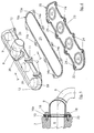
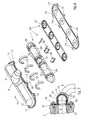
- FIGS. 2 to 6 the exhaust manifold 1 is in each case in various embodiments by exploded views shown.
- the exhaust manifold 1 consists of an exhaust gas collecting housing 9, which the exhaust gases from all exhaust bores 6 a cylinder bank 4 receives, and a sealing device 10.
- the exhaust manifold 9 is surrounded at its entire circumference by a collar 11, in which recesses 12 for the implementation of in Fig. 2 fastening means, not shown, e.g. screws are located. With the fasteners is the exhaust manifold 9 attached to the cylinder head 2.
- the sealing device 10 corresponds in shape to the Cylinder head 2 facing side of the exhaust manifold 9, runs over the entire area between the exhaust manifold 9 and the cylinder head 2 and has accordingly also a collar 13 with recesses 14, whose positions with the positions of the recesses 12 in the collar 11th of the exhaust manifold 9 at least approximately match.
- the sealing device 10 has a plurality of bores 15, their number and their positions with the positions the exhaust bores 6 in the cylinder head 2 at least approximately agree to the flow of the exhaust gas from the exhaust gas holes 6 in the exhaust manifold 9 to ensure.
- the sealing device 10 At its the exhaust manifold 9 facing Side is the sealing device 10 with beads or stampings 16 provided which a gap between generate the cylinder head 2 and the sealing device 10.
- the sealing device 10 may for example consist of a be formed metallic material.
- Fig. 2 can be removed that the exhaust manifold 9 has on its outside a bead 17.
- This bead 17 limits the collar 11 of the exhaust manifold 9 outwardly and increases the strength of the exhaust manifold housing 9.
- the exhaust manifold 9 of a high temperature resistant Material and is capable of facing the sealing device 10 and thus with respect to the cylinder head 2 to perform minor movements, which by the heat input the exhaust gas and the associated expansion the exhaust manifold 9 are caused.
- the exhaust manifold 9 made of multilayer To produce sheets in sandwich construction, whereby the Sound radiation could be reduced.
- Sandwich construction could for example be a layer of Steel and the other layer of aluminum, where also the production of high-temperature resistant exhaust gas collection housings 9 would be possible.
- each catalyst element 39 is assigned to an exhaust gas bore 6 or a cylinder 5, so that in all embodiments four catalyst elements 39 are provided.
- existing catalyst elements 39 are cylindrical and can be upright or be arranged horizontally.
- Drahtgestrickiata held in the exhaust manifold 9 .
- FIG. 4 shows a further embodiment of the exhaust manifold 1, in which in turn the exhaust manifold 9 and the Sealing device 10, but in addition a flange 20th and a further sealing device 10a are provided, to form the exhaust manifold 1.
- the flange 20 is provided with holes 21, the number and positions with the positions of the exhaust holes 6 in the cylinder head 2 at least approximately match.
- the holes 21 are formed in this case round.
- the flange 20 has a circumferential collar 22 and a flange 23, wherein in the collar 22 recesses 24 are introduced whose positions with the positions of Recesses 12 in the exhaust manifold 9 match.
- the sealing device 10a has no in this case Exhaust bores 6 corresponding holes 15, but a over almost the entire length and almost the entire Width of the sealing device 10a extending recess 25. As in FIG. 2, the sealing device 10a but again provided with a collar 13a and recesses 14a. Due to the large recess 25, the seal is done only through the collar 13a of the sealing device 10a.
- Fig. 5 is the attachment of the exhaust manifold 1 in section shown on the cylinder head 2.
- the sealing device 10a between the flange 20 and the Exhaust manifold 9 is arranged.
- the other Sealing device 10 between the cylinder head 2 and the exhaust manifold 9 is the other Sealing device 10, however, in contrast to FIG. 2 and FIG. 3 without stampings 16 and without flanges 17 is executed.
- the Inner contour of the bead 23 of the flange 20 with the outer contour of the exhaust manifold 9 surrounding federal 11th coincides, so that the exhaust gas collecting 9 within the Beading 23 of the flange 20 takes place.
- the exhaust manifold 9, however, has no flanging in this case 17 on. By stamping or spot welding For example, the exhaust gas collecting housing 9 can be preassembled with the flange 20 become.
- Fig. 6 shows a further embodiment of the exhaust manifold 1, which in turn the exhaust manifold 9 and the sealing device 10 has.
- a gas guide channel 26 is arranged, which is in two parts formed with a bottom part 27 and a cover part 28 is.
- the exhaust manifold 9 is as previously with the Covenant 11 and the recesses 12 therein the collar 11 surrounding bead 17 provided.
- the Sealing device 10 also has as described above the collar 13, the recesses 14 and the holes 15.
- the bottom part 27 of a high-temperature resistant Material produced gas guide channel 26 is provided with holes 29 provided whose positions at least approximately the positions of the exhaust bores 6 of the cylinder head. 2 to match. In this way, the exhaust gas in enter the gas guide channel 26.
- baffles 30 are arranged, which the gas flow from the holes 29 to one to the exhaust pipe. 8 leading opening 31, which is in the lid part 28 of the gas guide channel 26 is located.
- the baffles 30 can either with the exhaust manifold 9 or the gas guide channel 26 welded, or from the material of the Bottom part 27 and / or the cover part 28 of the gas guide channel 26 be embossed.
- headband 33 When mounting the exhaust manifold 1 are mounted on on the outside of the lid part 28 Notches 32 headband 33 is placed, which for a Attachment of the gas guide channel 26 provide.
- the headband 33 are arranged such that at Attachment of the exhaust gas collecting housing 9 to the cylinder head 2 by means of the fastening means 18, the headband 33, the gas guide channel 26 hold.
- the tightness of the gas guide channel 26 is ensured by the fact that the bottom part of the 27th very precisely matches with the cover part 28 and this two parts applied by means of the headband 33 Close the force tightly together.
- the bottom part 27 embossed with the cover part 28 or Spot-welded so that a complete pre-assembly possible is.
- the formed as a resilient or damping elements headband 33 may be made of a high temperature resistant material, for example, from a high temperature resistant Knitted wire. Through this type of assembly can dispensed with elaborate welding.
- gas guide channel 26 can also the above-mentioned Arranged catalyst elements 39 for exhaust gas purification and with wire knitting elements, not shown be held in the same.
- the gas guide channel 26 also from one for fluids, in this case for Exhaust gases, permeable material exist.
- This can be, for example solved by a fabric or by a perforated plate be.
- the mass of the gas guide channel 26 is still further reduced and this can so the exhaust less heat revoke.
- the exhaust gas nevertheless strive to flow in the direction of the opening 31 and only a very small part is through the gas guide channel 26 to reach the exhaust manifold 9.
- the air gap 34 can in all versions, in which It also occurs with sound insulating materials, such as e.g. Rock wool, ceramic wool, knitted wire or individual, be filled with each other pressed wire pieces to to achieve a corresponding sound insulation.
- sound insulating materials such as e.g. Rock wool, ceramic wool, knitted wire or individual
- Fig. 8 shows an embodiment of the exhaust manifold 1, which with the embodiment of FIG. 6 approximately coincident.
- the bottom part 27 of the gas guide channel 26 of the flange 20 is provided, which is very similar to the flange 20 of FIG. 4 is trained.
- the holes 21 are in the same oval shaped, i. the diameter of the holes 21st in the longitudinal direction of the flange 20 is larger than the diameter the holes 21 in the transverse direction of the flange 20. This allows a displacement or expansion movement the gas guide channel 26 within the holes 21 due of thermal expansion caused by the exhaust gas temperatures.
- the exhaust gas collection housing 9 Due to the placement of the exhaust manifold 9 in the flange 20 analogous to FIG. 4, the exhaust gas collection housing 9 not provided with the bead 17, but has only the covenant 11 on.
- Fig. 9 it can be seen that between the flange 20 and the Exhaust manifold 9, in turn, the sealing device 10a and between the exhaust gas collecting housing 9 and the cylinder head 2 the sealing device 10 is used.
- the headband 33 and the baffles 30 as in accordance with Fig. 6 and Fig. 7 are provided.
- a further exhaust manifold 1 is shown, the very similar to the exhaust manifold 1 shown in FIG is trained.
- the gas guide channel 26 is provided which, however, consists of several individual channels 35 exists, which in each case with connections 36 to the holes 21 formed in the flange 20 also provided here are.
- the holes 21 have a round cross-section and the terminals 36 are inserted into these holes 21 and optionally welded. Alternatively, there would be others Shapes of the holes 21 are possible, e.g. oval or rectangular, then the connections 36 to these forms of holes 21 would be adapted and in addition a corresponding Sealing would be done.
- the individual channels 35 are interconnected through at each one of the ends of the individual channels 35 intended widenings in which the next single channel 35 inserted and optionally welded, connected.
- retaining rings 37 which bear against the same and the gas guide channel 26th surround.
- an output 38 passes through the Opening 7 in the exhaust gas collecting 9 to the exhaust pipe 8, which is also attached to the exhaust manifold 9 here.
- this gas duct 26 may be one for exhaust gases permeable and high temperature resistant material.
- Fig. 12 shows another exhaust manifold 1, which also has a gas guide channel 26 in its interior. Of the Gas guide channel 26 is facing at its the cylinder head 2 Side provided with a circumferential collar 40, which between the sealing device 10 on its underside and an additional clamping element 41 on its upper side is arranged. The clamping element 41 overlaps the collar 40 partially and covers the same on its entire circumference. In order to achieve a tightness of the exhaust manifold 1, is the clamping element 41 at its the exhaust gas collecting 9th facing side provided with a circumferential sealing pad 42.
- the fastening means 18 are also here provided and clamp with the help of the clamping element 41 the Gas guide channel 26 with the desired force between the Exhaust manifold 9 and the sealing device 10 and the cylinder head 2.
- the gas guide channel 26 perpendicular to the cylinder head plane 2 prevents, with appropriate tightening the
- screws 18 are still one due to heat triggered movement of the gas guide channel 26 in the Level of the cylinder head 2 possible.
- the gas guide channel 26 provided with a circumferential collar 40. This is however, directly between the exhaust manifold 9 and the in This case also provided flange 20 again by means the fastener or screws 18 pinched.
- a circumferential sealing device 43 at the periphery of the collar 40 is a circumferential sealing device 43, and also between the exhaust manifold 9 and the flange 20.
Landscapes
- Engineering & Computer Science (AREA)
- Chemical & Material Sciences (AREA)
- Combustion & Propulsion (AREA)
- Mechanical Engineering (AREA)
- General Engineering & Computer Science (AREA)
- Chemical Kinetics & Catalysis (AREA)
- Health & Medical Sciences (AREA)
- Toxicology (AREA)
- Exhaust Silencers (AREA)
- Exhaust-Gas Circulating Devices (AREA)
Claims (20)
- Collecteur des gaz d'échappement (1), destiné à être fixé sur une tête de cylindre (2) d'un moteur à combustion interne (3) qui comprend au moins un porte-cylindres (4) pourvu d'alésages d'évacuation (6) pour évacuer les gaz d'échappement, avec un carter de collecte des gaz d'échappement (9) pour recevoir des gaz d'échappement provenant de la tête de cylindre (2), avec un dispositif d'étanchéité (10) disposé entre le carter de collecte des gaz d'échappement (9) et la tête de cylindre (2), dans lequel le carter de collecte des gaz d'échappement (9) est pourvu d'évidements (12) à travers lesquels il peut être relié directement, par l'intermédiaire de moyens de fixation (18), avec la tête de cylindre (2), dans lequel le dispositif d'étanchéité (10) est conçu comme une pièce séparée, dans lequel des mouvements dus à l'action de la chaleur sont possibles entre le carter de collecte des gaz d'échappement (9) et le dispositif d'étanchéité (10) ainsi qu'entre le carter de collecte des gaz d'échappement (9) et la tête de cylindre (2), dans lequel un canal de guidage des gaz (26) est disposé à l'intérieur du carter de collecte des gaz d'échappement (9), un interstice (34) se trouvant entre le carter de collecte des gaz d'échappement (9) et le canal de guidage des gaz (26), et dans lequel le canal de guidage des gaz (26) est pourvu, sur son côté orienté vers la tête de cylindre (2), d'un collet circulaire (40) qui, dans l'état monté, est serré au moins indirectement entre le carter de collecte des gaz d'échappement (9) et le dispositif d'étanchéité (10), des mouvements dus à l'action de la chaleur étant possibles entre le canal de guidage des gaz (26) et le dispositif d'étanchéité (10).
- Collecteur des gaz d'échappement selon la revendication 1,
caractérisé en ce que
le dispositif d'étanchéité (10) s'étend sur toute la zone située entre le carter de collecte des gaz d'échappement (9) et la tête de cylindre (2). - Collecteur des gaz d'échappement selon la revendication 1 ou 2,
caractérisé en ce que
le dispositif d'étanchéité (10) comporte des évidements (14) dont les positions correspondent approximativement aux positions des évidements (12) du carter de collecte des gaz d'échappement (9) pour le logement des moyens de fixation (18) qui permettent de relier le carter de collecte des gaz d'échappement (9) à la tête de cylindre (2). - Collecteur des gaz d'échappement selon l'une des revendications 1 à 3,
caractérisé en ce que,
entre le carter de collecte des gaz d'échappement (9) et la tête de cylindre (2), se trouve une bride (20) qui comporte des évidements (24) dont les positions correspondent au moins approximativement aux positions des évidements (12) du carter de collecte des gaz d'échappement (9) pour le logement des moyens de fixation (18) qui permettent de relier le carter de collecte des gaz d'échappement (9) à la tête de cylindre (2). - Collecteur des gaz d'échappement selon la revendication 4,
caractérisé en ce que
le dispositif d'étanchéité (10) est disposé entre la bride (20) et la tête de cylindre (2). - Collecteur des gaz d'échappement selon l'une des revendications 4 ou 5,
caractérisé en ce que
entre le carter de collecte des gaz d'échappement (9) et la bride (20), se trouve un dispositif d'étanchéité (10a). - Collecteur des gaz d'échappement selon l'une des revendications 4 à 6,
caractérisé en ce que
la bride (20) comporte, sur son côté extérieur, un bord rabattu (23) dont le contour interne correspond au moins approximativement au contour externe du collet (11) entourant le carter de collecte des gaz d'échappement (9), des mouvements dus à l'action de la chaleur étant possibles entre le carter de collecte des gaz d'échappement (9) et la bride (20). - Collecteur des gaz d'échappement selon l'une des revendications 1 à 7,
caractérisé en ce que
l'interstice (34) est rempli de matériau d'isolation phonique. - Collecteur des gaz d'échappement selon l'une des revendications 1 à 8,
caractérisé en ce que
le canal de guidage des gaz (26) est constitué d'un matériau perméable aux fluides. - Collecteur des gaz d'échappement selon l'une des revendications 1 à 9,
caractérisé en ce que
le canal de guidage des gaz (26) est conçu en deux parties avec un fond (27) et un couvercle (28), les alésages (29) se trouvant sur le fond (27). - Collecteur des gaz d'échappement selon l'une des revendications 1 à 10,
caractérisé en ce que,
entre le carter de collecte des gaz d'échappement (9) et le canal de guidage des gaz (26) des étriers de maintien (33) sont disposés de telle sorte que, lors de la fixation du carter de collecte des gaz d'échappement (9) sur la tête de cylindre (2) à l'aide des moyens de fixation (18), les étriers de maintien (33) maintiennent le canal de guidage des gaz (26). - Collecteur des gaz d'échappement selon l'une des revendications 1 à 9,
caractérisé en ce que
le canal de guidage des gaz (26) est constitué de plusieurs canaux individuels (35) qui comprennent chacun des raccordements (36) avec des alésages d'évacuation (6) de la tête de cylindre (2). - Collecteur des gaz d'échappement selon l'une des revendications 1 à 12,
caractérisé en ce que
le collet circulaire (40) est serré entre le dispositif d'étanchéité (10) et un élément de serrage (41) qui est pourvu d'un appui d'étanchéité circulaire (42), une bride (20) se trouvant entre le canal de guidage des gaz (26) et la tête de cylindre (2), et le collet circulaire (40) du canal de guidage des gaz (26) étant disposé de manière mobile entre le carter de collecte des gaz d'échappement (9) et la bride (20). - Collecteur des gaz d'échappement selon la revendication 13,
caractérisé en ce que,
entre le collet circulaire (40) du canal de guidage des gaz (26) et la bride (20), se trouve un dispositif d'étanchéité (43). - Collecteur des gaz d'échappement selon la revendication 12 et 13,
caractérisé en ce que
les canaux individuels (35) sont emboítés et, le cas échéant, soudés dans les alésages (21) de la bride (20). - Collecteur des gaz d'échappement selon l'une des revendications 13 à 15,
caractérisé en ce que
la bride (20) est constituée d'un matériau résistant aux hautes températures. - Collecteur des gaz d'échappement selon l'une des revendications 13 à 16,
caractérisé en ce que
la bride (20) est pourvue d'alésages (29) dont les positions correspondent au moins approximativement aux positions des alésages d'évacuation (6) de la tête de cylindre (2), le diamètre des alésages (29) de la bride (20) étant supérieur, dans la direction longitudinale de la bride (20), au diamètre des alésages (29) dans la direction transversale de la bride (20). - Collecteur des gaz d'échappement selon l'une des revendications 1 à 17,
caractérisé en ce que,
dans le carter de collecte des gaz d'échappement (9) ou dans le canal de guidage des gaz (26), se trouvent des tôles de déviation (30) qui sont soudées au carter de collecte des gaz d'échappement (9) ou au canal de guidage des gaz (26). - Collecteur des gaz d'échappement selon l'une des revendications 1 à 18,
caractérisé en ce que,
dans le carter de collecte des gaz d'échappement (9), se trouvent plusieurs éléments catalyseurs individuels (39). - Collecteur des gaz d'échappement selon l'une des revendications 1 à 18,
caractérisé en ce que,
dans le canal de guidage des gaz (26), se trouvent plusieurs éléments catalyseurs individuels (39).
Applications Claiming Priority (5)
| Application Number | Priority Date | Filing Date | Title |
|---|---|---|---|
| DE19936878 | 1999-08-05 | ||
| DE19936878 | 1999-08-05 | ||
| DE10001287 | 2000-01-14 | ||
| DE10001287A DE10001287A1 (de) | 1999-08-05 | 2000-01-14 | Abgaskrümmer |
| PCT/EP2000/006285 WO2001011209A1 (fr) | 1999-08-05 | 2000-07-05 | Collecteur de gaz d'echappement |
Publications (2)
| Publication Number | Publication Date |
|---|---|
| EP1206631A1 EP1206631A1 (fr) | 2002-05-22 |
| EP1206631B1 true EP1206631B1 (fr) | 2005-02-02 |
Family
ID=26003856
Family Applications (1)
| Application Number | Title | Priority Date | Filing Date |
|---|---|---|---|
| EP00945872A Expired - Lifetime EP1206631B1 (fr) | 1999-08-05 | 2000-07-05 | Collecteur de gaz d'echappement |
Country Status (5)
| Country | Link |
|---|---|
| US (1) | US6789386B1 (fr) |
| EP (1) | EP1206631B1 (fr) |
| AT (1) | ATE288539T1 (fr) |
| AU (1) | AU5981900A (fr) |
| WO (1) | WO2001011209A1 (fr) |
Cited By (5)
| Publication number | Priority date | Publication date | Assignee | Title |
|---|---|---|---|---|
| FR2883031A1 (fr) * | 2005-03-08 | 2006-09-15 | Renault Sas | Bride tole d'interface echappement |
| DE102009037520A1 (de) | 2009-08-17 | 2011-04-21 | Poroson Gmbh | Abgaskrümmer |
| EP2921670A2 (fr) | 2014-03-20 | 2015-09-23 | Benteler Automobiltechnik GmbH | Collecteur de gaz d'échappement pour une installation de gaz d'échappement d'un moteur à combustion interne |
| DE102014105656A1 (de) | 2014-04-22 | 2015-10-22 | Benteler Automobiltechnik Gmbh | Abgaskrümmer |
| EP3001004A1 (fr) | 2014-09-26 | 2016-03-30 | Benteler Automobiltechnik GmbH | Collecteur de gaz d'echappement |
Families Citing this family (20)
| Publication number | Priority date | Publication date | Assignee | Title |
|---|---|---|---|---|
| DE10100934C1 (de) * | 2001-01-10 | 2002-02-28 | Freudenberg Carl Kg | Anordnung zur gasdichten Befestigung eines einen Verbindungsflansch aufweisenden Ansaugkrümmers am Zylinderkopf einer Verbrennungskraftmaschine |
| DE50206229D1 (de) * | 2001-01-29 | 2006-05-18 | Hans A Haerle | Abgaskrümmer |
| DE10200638C2 (de) * | 2002-01-10 | 2003-12-11 | Benteler Automobiltechnik Gmbh | Anordnung zur Führung von Abgas aus einem Verbrennungsmotor |
| DE10341868B4 (de) * | 2003-09-09 | 2005-12-22 | Härle, Hans A. | Vorrichtung zur Halterung wenigstens eines Abgasreinigungselements |
| US7272927B2 (en) * | 2003-11-07 | 2007-09-25 | Heinrich Gillet Gmbh | Air gap-insulated exhaust manifold for internal combustion engines |
| DE102004010815A1 (de) * | 2004-03-05 | 2005-09-29 | Benteler Automobiltechnik Gmbh | Anordnung zur Fixierung eines Abgaskrümmers auf dem Zylinderkopf einer Brennkraftmaschine |
| DE102004025407A1 (de) * | 2004-05-24 | 2005-12-22 | Arvin Technologies, Inc., Troy | Krümmer für einen Mehrzylinder-Verbrennungsmotor |
| JP3955291B2 (ja) * | 2004-07-13 | 2007-08-08 | 株式会社共立 | 内燃エンジンの触媒付きマフラー |
| JP2006070705A (ja) * | 2004-08-31 | 2006-03-16 | Honda Motor Co Ltd | 車両用エンジンの排気装置 |
| DE102006012365B4 (de) * | 2006-03-17 | 2014-02-13 | Man Diesel & Turbo Se | Abgasleitungssystem für mehrzylindrige Gas- und Dieselmotoren |
| DE102006033357B4 (de) * | 2006-07-19 | 2009-04-09 | Elringklinger Ag | Einrichtung zur Bildung einer abgedichteten Verschraubung für den Anschluß einer Rohrleitung an einen Ausgang für ein die Einrichtung thermisch belastendes Strömungsmedium |
| DE102007002825B4 (de) * | 2007-01-19 | 2008-12-11 | Audi Ag | Klemmflanschanordnung zum Anschluss einer Auspuffanlage an eine Brennkraftmaschine |
| DE102007062660A1 (de) | 2007-12-24 | 2009-06-25 | J. Eberspächer GmbH & Co. KG | Abgaskrümmer |
| US8356411B2 (en) | 2008-04-07 | 2013-01-22 | Benteler Automotive Corporation | Exhaust manifold with hybrid construction and method |
| DE102009058047A1 (de) * | 2009-12-14 | 2011-06-16 | Benteler Automobiltechnik Gmbh | Abgaskrümmer mit Leitblech |
| WO2012063096A1 (fr) * | 2010-11-08 | 2012-05-18 | Faurecia Systemes D'echappement | Collecteur d'échappement à collerettes minces |
| DE102014103314B4 (de) * | 2014-03-12 | 2018-07-12 | Tenneco Gmbh | Abgasrohrflansch, Gruppenflansch und Abgasanlage |
| US9761781B2 (en) * | 2014-11-29 | 2017-09-12 | Hyundai Motor Company | Thermoelectric generator sleeve for a catalytic converter |
| KR102134108B1 (ko) * | 2016-09-16 | 2020-07-15 | 바르실라 핀랜드 오이 | 고온 물품을 저온 물품에 체결하는 방법 및 고온 물품을 저온 물품에 체결하기 위한 배열체 |
| KR102429002B1 (ko) * | 2016-12-14 | 2022-08-03 | 현대자동차 주식회사 | 엔진의 배기매니폴드 장착 구조 |
Family Cites Families (15)
| Publication number | Priority date | Publication date | Assignee | Title |
|---|---|---|---|---|
| JPS5427620A (en) | 1977-08-01 | 1979-03-01 | Toyota Motor Corp | Installing configuration of exhaust manifold of internal combustion engine |
| GB2097872B (en) * | 1981-05-01 | 1985-04-11 | Nicholson Terence Peter | Improvements relating to gaskets |
| US4537027A (en) | 1983-11-21 | 1985-08-27 | Apx Group, Inc. | Hybrid exhaust manifold |
| DE3534757A1 (de) | 1985-09-28 | 1987-04-09 | Didier Werke Ag | Heissgasfuehrungsbauteil, insbesondere abgasfuehrungsbauteil fuer verbrennungsmotore, und verfahren zu dessen herstellung |
| FR2717224B1 (fr) * | 1994-03-09 | 1996-05-03 | Streit Sa Ets | Collecteur d'échappement pour moteur de véhicules automobiles. |
| JP3388030B2 (ja) * | 1994-07-22 | 2003-03-17 | 本田技研工業株式会社 | 内燃機関の排気装置におけるシール構造 |
| DE4438401C1 (de) | 1994-10-27 | 1996-05-09 | Bayerische Motoren Werke Ag | Vorrichtung zum Einblasen von Luft in ein Abgasrohr |
| US5566548A (en) * | 1994-11-09 | 1996-10-22 | Caterpillar Inc. | Exhaust manifold joint |
| DE19511514C1 (de) * | 1995-03-29 | 1996-08-01 | Daimler Benz Ag | Abgaskrümmer für eine Brennkraftmaschine |
| DE29505660U1 (de) | 1995-04-01 | 1995-06-14 | Gesellschaft für Abgasentgiftungsanlagen mbH, 55262 Heidesheim | Abgassammelrohr mit integrierten Katalysatoren |
| US5692373A (en) * | 1995-08-16 | 1997-12-02 | Northrop Grumman Corporation | Exhaust manifold with integral catalytic converter |
| DE59501301D1 (de) | 1995-09-28 | 1998-02-19 | Benteler Werke Ag | Abgaskrümmer |
| DE19708392A1 (de) | 1997-03-01 | 1998-09-03 | Daimler Benz Ag | Abgaskrümmerflansch für eine Brennkraftmaschine |
| DE59806293D1 (de) | 1997-09-03 | 2002-12-19 | Emitec Emissionstechnologie | Katalysatorträgeranordnung für einen motornahen einbau |
| DE19920822B4 (de) * | 1999-05-06 | 2008-03-27 | Daimler Ag | Anordnung zur Befestigung eines Abgaskrümmers am Zylinderkopf einer Brennkraftmaschine |
-
2000
- 2000-07-05 AT AT00945872T patent/ATE288539T1/de not_active IP Right Cessation
- 2000-07-05 US US10/048,273 patent/US6789386B1/en not_active Expired - Fee Related
- 2000-07-05 EP EP00945872A patent/EP1206631B1/fr not_active Expired - Lifetime
- 2000-07-05 AU AU59819/00A patent/AU5981900A/en not_active Abandoned
- 2000-07-05 WO PCT/EP2000/006285 patent/WO2001011209A1/fr not_active Ceased
Cited By (10)
| Publication number | Priority date | Publication date | Assignee | Title |
|---|---|---|---|---|
| FR2883031A1 (fr) * | 2005-03-08 | 2006-09-15 | Renault Sas | Bride tole d'interface echappement |
| DE102009037520A1 (de) | 2009-08-17 | 2011-04-21 | Poroson Gmbh | Abgaskrümmer |
| EP2921670A2 (fr) | 2014-03-20 | 2015-09-23 | Benteler Automobiltechnik GmbH | Collecteur de gaz d'échappement pour une installation de gaz d'échappement d'un moteur à combustion interne |
| DE102014103809A1 (de) | 2014-03-20 | 2015-12-03 | Benteler Automobiltechnik Gmbh | Abgaskrümmer für eine Abgasanlage eines Verbrennungsmotors |
| DE102014105656A1 (de) | 2014-04-22 | 2015-10-22 | Benteler Automobiltechnik Gmbh | Abgaskrümmer |
| EP2937539A1 (fr) | 2014-04-22 | 2015-10-28 | Benteler Automobiltechnik GmbH | Collecteur de gaz d'échappement |
| DE102014105656B4 (de) | 2014-04-22 | 2017-02-02 | Benteler Automobiltechnik Gmbh | Abgaskrümmer |
| EP3001004A1 (fr) | 2014-09-26 | 2016-03-30 | Benteler Automobiltechnik GmbH | Collecteur de gaz d'echappement |
| DE102014114002A1 (de) | 2014-09-26 | 2016-03-31 | Benteler Automobiltechnik Gmbh | Abgaskrümmer |
| US9689302B2 (en) | 2014-09-26 | 2017-06-27 | Benteler Automobiltechnik Gmbh | Exhaust manifold |
Also Published As
| Publication number | Publication date |
|---|---|
| WO2001011209A1 (fr) | 2001-02-15 |
| EP1206631A1 (fr) | 2002-05-22 |
| US6789386B1 (en) | 2004-09-14 |
| ATE288539T1 (de) | 2005-02-15 |
| AU5981900A (en) | 2001-03-05 |
Similar Documents
| Publication | Publication Date | Title |
|---|---|---|
| EP1206631B1 (fr) | Collecteur de gaz d'echappement | |
| DE69410399T2 (de) | Auspuffkrümmerverbindungskonstruktion mit Luftspalt | |
| EP0582985B1 (fr) | Collecteur d'échappement | |
| DE10125121A1 (de) | Abgaskrümmer | |
| DE19923557B4 (de) | Gebauter luftspaltisolierter Abgaskrümmer einer Abgasanlage eines Kraftfahrzeuges und ein Verfahren zu dessen Herstellung | |
| DE10360645A1 (de) | Auspuffkrümmer | |
| EP1009924B1 (fr) | Ensemble support de catalyseur pour montage dans le compartiment moteur | |
| EP1389267B1 (fr) | Collecteur d'echappement | |
| WO2013000919A1 (fr) | Collecteur modulaire pour véhicule automobile | |
| EP1518043B1 (fr) | Echangeur thermique pour gaz d'echappement et procede de fabrication associe | |
| EP0955453A2 (fr) | Collecteur d'échappement | |
| EP3009623B1 (fr) | Composant pour une installation de gaz d'échappement et fixation pour ce composant | |
| DE4437380A1 (de) | Luftspaltisoliertes Abgasrohr und Verfahren zu seiner Herstellung | |
| EP0849445B1 (fr) | Collecteur d'échappement et procédé pour sa fabrication | |
| DE10001287A1 (de) | Abgaskrümmer | |
| EP0292754B1 (fr) | Bride pour attacher des tuyaux | |
| EP0983425B1 (fr) | Systeme permettant d'eviter les vibrations mecaniques | |
| EP1591636A1 (fr) | Collecteur d'échappement isolé par une couche d'air | |
| EP4098851B1 (fr) | Silencieux | |
| EP0561019B1 (fr) | Dispositif pour le positionnement d'un boîtier intérieur dans le boîtier d'une installation d'échappement pour véhicules | |
| DE69805326T2 (de) | Katalytischer konverter und verfahren zur montage eines konverters | |
| DE9205294U1 (de) | Abgasanlage für Kraftfahrzeuge | |
| DE10144015A1 (de) | Abgasanlage für mehrzylindrige Verbrennungsmotoren | |
| DE19819202A1 (de) | Konischer Wabenkörper und Verfahren zu seiner Herstellung | |
| DE102008048897A1 (de) | Luftspaltisolierter Abgaskrümmer einer Verbrennungskraftmaschine |
Legal Events
| Date | Code | Title | Description |
|---|---|---|---|
| PUAI | Public reference made under article 153(3) epc to a published international application that has entered the european phase |
Free format text: ORIGINAL CODE: 0009012 |
|
| 17P | Request for examination filed |
Effective date: 20020302 |
|
| AX | Request for extension of the european patent |
Free format text: AL;LT;LV;MK;RO;SI |
|
| 17Q | First examination report despatched |
Effective date: 20040115 |
|
| GRAP | Despatch of communication of intention to grant a patent |
Free format text: ORIGINAL CODE: EPIDOSNIGR1 |
|
| GRAS | Grant fee paid |
Free format text: ORIGINAL CODE: EPIDOSNIGR3 |
|
| GRAA | (expected) grant |
Free format text: ORIGINAL CODE: 0009210 |
|
| AK | Designated contracting states |
Kind code of ref document: B1 Designated state(s): AT BE CH CY DE DK ES FI FR GB GR IE IT LI LU MC NL PT SE |
|
| PG25 | Lapsed in a contracting state [announced via postgrant information from national office to epo] |
Ref country code: IT Free format text: LAPSE BECAUSE OF FAILURE TO SUBMIT A TRANSLATION OF THE DESCRIPTION OR TO PAY THE FEE WITHIN THE PRESCRIBED TIME-LIMIT;WARNING: LAPSES OF ITALIAN PATENTS WITH EFFECTIVE DATE BEFORE 2007 MAY HAVE OCCURRED AT ANY TIME BEFORE 2007. THE CORRECT EFFECTIVE DATE MAY BE DIFFERENT FROM THE ONE RECORDED. Effective date: 20050202 Ref country code: FI Free format text: LAPSE BECAUSE OF FAILURE TO SUBMIT A TRANSLATION OF THE DESCRIPTION OR TO PAY THE FEE WITHIN THE PRESCRIBED TIME-LIMIT Effective date: 20050202 Ref country code: NL Free format text: LAPSE BECAUSE OF FAILURE TO SUBMIT A TRANSLATION OF THE DESCRIPTION OR TO PAY THE FEE WITHIN THE PRESCRIBED TIME-LIMIT Effective date: 20050202 Ref country code: IE Free format text: LAPSE BECAUSE OF FAILURE TO SUBMIT A TRANSLATION OF THE DESCRIPTION OR TO PAY THE FEE WITHIN THE PRESCRIBED TIME-LIMIT Effective date: 20050202 Ref country code: GB Free format text: LAPSE BECAUSE OF FAILURE TO SUBMIT A TRANSLATION OF THE DESCRIPTION OR TO PAY THE FEE WITHIN THE PRESCRIBED TIME-LIMIT Effective date: 20050202 Ref country code: FR Free format text: LAPSE BECAUSE OF NON-PAYMENT OF DUE FEES Effective date: 20050202 |
|
| REG | Reference to a national code |
Ref country code: GB Ref legal event code: FG4D Free format text: NOT ENGLISH |
|
| REG | Reference to a national code |
Ref country code: CH Ref legal event code: EP |
|
| REG | Reference to a national code |
Ref country code: IE Ref legal event code: FG4D Free format text: GERMAN |
|
| REF | Corresponds to: |
Ref document number: 50009430 Country of ref document: DE Date of ref document: 20050310 Kind code of ref document: P |
|
| PG25 | Lapsed in a contracting state [announced via postgrant information from national office to epo] |
Ref country code: GR Free format text: LAPSE BECAUSE OF FAILURE TO SUBMIT A TRANSLATION OF THE DESCRIPTION OR TO PAY THE FEE WITHIN THE PRESCRIBED TIME-LIMIT Effective date: 20050502 Ref country code: DK Free format text: LAPSE BECAUSE OF FAILURE TO SUBMIT A TRANSLATION OF THE DESCRIPTION OR TO PAY THE FEE WITHIN THE PRESCRIBED TIME-LIMIT Effective date: 20050502 Ref country code: SE Free format text: LAPSE BECAUSE OF FAILURE TO SUBMIT A TRANSLATION OF THE DESCRIPTION OR TO PAY THE FEE WITHIN THE PRESCRIBED TIME-LIMIT Effective date: 20050502 |
|
| PG25 | Lapsed in a contracting state [announced via postgrant information from national office to epo] |
Ref country code: ES Free format text: LAPSE BECAUSE OF FAILURE TO SUBMIT A TRANSLATION OF THE DESCRIPTION OR TO PAY THE FEE WITHIN THE PRESCRIBED TIME-LIMIT Effective date: 20050513 |
|
| PG25 | Lapsed in a contracting state [announced via postgrant information from national office to epo] |
Ref country code: AT Free format text: LAPSE BECAUSE OF NON-PAYMENT OF DUE FEES Effective date: 20050705 Ref country code: CY Free format text: LAPSE BECAUSE OF FAILURE TO SUBMIT A TRANSLATION OF THE DESCRIPTION OR TO PAY THE FEE WITHIN THE PRESCRIBED TIME-LIMIT Effective date: 20050705 Ref country code: LU Free format text: LAPSE BECAUSE OF NON-PAYMENT OF DUE FEES Effective date: 20050705 |
|
| PG25 | Lapsed in a contracting state [announced via postgrant information from national office to epo] |
Ref country code: BE Free format text: LAPSE BECAUSE OF NON-PAYMENT OF DUE FEES Effective date: 20050731 Ref country code: LI Free format text: LAPSE BECAUSE OF NON-PAYMENT OF DUE FEES Effective date: 20050731 Ref country code: MC Free format text: LAPSE BECAUSE OF NON-PAYMENT OF DUE FEES Effective date: 20050731 Ref country code: CH Free format text: LAPSE BECAUSE OF NON-PAYMENT OF DUE FEES Effective date: 20050731 |
|
| NLV1 | Nl: lapsed or annulled due to failure to fulfill the requirements of art. 29p and 29m of the patents act | ||
| GBV | Gb: ep patent (uk) treated as always having been void in accordance with gb section 77(7)/1977 [no translation filed] |
Effective date: 20050202 |
|
| REG | Reference to a national code |
Ref country code: IE Ref legal event code: FD4D |
|
| PLBE | No opposition filed within time limit |
Free format text: ORIGINAL CODE: 0009261 |
|
| STAA | Information on the status of an ep patent application or granted ep patent |
Free format text: STATUS: NO OPPOSITION FILED WITHIN TIME LIMIT |
|
| 26N | No opposition filed |
Effective date: 20051103 |
|
| REG | Reference to a national code |
Ref country code: CH Ref legal event code: PL |
|
| EN | Fr: translation not filed | ||
| BERE | Be: lapsed |
Owner name: HAERLE, HANS A. Effective date: 20050731 |
|
| PG25 | Lapsed in a contracting state [announced via postgrant information from national office to epo] |
Ref country code: PT Free format text: LAPSE BECAUSE OF NON-PAYMENT OF DUE FEES Effective date: 20050702 |
|
| PGFP | Annual fee paid to national office [announced via postgrant information from national office to epo] |
Ref country code: DE Payment date: 20130823 Year of fee payment: 14 |
|
| REG | Reference to a national code |
Ref country code: DE Ref legal event code: R119 Ref document number: 50009430 Country of ref document: DE |
|
| REG | Reference to a national code |
Ref country code: DE Ref legal event code: R079 Ref document number: 50009430 Country of ref document: DE Free format text: PREVIOUS MAIN CLASS: F01N0007100000 Ipc: F01N0013100000 |
|
| PG25 | Lapsed in a contracting state [announced via postgrant information from national office to epo] |
Ref country code: DE Free format text: LAPSE BECAUSE OF NON-PAYMENT OF DUE FEES Effective date: 20150203 |
|
| REG | Reference to a national code |
Ref country code: DE Ref legal event code: R119 Ref document number: 50009430 Country of ref document: DE Effective date: 20150203 Ref country code: DE Ref legal event code: R079 Ref document number: 50009430 Country of ref document: DE Free format text: PREVIOUS MAIN CLASS: F01N0007100000 Ipc: F01N0013100000 Effective date: 20150325 |