EP1206774B9 - Plattenförmiger optischer datenträger - Google Patents
Plattenförmiger optischer datenträger Download PDFInfo
- Publication number
- EP1206774B9 EP1206774B9 EP00954300A EP00954300A EP1206774B9 EP 1206774 B9 EP1206774 B9 EP 1206774B9 EP 00954300 A EP00954300 A EP 00954300A EP 00954300 A EP00954300 A EP 00954300A EP 1206774 B9 EP1206774 B9 EP 1206774B9
- Authority
- EP
- European Patent Office
- Prior art keywords
- data carrier
- adapter
- thickness
- recess
- opening
- Prior art date
- Legal status (The legal status is an assumption and is not a legal conclusion. Google has not performed a legal analysis and makes no representation as to the accuracy of the status listed.)
- Expired - Lifetime
Links
Images

Classifications
-
- G—PHYSICS
- G11—INFORMATION STORAGE
- G11B—INFORMATION STORAGE BASED ON RELATIVE MOVEMENT BETWEEN RECORD CARRIER AND TRANSDUCER
- G11B7/00—Recording or reproducing by optical means, e.g. recording using a thermal beam of optical radiation by modifying optical properties or the physical structure, reproducing using an optical beam at lower power by sensing optical properties; Record carriers therefor
- G11B7/24—Record carriers characterised by shape, structure or physical properties, or by the selection of the material
- G11B7/24018—Laminated discs
- G11B7/24027—Layers; Shape, structure or physical properties thereof
-
- G—PHYSICS
- G06—COMPUTING OR CALCULATING; COUNTING
- G06K—GRAPHICAL DATA READING; PRESENTATION OF DATA; RECORD CARRIERS; HANDLING RECORD CARRIERS
- G06K19/00—Record carriers for use with machines and with at least a part designed to carry digital markings
- G06K19/04—Record carriers for use with machines and with at least a part designed to carry digital markings characterised by the shape
- G06K19/041—Constructional details
- G06K19/042—Constructional details the record carrier having a form factor of a credit card and including a small sized disc, e.g. a CD or DVD
- G06K19/044—Constructional details the record carrier having a form factor of a credit card and including a small sized disc, e.g. a CD or DVD comprising galvanic contacts for contacting an integrated circuit chip thereon
-
- G—PHYSICS
- G06—COMPUTING OR CALCULATING; COUNTING
- G06K—GRAPHICAL DATA READING; PRESENTATION OF DATA; RECORD CARRIERS; HANDLING RECORD CARRIERS
- G06K19/00—Record carriers for use with machines and with at least a part designed to carry digital markings
- G06K19/06—Record carriers for use with machines and with at least a part designed to carry digital markings characterised by the kind of the digital marking, e.g. shape, nature, code
- G06K19/06009—Record carriers for use with machines and with at least a part designed to carry digital markings characterised by the kind of the digital marking, e.g. shape, nature, code with optically detectable marking
-
- G—PHYSICS
- G06—COMPUTING OR CALCULATING; COUNTING
- G06K—GRAPHICAL DATA READING; PRESENTATION OF DATA; RECORD CARRIERS; HANDLING RECORD CARRIERS
- G06K19/00—Record carriers for use with machines and with at least a part designed to carry digital markings
- G06K19/06—Record carriers for use with machines and with at least a part designed to carry digital markings characterised by the kind of the digital marking, e.g. shape, nature, code
- G06K19/08—Record carriers for use with machines and with at least a part designed to carry digital markings characterised by the kind of the digital marking, e.g. shape, nature, code using markings of different kinds or more than one marking of the same kind in the same record carrier, e.g. one marking being sensed by optical and the other by magnetic means
-
- G—PHYSICS
- G11—INFORMATION STORAGE
- G11B—INFORMATION STORAGE BASED ON RELATIVE MOVEMENT BETWEEN RECORD CARRIER AND TRANSDUCER
- G11B17/00—Guiding record carriers not specifically of filamentary or web form, or of supports therefor
- G11B17/02—Details
- G11B17/04—Feeding or guiding single record carrier to or from transducer unit
- G11B17/0408—Feeding or guiding single record carrier to or from transducer unit of non-disc record carrier, e.g. card
-
- G—PHYSICS
- G11—INFORMATION STORAGE
- G11B—INFORMATION STORAGE BASED ON RELATIVE MOVEMENT BETWEEN RECORD CARRIER AND TRANSDUCER
- G11B25/00—Apparatus characterised by the shape of record carrier employed but not specific to the method of recording or reproducing, e.g. dictating apparatus; Combinations of such apparatus
- G11B25/04—Apparatus characterised by the shape of record carrier employed but not specific to the method of recording or reproducing, e.g. dictating apparatus; Combinations of such apparatus using flat record carriers, e.g. disc, card
-
- G—PHYSICS
- G11—INFORMATION STORAGE
- G11B—INFORMATION STORAGE BASED ON RELATIVE MOVEMENT BETWEEN RECORD CARRIER AND TRANSDUCER
- G11B25/00—Apparatus characterised by the shape of record carrier employed but not specific to the method of recording or reproducing, e.g. dictating apparatus; Combinations of such apparatus
- G11B25/10—Apparatus capable of using record carriers defined in more than one of the sub-groups G11B25/02 - G11B25/08; Adaptor devices therefor
-
- G—PHYSICS
- G11—INFORMATION STORAGE
- G11B—INFORMATION STORAGE BASED ON RELATIVE MOVEMENT BETWEEN RECORD CARRIER AND TRANSDUCER
- G11B33/00—Constructional parts, details or accessories not provided for in the other groups of this subclass
- G11B33/02—Cabinets; Cases; Stands; Disposition of apparatus therein or thereon
- G11B33/04—Cabinets; Cases; Stands; Disposition of apparatus therein or thereon modified to store record carriers
- G11B33/0405—Cabinets; Cases; Stands; Disposition of apparatus therein or thereon modified to store record carriers for storing discs
- G11B33/0411—Single disc boxes
- G11B33/0422—Single disc boxes for discs without cartridge
-
- G—PHYSICS
- G11—INFORMATION STORAGE
- G11B—INFORMATION STORAGE BASED ON RELATIVE MOVEMENT BETWEEN RECORD CARRIER AND TRANSDUCER
- G11B7/00—Recording or reproducing by optical means, e.g. recording using a thermal beam of optical radiation by modifying optical properties or the physical structure, reproducing using an optical beam at lower power by sensing optical properties; Record carriers therefor
- G11B7/24—Record carriers characterised by shape, structure or physical properties, or by the selection of the material
-
- G—PHYSICS
- G11—INFORMATION STORAGE
- G11B—INFORMATION STORAGE BASED ON RELATIVE MOVEMENT BETWEEN RECORD CARRIER AND TRANSDUCER
- G11B7/00—Recording or reproducing by optical means, e.g. recording using a thermal beam of optical radiation by modifying optical properties or the physical structure, reproducing using an optical beam at lower power by sensing optical properties; Record carriers therefor
- G11B7/24—Record carriers characterised by shape, structure or physical properties, or by the selection of the material
- G11B7/24003—Shapes of record carriers other than disc shape
- G11B7/24012—Optical cards
-
- G—PHYSICS
- G11—INFORMATION STORAGE
- G11B—INFORMATION STORAGE BASED ON RELATIVE MOVEMENT BETWEEN RECORD CARRIER AND TRANSDUCER
- G11B7/00—Recording or reproducing by optical means, e.g. recording using a thermal beam of optical radiation by modifying optical properties or the physical structure, reproducing using an optical beam at lower power by sensing optical properties; Record carriers therefor
- G11B7/24—Record carriers characterised by shape, structure or physical properties, or by the selection of the material
- G11B7/2403—Layers; Shape, structure or physical properties thereof
- G11B7/24035—Recording layers
-
- G—PHYSICS
- G11—INFORMATION STORAGE
- G11B—INFORMATION STORAGE BASED ON RELATIVE MOVEMENT BETWEEN RECORD CARRIER AND TRANSDUCER
- G11B7/00—Recording or reproducing by optical means, e.g. recording using a thermal beam of optical radiation by modifying optical properties or the physical structure, reproducing using an optical beam at lower power by sensing optical properties; Record carriers therefor
- G11B7/24—Record carriers characterised by shape, structure or physical properties, or by the selection of the material
- G11B2007/240004—Record carriers characterised by shape, structure or physical properties, or by the selection of the material characterised by the form of the carrier
- G11B2007/240008—Cards
-
- G—PHYSICS
- G11—INFORMATION STORAGE
- G11B—INFORMATION STORAGE BASED ON RELATIVE MOVEMENT BETWEEN RECORD CARRIER AND TRANSDUCER
- G11B2220/00—Record carriers by type
- G11B2220/20—Disc-shaped record carriers
- G11B2220/25—Disc-shaped record carriers characterised in that the disc is based on a specific recording technology
- G11B2220/2537—Optical discs
- G11B2220/2545—CDs
-
- G—PHYSICS
- G11—INFORMATION STORAGE
- G11B—INFORMATION STORAGE BASED ON RELATIVE MOVEMENT BETWEEN RECORD CARRIER AND TRANSDUCER
- G11B2220/00—Record carriers by type
- G11B2220/20—Disc-shaped record carriers
- G11B2220/25—Disc-shaped record carriers characterised in that the disc is based on a specific recording technology
- G11B2220/2537—Optical discs
- G11B2220/2562—DVDs [digital versatile discs]; Digital video discs; MMCDs; HDCDs
Definitions
- the invention relates to a plate-shaped optical data carrier with one for radiation permeable layer and an information recording layer, on the surface of which storage zones are arranged for digital information, the data carrier being a continuous one Has opening for a receiving element of a read and / or write device.
- CD Compact Disc
- CD ROM Compact Disc Read Only Memory
- DVD Digital Versatile Disc
- CD-R on which there is information
- the known data carriers are with their central opening of an adapted receiving element a read-out and / or recording device and rotated offset so that by means of a laser radiation emitting, radially movable reading and / or Write head a data stream from or to the data carrier can be realized.
- the generally known prior art also include so-called CD-ROM cards that Have the thickness of a conventional CD-ROM or DVD, but usually not otherwise standardized check card format.
- the storage area is in such data carriers limited to a circular ring, the maximum in the approximately rectangular disk is writable.
- a disadvantage of these CD-ROM cards is that of conventional ones Credit cards with magnetic strips or electronic chip elements are much larger Thickness. This leads to a greatly reduced elasticity, which is particularly the case with storage the CD-ROM card in a wallet reduces its comfort. Also the space available for standard wallets or wallets is often not sufficient if one Plenty of CD-ROM cards to be accommodated in it. This is also the case for such CD-ROM cards used polycarbonate disadvantageous in terms of handling typical for a card in harsh everyday operations because it is due to the brittleness of the material the low elasticity can quickly lead to breaks or tears in the material.
- DE 297 04 140 U1 describes a CD playback aid, in particular for the multimedia business card as described in DE 296 16 619 U1 is disclosed.
- the outer dimensions of the body of the CD playback aid correspond exactly the standard dimensions of a CD or CD-ROM and has a rectangular cross section continuous interior cutout, the shape of the outer geometry of the multimedia business card equivalent.
- the business card is fixed in the playback aid in that the end faces the business cards are convex in shape and the end faces of the playback aid in the area of the Interior cutout concave.
- plastic materials such as they can be used for both the business card and the playback aid, allowed with one certain effort an insertion of the business card in the cutout, due to a positive and defined connection between the two Components is guaranteed.
- To the process of inserting or releasing the business card To facilitate playback, there are further roundings in the corner areas of the interior cutout available.
- an optically readable digital thin film data carrier is known, the is made of a film-like material and for storage and transport purposes on Carrier sheet is glued on. To read out the data carrier, it is placed on one for the scanning laser beam a playback device permeable carrier placed. The beam path of the laser goes through the carrier where the full or at least partial focus is already of the beam takes place.
- GB 2 059 666 A describes an audio-visual card which is an annular storage part has, which is provided with a helical groove.
- the groove is from the rotating pin a reading device, wherein a conversion into electrical in a purely mechanical manner Signals.
- An optical readout principle is not implemented with this data carrier.
- DE 297 09 648 U1 discloses a business card made from a section of a CD and has, for example, the dimensions of a check card. The accommodation too a chip on one side of the business card is provided. Due to the dimensions of the card and the positioning of the memory chip is a compatibility of the well-known business card with standardized card formats, such as magnetic stripe cards, smart cards and Chip cards, not given.
- the invention has for its object to provide a disk, its handling and storage also meets increased comfort requirements and which is characterized by a variability in the storage principles used in the Awarded data storage.
- Such a data carrier is characterized by its large size due to the reduced thickness Flexibility and therefore a very pleasant handling. Even if a A large number of such data carriers do not give rise to the space problems as they do with conventional ones CD-ROM cards occur.
- the backing layer only has to be dimensioned so thick that the data carrier can be handled and transported without the risk of damage.
- the data carrier is one upstream of the information recording layer, for radiation has permeable layer, this can completely function as the dimensional stability of the Data carrier ensuring carrier layer, so that the thickness of the radiation permeable layer essentially determines the minimum thickness of the disk since the The thickness of the information recording layer is extremely small.
- Thickness reduction is associated with the disadvantage that the disk without further Measures cannot be read out in the currently used CD or DVD players is.
- the invention offers the enormous advantage of creating an optical data carrier, with regard to all its dimensions, in particular its thickness, with data carriers other storage principles (magnetic stripe card, chip card, ...) compatible and therefore "multimedia" can be used.
- the invention corresponds to conventional thickness, length and width Chip cards or magnetic stripe cards.
- the thickness should be according to the current one Standards are approximately 0.8 mm.
- the invention is the first time an optical data carrier presented that is fully compatible in terms of its dimensions and usability to existing formats such as credit card, check card, chip card, and "smart card”.
- a particularly advantageous embodiment of the invention is that the opening is eccentric is arranged and the data carrier with a readable via contact surfaces and / or writable electronic chip element is provided.
- the data carrier according to the invention thus has the further very advantageous property of also fulfilling the function of a chip card.
- the Space requirement for the chip element is created by the eccentric arrangement of the opening for the receiving element.
- the rectangle describing the shape of the data carrier becomes the available storage area not reduced in size because the size of the writable circular ring is opposite a central arrangement of the opening does not change. Due to the eccentric arrangement of the Opening will increase security when using it because it will be obvious to everyone not to use the card without an adapter. Otherwise the card is (also with centric Opening) not in slot drives and not in the usual drawer drawers of PCs use.
- conventional CD cards also have this weakness.
- the radiation-permeable layer advantageously consists of polycarbonate.
- the chip element on the radiation-transmissive Layer facing away from the disk is arranged.
- the data carrier with a magnetic stripe to provide. It makes sense to have both the magnetic stripe and the chip element on the side facing away from the radiation-permeable layer. In this case it is a truly multimedia data carrier.
- a further development of the data carrier according to the invention is that it consists of an annular and the opening having the storage part, the thickness, the length and the Width of a standardized data carrier of the chip card-type carrier part and one there is readable and / or writable chip element via contact surfaces, the Memory part and the chip element can be inserted into the carrier part in such a way that essentially result in flat surfaces of the data carrier.
- annular storage part is easier to produce than another one and secondly, different materials can be used for both parts, to meet the different requirements.
- the storage part is preferably from a high surface hardness polycarbonate, whereas for the carrier part expediently is a flexible material which is less susceptible to breakage, cracking or fatigue, for example made of plastic or cardboard, should be used.
- the storage part have a thickness between 0.5 mm and 0.6 mm has and has an outer diameter which is essentially the width of a standardized Data carrier of the chip card type corresponds to the largest possible storage capacity to achieve the disk.
- the carrier part consists at least partially made of hard cardboard.
- This offers the advantage that the carrier part can be used individually by the user Laser printing can be used to print, for example, as a business card become. After printing, the memory part and possibly the chip element can be attached to it adapted recesses used in the carrier part and for example by gluing be fixed.
- Such business cards offer the advantage over conventional ones that on the one hand, while maintaining the flexibility of conventional chip cards, considerably more information and on the other hand this information can be saved directly at the recipient of the business card can be read into its data processing system, so that a separate and time-consuming there is no need to manually enter this data.
- the invention also proposes an adapter for receiving a data carrier, which is connected to a receiving area is provided, the internal dimensions of which are slightly larger than the external dimensions of the data carrier to be recorded and the one with a central opening is provided, which is coaxial to the opening in the data carrier in its accommodated position is, the sum of the thickness of the data carrier and the thickness of the adapter in the receiving area corresponds to the thickness of a standardized data carrier of the DVD type and that The adapter and data carrier unit can be rotated unbalanced around the central axis of the opening is.
- the adapter is usually not carried by the user, but remains in the readout or write-in device. For a large number of similar data carriers only one adapter required.
- the adapter can e.g. in one piece, for example in Injection molding process or be composed of two disks.
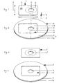
- a data carrier 1 shown in FIG. 1 has the approximately rectangular format of a standard one Chip card, i.e. a length 2 of approx. 85 mm, a width 3 of approx. 54 mm and one Thickness 4 of about 0.8 mm.
- the data carrier 1 is at a location standardized for this purpose with an electronic one Chip element 5 provided for reading and writing digital information.
- the data carrier 1 furthermore has one for radiation on the side that is not visible in FIG. 1 permeable layer with a thickness of about 0.5 mm and one from the lower surface of the Data carrier seen here below arranged information recording layer on the Surface storage zones for digital information are arranged.
- This information recording layer extends over a circular ring area which is shown by the dashed line 6 is limited.
- the data carrier 1 has an eccentric with respect to the rectangle, i.e. outside of the center of gravity, arranged opening 7 with a receiving element, not shown a reading and / or writing device cooperates and therefore in dimensions and shape is standardized. Due to the eccentric opening, the risk is reduced that the data carrier 1 is played without an associated adapter.
- Fig. 2 shows an adapter 8, which is the basic form of a conventional DVD-type data carrier has and has a thickness of 1.2 mm.
- the adapter 8 is made of two cylindrical ones Circular discs 9 and 10 assembled, of which the upper a thickness of about 0.8 mm and the lower one has about 0.4 mm.
- the two circular disks are in the area of their contact surfaces 9 and 10 glued together.
- the lower circular disk 10 in FIG. 2 has a central through opening 11 which is in their diameter corresponds to that of the opening 7 in the data carrier 1.
- the upper Circular disk 9 is provided with a rectangular cutout, which in connection with the an end face 13 of the lower circular disk 10 forming a boundary forms a receiving area 12 defined.
- the data carrier 1 according to FIG. 1 can be inserted into this receiving area 12 in such a way that that on the one hand the opening 7 in the data carrier 1 with the opening 11 in the adapter 8 aligns and on the other hand the surface formed by the permeable layer of the data carrier 1 ends flush with the end face 14 of the upper circular disk 9.
- FIG. 3 shows an alternative data carrier 1 'which, like the data carrier 1 according to FIG. Has width and thickness dimensions that with those of a conventional chip or magnetic stripe card to match.
- an adapter 8 'shown in FIG. 4 is used, which, like the adapter 8 according to FIG Fig. 2 consists of two circular discs 9 'and 10 glued together. While the lower one Circular disc 10 identical to that of the adapter 8 and provided with a central opening 11 ' is, the upper circular disc 9 'has a centrally arranged rectangular cutout on.
- a recording area 12 ' is defined which allows the data carrier 1' to be inserted in such a way that its opening 7 'is aligned with the opening 11 and in conventional ones Readout and / or write-in devices can be used.
- FIGS. 5 to 7 show the structure of the data carrier 1 shown in FIG. 1.
- This consists of a carrier part 16 made of hard cardboard, which in terms of its length, Width and thickness correspond to the respective dimensions of the data carrier 1.
- the carrier part 16 has a cylindrical recess 17, the central axis 15 of which in the longitudinal direction of the support member 16 is symmetrical plane and with respect to the transverse, i.e. perpendicular to this plane of symmetry is arranged offset.
- the recess 17 has a depth 18 of approximately 0.58 mm, from which a residual thickness 19 of the carrier part 16 in the area of Recess 17 of approximately 0.22 mm results.
- the continuous is coaxial to the recess 17 Opening 7 arranged.
- the carrier part 16 has an approximately rectangular, continuous recess 20 provided, in which the chip element 5 can be used according to FIG. 7.
- the storage part 21 shown in FIG. 6 has the same outer diameter and the same thickness 18 of 0.58 mm as the recess 17 in the carrier part 16.
- the storage part 21 has one radiation-permeable layer and an information recording layer arranged thereafter and consists essentially of polycarbonate.
- the storage part according to FIG. 6 is inserted into the recess of the carrier part 16 according to FIG. 5 to hold a data carrier 1 as shown in FIG. 1. So the openings 7 "of the storage part 21 and 7 of the Carrier part 16 congruently one above the other.
- the surface of the storage part 21 in the glued State is flush with the surface of the carrier part 16.
Landscapes
- Engineering & Computer Science (AREA)
- Physics & Mathematics (AREA)
- General Physics & Mathematics (AREA)
- Theoretical Computer Science (AREA)
- Computer Hardware Design (AREA)
- Microelectronics & Electronic Packaging (AREA)
- Optical Record Carriers And Manufacture Thereof (AREA)
- Optical Recording Or Reproduction (AREA)
- Credit Cards Or The Like (AREA)
- Signal Processing For Digital Recording And Reproducing (AREA)
- Optical Communication System (AREA)
- Mobile Radio Communication Systems (AREA)
- Holo Graphy (AREA)
Abstract
Description
- Fig. 1
- einen Datenträger mit exzentrisch angeordneter Öffnung und einem Chipelement sowie einem Magnetstreifen;
- Fig. 2
- einen Adapter zur Aufnahme des Datenträgers gemäß Fig. 1;
- Fig. 3
- einen Datenträger mit zentrisch angeordneter Öffnung;
- Fig. 4
- einen Adapter zur Aufnahme des Datenträgers gemäß Fig. 3;
- Fig. 5
- ein Trägerteil;
- Fig. 6
- ein Speicherteil und
- Fig. 7
- ein Chipelement.
Claims (17)
- Plattenförmiger optischer Datenträger (1,1') in etwa rechteckigem Format, der ein Speicherteil (21) mit einer für Strahlung durchlässigen Schicht und eine im Anschluß daran angeordnete Informationsaufzeichnungsschicht hat, auf deren Oberfläche Speicherzonen für Digitalinformationen angeordnet sind, wobei der Datenträger eine durchgehende Öffnung (7,7',7") für ein Aufnahmeelement einer Auslese- und/oder Einschreibevorrichtung aufweist, dadurch gekennzeichnet, daß die Dicke (4) des Datenträgers gleich der Dicke von ca. 0,8 mm einer standardisierten Chip- oder Magnetstreifenkarte ist und daß das Speicherteil (21) eine Dicke (18) zwischen 0,5 mm und 0,75 mm aufweist.
- Datenträger nach Anspruch 1, dadurch gekennzeichnet, daß er die Länge (2) und die Breite (3) eines standardisierten Datenträgers vom Chipkarten-Typ besitzt.
- Datenträger nach Anspruch 1 oder 2, dadurch gekennzeichnet, daß er aus einem Trägerteil (16) mit einer kreisringförmigen Ausnehmung (17) besteht, in die das Speicherteil (21) derart einsetzbar ist, daß sich im wesentlichen ebene Oberflächen des Datenträgers (1,1') ergeben.
- Datenträger nach einem der Ansprüche 1 bis 3, dadurch gekennzeichnet, daß die Tiefe der Ausnehmung (17) des Trägerteils (16) der Dicke (18) des Speicherteils (21) entspricht.
- Datenträger nach einem der Ansprüche 1 bis 4, dadurch gekennzeichnet, daß das Speicherteil (21) einen Außendurchmesser besitzt, der im wesentlichen einer Breite (3) eines standardisierten Datenträgers vom Chipkarten-Typ entspricht.
- Datenträger nach einem der Ansprüche 1 bis 5, dadurch gekennzeichnet, daß er ein über Kontaktflächen auslesbares Chipelement (5) aufweist, das derart in das Trägerteil (16) einsetzbar ist, daß sich eine im wesentlichen ebene Oberfläche des Datenträgers (1,1') ergibt.
- Datenträger nach einem der Ansprüche 1 bis 6, dadurch gekennzeichnet, daß die Öffnung (7) exzentrisch in dem Datenträger (1) angeordnet ist.
- System aus einem Adapter für eine Auslese- und/oder Einschreibevorrichtung für digitale Daten und einem Datenträger nach einem der Ansprüche 1 bis 7, dadurch gekennzeichnet, daß der Adapter (8,8') aufweist: eine etwa rechteckige Ausnehmung (12,12'), deren Innenabmessungen geringfügig größer sind, als Außenabmessungen eines von ihr aufzunehmenden plattenförmigen Datenträgers (1,1'), eine zentrale Öffnung (11), die koaxial zu einer Öffnung (7,7') des aufzunehmenden Datenträgers (1,1') ist, wobei eine aus dem Adapter (8,8') und dem Datenträger (1,1') zu bildende Einheit um eine Mittelachse (15) der Öffnungen (7,7',11) unwuchtfrei rotierbar ist, wobei die Summe der Dicke des Datenträgers (1,1') und der Dicke des Adapters (8,8') in dessen Ausnehmung (12,12') der Dicke eines standardisierten Datenträgers vom DVD-Typ entspricht.
- System nach Anspruch 8, dadurch gekennzeichnet, daß der plattenförmige Datenträger (1,1') als standardisierte Chip- oder Magnetstreifenkarte in die Ausnehmung (12,12') des Adapters (8,8') einzusetzen ist.
- System nach Anspruch 8 oder 9, dadurch gekennzeichnet, daß der Adapter (8,8') die Grundform eines herkömmlichen Datenträgers vom DVD-Typ besitzt.
- System nach einem der Ansprüche 8 bis 10, dadurch gekennzeichnet, daß der Adapter (8,8') aus zwei Kreisscheiben (9,10) zusammengesetzt ist, von denen die eine (9) eine Dicke von praktisch 0,8 mm und die andere eine Dicke von praktisch 0,4 mm besitzt.
- System nach Anspruch 11, dadurch gekennzeichnet, daß die eine Kreisscheibe (9) mit einem rechteckförmigen Ausschnitt versehen ist, der in Verbindung mit einer eine Begrenzung bildenden Stirnfläche der anderen Kreisscheibe (10) die Ausnehmung (12,12') des Adapters (8,8') bildet.
- System nach einem der Ansprüche 8 bis 12, dadurch gekennzeichnet, daß eine von einer durchlässigen Schicht des Datenträgers (1,1') gebildete Oberfläche mit einer Außenfläche (14) der einen Kreisscheibe (9) des Adapters (8,8') abschließt.
- System nach einem der Ansprüche 8 bis 10, dadurch gekennzeichnet, daß der Adapter (8,8') einstückig im Spritzgießverfahren hergestellt ist.
- System nach einem der Ansprüche 8 bis 14, dadurch gekennzeichnet, daß die einen Datenträger (1) aufnehmende Ausnehmung (12) des Adapters (8,8') exzentrisch in Bezug auf seine zentrale Öffnung (11) angeordnet ist.
- System nach Anspruch 15, dadurch gekennzeichnet, daß die zentrale Öffnung (11) des Adapters (8,8') und eine exzentrisch angeordnete Öffnung (7) eines Datenträgers (1) die gemeinsame Mittelachse (15) aufweisen, um die sich die aus dem Adapter (8) und dem Datenträger (1) gebildete Einheit unwuchtfrei rotieren läßt.
- System nach Anspruch 15 oder 16, dadurch gekennzeichnet, daß die exzentrische Ausnehmung (12) des Adapters (8,8') innerhalb seines Außenumfangs angeordnet ist.
Applications Claiming Priority (5)
| Application Number | Priority Date | Filing Date | Title |
|---|---|---|---|
| DE1999132340 DE19932340A1 (de) | 1999-07-10 | 1999-07-10 | Plattenförmiger optischer Datenträger |
| DE19932340 | 1999-07-10 | ||
| DE29917105U | 1999-09-29 | ||
| DE29917105U DE29917105U1 (de) | 1999-09-29 | 1999-09-29 | Plattenförmiger optischer Datenträger |
| PCT/DE2000/002135 WO2001004905A1 (de) | 1999-07-10 | 2000-07-05 | Plattenförmiger optischer datenträger |
Publications (3)
| Publication Number | Publication Date |
|---|---|
| EP1206774A1 EP1206774A1 (de) | 2002-05-22 |
| EP1206774B1 EP1206774B1 (de) | 2003-12-03 |
| EP1206774B9 true EP1206774B9 (de) | 2004-09-15 |
Family
ID=26054133
Family Applications (1)
| Application Number | Title | Priority Date | Filing Date |
|---|---|---|---|
| EP00954300A Expired - Lifetime EP1206774B9 (de) | 1999-07-10 | 2000-07-05 | Plattenförmiger optischer datenträger |
Country Status (36)
| Country | Link |
|---|---|
| US (1) | US6760280B1 (de) |
| EP (1) | EP1206774B9 (de) |
| JP (1) | JP2003504788A (de) |
| KR (1) | KR20020031155A (de) |
| CN (1) | CN1378693A (de) |
| AP (1) | AP2002002416A0 (de) |
| AT (1) | ATE255765T1 (de) |
| AU (1) | AU6682700A (de) |
| BG (1) | BG106399A (de) |
| BR (1) | BR0012374A (de) |
| CA (1) | CA2373627A1 (de) |
| CU (1) | CU23020A3 (de) |
| CZ (1) | CZ20029A3 (de) |
| DE (2) | DE10081989D2 (de) |
| EA (1) | EA003714B1 (de) |
| EE (1) | EE200200015A (de) |
| ES (1) | ES2211584T3 (de) |
| HR (1) | HRP20020116A2 (de) |
| HU (1) | HUP0201799A2 (de) |
| IL (1) | IL147516A0 (de) |
| LT (1) | LT4950B (de) |
| LV (1) | LV12817B (de) |
| MA (1) | MA25488A1 (de) |
| MX (1) | MXPA02000344A (de) |
| MY (1) | MY133244A (de) |
| NO (1) | NO20020081D0 (de) |
| NZ (1) | NZ517014A (de) |
| PL (1) | PL352124A1 (de) |
| PT (1) | PT1206774E (de) |
| RO (1) | RO121298B1 (de) |
| SI (1) | SI20771A (de) |
| SK (1) | SK52002A3 (de) |
| TR (1) | TR200200042T2 (de) |
| TW (1) | TW470939B (de) |
| WO (1) | WO2001004905A1 (de) |
| YU (1) | YU202A (de) |
Families Citing this family (29)
| Publication number | Priority date | Publication date | Assignee | Title |
|---|---|---|---|---|
| US6510124B1 (en) * | 1997-10-14 | 2003-01-21 | David B. Wood | CD card |
| US7080783B2 (en) * | 2000-09-05 | 2006-07-25 | Digital Castles Llc | Data storage card having both linear and annular data regions |
| GB0025897D0 (en) * | 2000-10-23 | 2000-12-06 | Encore Holdings Ltd | An optically readable carrier and an adapter therefor |
| US7290709B2 (en) * | 2001-04-10 | 2007-11-06 | Erica Tsai | Information card system |
| HK1041776A2 (en) * | 2001-04-24 | 2002-07-12 | Sang Simon Chan Chak | A holder for an optically readable information disc |
| US8403228B2 (en) | 2001-05-15 | 2013-03-26 | Inadam Corporation | Computer readable universal authorization card system and method for using same |
| US7810735B2 (en) | 2001-05-15 | 2010-10-12 | Inadam Corporation | Computer readable universal authorization card system and method for using same |
| US6749114B2 (en) * | 2001-05-15 | 2004-06-15 | Inadam Corporation | Universal authorization card system and method for using same |
| US20050194453A1 (en) * | 2001-07-27 | 2005-09-08 | Storcard, Inc. | Enhanced smart card with rotating storage |
| JP2003196940A (ja) * | 2001-07-27 | 2003-07-11 | Storcard Inc | 回転式記憶装置を備えたスマートカード |
| US6832730B2 (en) | 2001-07-27 | 2004-12-21 | Storcard, Inc. | Smart card with rotating storage |
| US6814286B2 (en) * | 2001-12-17 | 2004-11-09 | Medea International (Taiwan) Corporation | Card for multi-purpose using |
| EP1335374A1 (de) * | 2002-02-08 | 2003-08-13 | Encore Holdings Limited | Datenträger und Adapter dafür |
| US20030174639A1 (en) * | 2002-03-12 | 2003-09-18 | Ritek Corporation | Thin-type optical disc |
| EP1380990A1 (de) * | 2002-07-09 | 2004-01-14 | SCHLUMBERGER Systèmes | Datenträger, welcher in einen weiteren Datenträger anderen Typs eingesetzt ist |
| GB0218858D0 (en) * | 2002-08-14 | 2002-09-25 | Koninkl Philips Electronics Nv | Holder for a storage medium |
| US20040056102A1 (en) * | 2002-09-20 | 2004-03-25 | Yau Sheung Cheung | Multi-Purpose disc |
| US7334733B2 (en) * | 2002-10-16 | 2008-02-26 | Dcard, Inc. | Data access device using rotational head to access data stored in data strips and data arc segments or data circles |
| US7278570B2 (en) * | 2003-09-19 | 2007-10-09 | First Data Corporation | Financial presentation instruments with integrated holder and methods for use |
| FR2867582B1 (fr) * | 2004-03-10 | 2006-05-05 | Michel Koenig | Unite electronique portative comportant dans un microcircuit un processeur numerique a capacite de cryptographie, une me oire flash de grande capacite et un processeur de traitement du signal |
| EP1739601A1 (de) * | 2005-06-24 | 2007-01-03 | Axalto SA | Tragbare Vorrichtung mit zwei Hohlräumen für zwei Datenträger, die in zwei verschiedenen Lesegräten benutzbar sind, und Verfahren zur Herstellung der Vorrichtung |
| ES1061810Y (es) * | 2006-01-03 | 2006-07-16 | Bringue Joel Xavier Aguareles | Articulo de presentacion |
| US20070251999A1 (en) * | 2006-03-21 | 2007-11-01 | Bohlke Edward H Iii | Optical data cards and transactions |
| USD574006S1 (en) | 2006-08-18 | 2008-07-29 | Imx Solutions, Inc. | Optical disc |
| US7885878B2 (en) * | 2008-05-28 | 2011-02-08 | First Data Corporation | Systems and methods of payment account activation |
| US20100050197A1 (en) * | 2008-07-25 | 2010-02-25 | Disctekk, Llc | Optical card |
| MD4141C1 (ro) * | 2011-04-27 | 2012-07-31 | Arcadi ADAMCIUC | Document de identitate |
| US9589161B1 (en) | 2016-05-13 | 2017-03-07 | Kazoo Technology (Hong Kong) Limited | Substrate with electrically conductive patterns that are readable |
| US11526682B2 (en) | 2019-09-11 | 2022-12-13 | Yat Fei CHEUNG | Substrate with electrically conductive pads that are readable by touchscreen device |
Family Cites Families (19)
| Publication number | Priority date | Publication date | Assignee | Title |
|---|---|---|---|---|
| GB2059666B (en) * | 1977-07-13 | 1982-08-04 | Matsushita Electric Industrial Co Ltd | Audi-visual cards |
| NL8503410A (nl) * | 1985-12-11 | 1987-07-01 | Philips Nv | Inrichting voor het overdragen van informatie tussen een elektronische geheugenkaart en een dataverwerkende eenheid. |
| US4916687A (en) * | 1986-05-13 | 1990-04-10 | Canon Kabushiki Kaisha | Apparatus for mounting and rotating an optical card for recording and/or reproducing information |
| US4812633A (en) * | 1988-04-08 | 1989-03-14 | Minnesota Mining And Manufacturing Company | Optical data card |
| US5307338A (en) * | 1988-05-25 | 1994-04-26 | Canon Kabushiki Kaisha | Apparatus for recording and/or reproducing information |
| US5149951A (en) * | 1990-03-05 | 1992-09-22 | Minnesota Mining & Manufacturing Company, A Corporation Of Delaware | Apparatus and method for presenting a data card for data transfer with centrifugal flyweight |
| US5579296A (en) * | 1995-01-18 | 1996-11-26 | Cyberwerks Interactive, L.L.C. | Optically readable thin film digital data storage medium |
| DE29616619U1 (de) | 1996-09-24 | 1996-11-28 | Blaha, Frantisek, Ing., 91356 Kirchehrenbach | Multimediale Visitenkarte |
| DE29704140U1 (de) | 1997-03-07 | 1997-05-22 | Blaha, Frantisek, Ing., 91356 Kirchehrenbach | CD-Abspielhilfe |
| US6400675B1 (en) * | 1997-05-15 | 2002-06-04 | Benjamin James Everidge | Compact disc with a disc tray alignment means |
| US5982736A (en) * | 1997-05-15 | 1999-11-09 | Pierson; Gerald A. | Trading card optical compact disc and methods of using and forming same |
| DE29709648U1 (de) * | 1997-06-03 | 1997-12-11 | Otterstein, Karl, 34132 Kassel | Visitenkarte |
| JPH117751A (ja) * | 1997-06-18 | 1999-01-12 | Oputoromu:Kk | ドライブ一体型ディスク |
| US6016298A (en) * | 1997-06-25 | 2000-01-18 | Adivan High Tech Ag | Calling card |
| US6510124B1 (en) * | 1997-10-14 | 2003-01-21 | David B. Wood | CD card |
| DE29820749U1 (de) * | 1998-11-21 | 1999-02-25 | Ziggel, Carsten, 22085 Hamburg | CD-Visitenkarte |
| EP1043684A1 (de) * | 1999-03-29 | 2000-10-11 | OMD Productions AG | Informationsträger |
| WO2000062249A2 (en) * | 1999-04-07 | 2000-10-19 | Gms-Softmed Sc | Dual smart/optical card |
| TW523717B (en) * | 2000-12-05 | 2003-03-11 | Ritek Corp | Digital business card |
-
2000
- 2000-07-05 WO PCT/DE2000/002135 patent/WO2001004905A1/de not_active Ceased
- 2000-07-05 TR TR2002/00042T patent/TR200200042T2/xx unknown
- 2000-07-05 DE DE10081989T patent/DE10081989D2/de not_active Expired - Fee Related
- 2000-07-05 ES ES00954300T patent/ES2211584T3/es not_active Expired - Lifetime
- 2000-07-05 EA EA200200143A patent/EA003714B1/ru not_active IP Right Cessation
- 2000-07-05 RO ROA200200012A patent/RO121298B1/ro unknown
- 2000-07-05 CZ CZ20029A patent/CZ20029A3/cs unknown
- 2000-07-05 AT AT00954300T patent/ATE255765T1/de not_active IP Right Cessation
- 2000-07-05 US US10/031,202 patent/US6760280B1/en not_active Expired - Fee Related
- 2000-07-05 SI SI200020038A patent/SI20771A/sl not_active IP Right Cessation
- 2000-07-05 IL IL14751600A patent/IL147516A0/xx unknown
- 2000-07-05 SK SK5-2002A patent/SK52002A3/sk unknown
- 2000-07-05 BR BR0012374-9A patent/BR0012374A/pt not_active IP Right Cessation
- 2000-07-05 CN CN00810189A patent/CN1378693A/zh active Pending
- 2000-07-05 PL PL00352124A patent/PL352124A1/xx unknown
- 2000-07-05 DE DE50004666T patent/DE50004666D1/de not_active Expired - Fee Related
- 2000-07-05 AP APAP/P/2002/002416A patent/AP2002002416A0/en unknown
- 2000-07-05 NZ NZ517014A patent/NZ517014A/en unknown
- 2000-07-05 CA CA002373627A patent/CA2373627A1/en not_active Abandoned
- 2000-07-05 EP EP00954300A patent/EP1206774B9/de not_active Expired - Lifetime
- 2000-07-05 JP JP2001509043A patent/JP2003504788A/ja active Pending
- 2000-07-05 YU YU202A patent/YU202A/sh unknown
- 2000-07-05 HU HU0201799A patent/HUP0201799A2/hu unknown
- 2000-07-05 PT PT00954300T patent/PT1206774E/pt unknown
- 2000-07-05 HR HR20020116A patent/HRP20020116A2/hr not_active Application Discontinuation
- 2000-07-05 AU AU66827/00A patent/AU6682700A/en not_active Abandoned
- 2000-07-05 KR KR1020027000324A patent/KR20020031155A/ko not_active Ceased
- 2000-07-05 MX MXPA02000344A patent/MXPA02000344A/es unknown
- 2000-07-05 EE EEP200200015A patent/EE200200015A/xx unknown
- 2000-07-07 MY MYPI20003120 patent/MY133244A/en unknown
- 2000-07-07 TW TW089113468A patent/TW470939B/zh active
-
2002
- 2002-01-08 NO NO20020081A patent/NO20020081D0/no unknown
- 2002-01-09 CU CU20020008A patent/CU23020A3/es unknown
- 2002-01-23 LT LT2002007A patent/LT4950B/lt not_active IP Right Cessation
- 2002-01-30 LV LVP-02-12A patent/LV12817B/xx unknown
- 2002-02-08 BG BG106399A patent/BG106399A/bg unknown
- 2002-02-08 MA MA26514A patent/MA25488A1/fr unknown
Also Published As
Similar Documents
| Publication | Publication Date | Title |
|---|---|---|
| EP1206774B1 (de) | Plattenförmiger optischer datenträger | |
| EP0990220B1 (de) | Visitenkarte mit cd-rom | |
| WO2001069522A9 (de) | Optical-business-card | |
| DE69824521T2 (de) | Zweiseitige hybride dvd-cd-platte | |
| DE29917105U1 (de) | Plattenförmiger optischer Datenträger | |
| DE3714251A1 (de) | Cd-halterungsvorrichtung sowie adapter fuer cds | |
| DE60133604T2 (de) | Verfahren zur Schnellkonfiguration eines optischen Aufzeichnungs- und Wiedergabegeräts und Gerät dazu | |
| DE19932340A1 (de) | Plattenförmiger optischer Datenträger | |
| DE20102719U1 (de) | Chip-Karte, insbesondere SIM-Karte mit Trägerelement | |
| WO2002041304A1 (de) | Plattenförmiger optischer datenträger | |
| EP1194929B1 (de) | Schublade für ein cd-laufwerk | |
| DE19963157A1 (de) | Berührungslos lesbarer, scheibenförmiger Informationsträger | |
| DE29900647U1 (de) | Optisch lesbarer Datenträger | |
| DE10052747A1 (de) | Plattenförmiger optischer Datenträger | |
| DE69605933T2 (de) | Datenspeicherplatte mit geänderter nabe | |
| DE29920125U1 (de) | Bildplatte | |
| DE10008294A1 (de) | Datenspeicher | |
| DE20200052U1 (de) | Mehrzweckkarte | |
| EP2270785A1 (de) | Optischer Datenträger mit Rand | |
| DE20003261U1 (de) | Datenspeicher | |
| DE19912276A1 (de) | Adapter für DVD-Laufwerke | |
| DE10135207A1 (de) | Datenträger Stabilisator | |
| DE19958617A1 (de) | Berührungslos lesbarer, scheibenförmiger Informationsträger | |
| DE20014225U1 (de) | Verpackung für CD und DVD | |
| DE3540140A1 (de) | Verpackung fuer informationstraeger |
Legal Events
| Date | Code | Title | Description |
|---|---|---|---|
| PUAI | Public reference made under article 153(3) epc to a published international application that has entered the european phase |
Free format text: ORIGINAL CODE: 0009012 |
|
| 17P | Request for examination filed |
Effective date: 20020212 |
|
| AX | Request for extension of the european patent |
Free format text: AL;LT;LV;MK;RO;SI |
|
| 17Q | First examination report despatched |
Effective date: 20020718 |
|
| GRAH | Despatch of communication of intention to grant a patent |
Free format text: ORIGINAL CODE: EPIDOS IGRA |
|
| GRAS | Grant fee paid |
Free format text: ORIGINAL CODE: EPIDOSNIGR3 |
|
| GRAA | (expected) grant |
Free format text: ORIGINAL CODE: 0009210 |
|
| AK | Designated contracting states |
Kind code of ref document: B1 Designated state(s): AT BE CH CY DE DK ES FI FR GB GR IE IT LI LU MC NL PT SE |
|
| PG25 | Lapsed in a contracting state [announced via postgrant information from national office to epo] |
Ref country code: IE Free format text: LAPSE BECAUSE OF FAILURE TO SUBMIT A TRANSLATION OF THE DESCRIPTION OR TO PAY THE FEE WITHIN THE PRESCRIBED TIME-LIMIT Effective date: 20031203 Ref country code: CY Free format text: LAPSE BECAUSE OF FAILURE TO SUBMIT A TRANSLATION OF THE DESCRIPTION OR TO PAY THE FEE WITHIN THE PRESCRIBED TIME-LIMIT Effective date: 20031203 Ref country code: FI Free format text: LAPSE BECAUSE OF FAILURE TO SUBMIT A TRANSLATION OF THE DESCRIPTION OR TO PAY THE FEE WITHIN THE PRESCRIBED TIME-LIMIT Effective date: 20031203 |
|
| REG | Reference to a national code |
Ref country code: GB Ref legal event code: FG4D Free format text: NOT ENGLISH |
|
| REG | Reference to a national code |
Ref country code: CH Ref legal event code: EP |
|
| REG | Reference to a national code |
Ref country code: IE Ref legal event code: FG4D Free format text: GERMAN |
|
| REF | Corresponds to: |
Ref document number: 50004666 Country of ref document: DE Date of ref document: 20040115 Kind code of ref document: P |
|
| REG | Reference to a national code |
Ref country code: CH Ref legal event code: NV Representative=s name: E. BLUM & CO. PATENTANWAELTE |
|
| PG25 | Lapsed in a contracting state [announced via postgrant information from national office to epo] |
Ref country code: GR Free format text: LAPSE BECAUSE OF FAILURE TO SUBMIT A TRANSLATION OF THE DESCRIPTION OR TO PAY THE FEE WITHIN THE PRESCRIBED TIME-LIMIT Effective date: 20040303 Ref country code: DK Free format text: LAPSE BECAUSE OF FAILURE TO SUBMIT A TRANSLATION OF THE DESCRIPTION OR TO PAY THE FEE WITHIN THE PRESCRIBED TIME-LIMIT Effective date: 20040303 |
|
| REG | Reference to a national code |
Ref country code: SE Ref legal event code: TRGR |
|
| GBT | Gb: translation of ep patent filed (gb section 77(6)(a)/1977) |
Effective date: 20040318 |
|
| REG | Reference to a national code |
Ref country code: PT Ref legal event code: SC4A Free format text: AVAILABILITY OF NATIONAL TRANSLATION Effective date: 20040303 |
|
| LTIE | Lt: invalidation of european patent or patent extension |
Effective date: 20031203 |
|
| PG25 | Lapsed in a contracting state [announced via postgrant information from national office to epo] |
Ref country code: LU Free format text: LAPSE BECAUSE OF NON-PAYMENT OF DUE FEES Effective date: 20040705 |
|
| REG | Reference to a national code |
Ref country code: ES Ref legal event code: FG2A Ref document number: 2211584 Country of ref document: ES Kind code of ref document: T3 |
|
| REG | Reference to a national code |
Ref country code: IE Ref legal event code: FD4D |
|
| PG25 | Lapsed in a contracting state [announced via postgrant information from national office to epo] |
Ref country code: MC Free format text: LAPSE BECAUSE OF NON-PAYMENT OF DUE FEES Effective date: 20040731 |
|
| ET | Fr: translation filed | ||
| PLBE | No opposition filed within time limit |
Free format text: ORIGINAL CODE: 0009261 |
|
| STAA | Information on the status of an ep patent application or granted ep patent |
Free format text: STATUS: NO OPPOSITION FILED WITHIN TIME LIMIT |
|
| 26N | No opposition filed |
Effective date: 20040906 |
|
| NLR4 | Nl: receipt of corrected translation in the netherlands language at the initiative of the proprietor of the patent | ||
| GBCC | Gb: corrected translation (of claims) filed (gb section 80(3)/1977) | ||
| ET1 | Fr: translation filed ** revision of the translation of the patent or the claims | ||
| PGFP | Annual fee paid to national office [announced via postgrant information from national office to epo] |
Ref country code: PT Payment date: 20050705 Year of fee payment: 6 |
|
| PGFP | Annual fee paid to national office [announced via postgrant information from national office to epo] |
Ref country code: BE Payment date: 20050708 Year of fee payment: 6 Ref country code: CH Payment date: 20050708 Year of fee payment: 6 |
|
| PGFP | Annual fee paid to national office [announced via postgrant information from national office to epo] |
Ref country code: AT Payment date: 20050714 Year of fee payment: 6 |
|
| PGFP | Annual fee paid to national office [announced via postgrant information from national office to epo] |
Ref country code: SE Payment date: 20050727 Year of fee payment: 6 |
|
| PGFP | Annual fee paid to national office [announced via postgrant information from national office to epo] |
Ref country code: NL Payment date: 20050728 Year of fee payment: 6 |
|
| PG25 | Lapsed in a contracting state [announced via postgrant information from national office to epo] |
Ref country code: AT Free format text: LAPSE BECAUSE OF NON-PAYMENT OF DUE FEES Effective date: 20060705 |
|
| PG25 | Lapsed in a contracting state [announced via postgrant information from national office to epo] |
Ref country code: SE Free format text: LAPSE BECAUSE OF NON-PAYMENT OF DUE FEES Effective date: 20060706 |
|
| PG25 | Lapsed in a contracting state [announced via postgrant information from national office to epo] |
Ref country code: CH Free format text: LAPSE BECAUSE OF NON-PAYMENT OF DUE FEES Effective date: 20060731 Ref country code: BE Free format text: LAPSE BECAUSE OF NON-PAYMENT OF DUE FEES Effective date: 20060731 Ref country code: LI Free format text: LAPSE BECAUSE OF NON-PAYMENT OF DUE FEES Effective date: 20060731 |
|
| PG25 | Lapsed in a contracting state [announced via postgrant information from national office to epo] |
Ref country code: PT Free format text: LAPSE BECAUSE OF NON-PAYMENT OF DUE FEES Effective date: 20070105 |
|
| REG | Reference to a national code |
Ref country code: PT Ref legal event code: MM4A Free format text: LAPSE DUE TO NON-PAYMENT OF FEES Effective date: 20070105 |
|
| PG25 | Lapsed in a contracting state [announced via postgrant information from national office to epo] |
Ref country code: NL Free format text: LAPSE BECAUSE OF NON-PAYMENT OF DUE FEES Effective date: 20070201 |
|
| REG | Reference to a national code |
Ref country code: CH Ref legal event code: PL |
|
| EUG | Se: european patent has lapsed | ||
| NLV4 | Nl: lapsed or anulled due to non-payment of the annual fee |
Effective date: 20070201 |
|
| PGFP | Annual fee paid to national office [announced via postgrant information from national office to epo] |
Ref country code: ES Payment date: 20070706 Year of fee payment: 8 |
|
| PGFP | Annual fee paid to national office [announced via postgrant information from national office to epo] |
Ref country code: DE Payment date: 20070927 Year of fee payment: 8 |
|
| BERE | Be: lapsed |
Owner name: *SCHOPPE KARL-HEINZ Effective date: 20060731 |
|
| PGFP | Annual fee paid to national office [announced via postgrant information from national office to epo] |
Ref country code: GB Payment date: 20070704 Year of fee payment: 8 |
|
| PGFP | Annual fee paid to national office [announced via postgrant information from national office to epo] |
Ref country code: IT Payment date: 20070725 Year of fee payment: 8 |
|
| PGFP | Annual fee paid to national office [announced via postgrant information from national office to epo] |
Ref country code: FR Payment date: 20070726 Year of fee payment: 8 |
|
| GBPC | Gb: european patent ceased through non-payment of renewal fee |
Effective date: 20080705 |
|
| PG25 | Lapsed in a contracting state [announced via postgrant information from national office to epo] |
Ref country code: DE Free format text: LAPSE BECAUSE OF NON-PAYMENT OF DUE FEES Effective date: 20090203 |
|
| REG | Reference to a national code |
Ref country code: FR Ref legal event code: ST Effective date: 20090331 |
|
| PG25 | Lapsed in a contracting state [announced via postgrant information from national office to epo] |
Ref country code: GB Free format text: LAPSE BECAUSE OF NON-PAYMENT OF DUE FEES Effective date: 20080705 |
|
| PG25 | Lapsed in a contracting state [announced via postgrant information from national office to epo] |
Ref country code: FR Free format text: LAPSE BECAUSE OF NON-PAYMENT OF DUE FEES Effective date: 20080731 Ref country code: IT Free format text: LAPSE BECAUSE OF NON-PAYMENT OF DUE FEES Effective date: 20080705 |
|
| REG | Reference to a national code |
Ref country code: ES Ref legal event code: FD2A Effective date: 20080707 |
|
| PG25 | Lapsed in a contracting state [announced via postgrant information from national office to epo] |
Ref country code: ES Free format text: LAPSE BECAUSE OF NON-PAYMENT OF DUE FEES Effective date: 20080707 |