EP1207038A2 - Presse - Google Patents
Presse Download PDFInfo
- Publication number
- EP1207038A2 EP1207038A2 EP01126867A EP01126867A EP1207038A2 EP 1207038 A2 EP1207038 A2 EP 1207038A2 EP 01126867 A EP01126867 A EP 01126867A EP 01126867 A EP01126867 A EP 01126867A EP 1207038 A2 EP1207038 A2 EP 1207038A2
- Authority
- EP
- European Patent Office
- Prior art keywords
- crankshaft
- bell crank
- slide
- slider
- frame
- Prior art date
- Legal status (The legal status is an assumption and is not a legal conclusion. Google has not performed a legal analysis and makes no representation as to the accuracy of the status listed.)
- Withdrawn
Links
Images



Classifications
-
- B—PERFORMING OPERATIONS; TRANSPORTING
- B30—PRESSES
- B30B—PRESSES IN GENERAL
- B30B1/00—Presses, using a press ram, characterised by the features of the drive therefor, pressure being transmitted directly, or through simple thrust or tension members only, to the press ram or platen
- B30B1/02—Presses, using a press ram, characterised by the features of the drive therefor, pressure being transmitted directly, or through simple thrust or tension members only, to the press ram or platen by lever mechanism
- B30B1/06—Presses, using a press ram, characterised by the features of the drive therefor, pressure being transmitted directly, or through simple thrust or tension members only, to the press ram or platen by lever mechanism operated by cams, eccentrics, or cranks
-
- B—PERFORMING OPERATIONS; TRANSPORTING
- B30—PRESSES
- B30B—PRESSES IN GENERAL
- B30B15/00—Details of, or accessories for, presses; Auxiliary measures in connection with pressing
- B30B15/0029—Details of, or accessories for, presses; Auxiliary measures in connection with pressing means for adjusting the space between the press slide and the press table, i.e. the shut height
- B30B15/0035—Details of, or accessories for, presses; Auxiliary measures in connection with pressing means for adjusting the space between the press slide and the press table, i.e. the shut height using an adjustable connection between the press drive means and the press slide
-
- B—PERFORMING OPERATIONS; TRANSPORTING
- B30—PRESSES
- B30B—PRESSES IN GENERAL
- B30B15/00—Details of, or accessories for, presses; Auxiliary measures in connection with pressing
- B30B15/0064—Counterbalancing means for movable press elements
Definitions
- the present invention relates to a press machine which converts a rotary motion of a crankshaft supported by a frame into reciprocating motion and transmits the same to a slide.
- Japanese Patent Appln. Publication No. 7-55399 describes a technique of one of press machines capable of adjusting a stroke length of a slide.
- rotary motion of a crankshaft is converted into vertical motion of a slide by a toggle mechanism. Consequently, in comparison with a crank press, the speed of the slide is greatly reduced in the neighborhood of a bottom deed center, as a result of which a stroke of the slide in the neighborhood of the bottom dead center is long, while a stroke of the slide in the neighborhood of a top dead center is short.
- a press machine which converts rotary motion of a crankshaft into vertical motion of a slide by a bell crank mechanism is known (e.g., Japanese Patent Appln. Publication No. 7-121474). In this press machine, however, a stroke length of the slide cannot be changed.
- the press machine comprises a crankshaft rotatably supported on a frame and a power transmission for transmitting rotary motion of the crankshaft to the slide.
- the power transmission includes: a bell crank supported on the frame so as to oscillate about an axis parallel to the rotation axis of the crankshaft; a connection member for connecting the bell crank and the slide so that the slide can perform vertical motion, following oscillating motion of the bell crank; a slider disposed on the frame 'so as to move vertically; a connecting mechanism connected with the crankshaft, the bell crank and the slider so that the bell can oscillate, following the rotation of the crankshaft; and a position adjusting mechanism for adjusting a vertical position of the slider.
- the press machine using the bell crank does not cause a great difference in the stroke of the slide in the neighborhood of the bottom dead center and of the top dead center, thereby enabling acceleration.
- the stroke length of the slide is made variable and enables acceleration.
- the press machine can further comprise a balancer having a balancing weight disposed on the frame so as to move vertically and connected with the bell crank so as to move vertically by shifting its phase with respect to the vertical motion of the slide by 180° .
- a balancer having a balancing weight disposed on the frame so as to move vertically and connected with the bell crank so as to move vertically by shifting its phase with respect to the vertical motion of the slide by 180° .
- the balancing weight which is above the bell crank and the connecting mechanism, is disposed on the frame so as to reciprocate vertically.
- the balancer can be further provided with a connector connected with the bell crank on the lower end side and connected with the balancing weight on the upper end side.
- the bell crank has a T-like shape with three arm portions having an angle to each other such that one arm portion can be connected with the connecting mechanism, another arm portion can be connected with the connection member, and the remaining arm portion can be connected with the balancer.
- the press machine can further comprise one or more weight guides for regulating the vertical motion of the balancing weight to the vertical direction.
- the balancing weight is prevented from reciprocating in the horizontal direction, thereby preventing horizontal vibration of the press machine attributable to reciprocation of the balancing weight.
- the connecting mechanism can include: a linkage having a pair of links connected so as to perform bending and extending motion, following rotation of the crankshaft, one of the links being connected with the crankshaft and the other being connected with the slider; and a connection link for oscillating the bell crank, following the bending and extending motion of the linkage.
- the power transmission further includes: a second bell crank supported by the frame so as to make an oscillating motion about an axis parallel to the rotation axis of the crankshaft; a second connection member for connecting the second bell crank and the slide so that the slide can make vertical motion, following oscillating motion of the bell crank; and a second connecting mechanism connected with the crankshaft, the second bell crank and the slider so that the second bell crank can oscillate, following rotation of the crankshaft.
- the connecting mechanisms can include: a first and a second linkages each having a pair of links connected so as to perform bending and extending motion, following rotation of the crankshaft, one of the links being connected with the crankshaft in common and the other of the links being connected with the slide in common; and a first and a second connection links individually made to correspond to the first and the second linkages and individually made to correspond to the bell crank, so as to oscillate the corresponding bell crank, following bending and extending motion of the corresponding linkage.
- the position adjusting mechanism includes: a bracket pivotally connected with the slider; and a disk-shaped rotor disposed on the frame rotatably about an axis extending in one direction and immovably in the one direction; and a rotary mechanism for rotating the rotor.
- One of the bracket and the rotor can have a male screw hole, while the other can have a male screw portion screwed into the male screw hole. Therefore, since the position of the slider in the one direction can be adjusted finely, an instantaneous speed at each time point of the stroke curve and the vertical motion of the slide can be more finely adjusted depending on the type of press machining.
- the press machine can further comprise a second slider disposed on the frame so as to move vertically and connected with the crankshaft and the connecting mechanism.
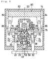
- a press machine 10 comprises a lower frame 12 mounting a drag and an upper frame 14 supported on the lower frame 12.
- a crankshaft 16 is supported on the upper frame 14 so as to rotate about an axis extending horizontally and receives the rotation of a flywheel 18 shown in Fig. 3.
- the flywheel 18 is rotated by a motor (not shown) such as an electric motor.
- a so-called slide 20 supporting a cope is assembled into the lower ends of a pair of connecting rod or plungers 22 which extend through the lower end portion of the upper frame 14 so as to move vertically.
- Both plungers 22 extend upward in parallel from both end portions of the slide 20 and are vertically reciprocated by a power transmission 30 and a bell crank 70 to be described later, following rotation of the crankshaft 16, thereby reciprocating the slide 20 vertically.
- the power transmission 30 includes: a connection 32 connected with the crankshaft 16; a pair of upper sliders 34 disposed at an interval vertically so as to reciprocate vertically and connected with the connection 32 so as to perform pivotal motion; a pair of linkages 36 to be bended or extended, following the reciprocation of both upper sliders 34 and synchronously with each other; a pair of lower sliders 38 disposed on the upper frame 14 so as to be displaced vertically and pivotally connected with both linkages 36; and a position adjusting mechanism 40 for adjusting vertical positions of both lower sliders 38.
- connection 32 is pivotally connected with an eccentric portion of the crankshaft 16 and is vertically reciprocated while oscillating, i.e., swinging with rotation of the crankshaft 16.
- the sliders 34 and 38 are respectively received in guide portions 42 and 44 (see Fig. 3) formed in the upper frame 14 so as to move vertically.
- the upper sliders 34 are vertically reciprocated, following reciprocation of the connection 32, and bend and extend both linkages 36.
- the lower sliders 38 are reciprocated vertically, following the bending and extending motion of both linkages 36.
- Each linkage 36 has a pair of links 36a, 36b.
- the links 36a, 36b of each linkage 36 are connected with each other by a pivot 46 at the lower end portion of the link 36a and the upper end portion of the link 36b so as to bend.
- One of the links 36a of both linkages 36 is connected at its upper end portion with the connection 32 and the upper sliders 34 by a common pivot 48 so as to pivotally move.
- the other of the links 36b of both linkages 36 is connected at its lower end portion with the lower sliders 38 by a common pivot 50 so as to move pivotally.
- the pivots 48, 50 are provided such that their fulcrums are coincident with an axis 52 (see Fig. 2) extending vertically through the center of rotation of the crankshaft 16. It is, however, possible not to dispose the pivots 48, 50 in such a manner.
- link 36a of the linkage 36 is directly connected with the connection 32 and the upper slider 34, it is possible to connect the link 36a of the linkage 36 with only one of the connection 32 and the upper slider 34.
- the position adjusting mechanism 40 is provided with: a forked bracket 54 pivotally connected with both links 36b and the slider 38 by means of the pivot 50; a male screw 56 extending downward from the bracket 54; a worm wheel 58 screwed to the male screw; and a worm screw 60 meshed with the worm wheel 58.
- the male screw 56 may be pivotally connected with both links 36b and the lower slider 38 by means of the pivot 50.
- the male screw 56 is connected with the bracket 54 irrotatably about the axis 52.
- the worm wheel 58 is supported on the support portions 62, 64 of the upper frame 14 irrotatably about the axis 52 and immovably in the vertical direction.
- the shaft portion of the worm screw 60 rotatably extends through the upper frame 14 and has a sprocket 66 at its end portion (see Fig. 6).
- the sprocket 66 is rotated by a rotary mechanism (not shown) such as an electric motor.
- the worm screw 60 When the sprocket 66 is rotated, the worm screw 60 is rotated to rotate the worm wheel 58 meshed with the worm screw 60, whereby the male screw 56 screwed to the worm wheel 58 is moved upward or downward to finally move the lower slider 38 upward or downward. Consequently, the worm wheel 58 acts as a rotor.
- the power transmission 30 also includes: a pair of bell cranks 70 made to individually correspond to the linkages 36 and supported on the frame 14 so as to oscillate about an axis parallel to the rotation axis of the crankshaft 16; a pair of connectors or connection members 72 which are made to correspond individually to the bell cranks 70 and which connect the bell cranks 70 to a slide 20 through plungers 22 so as to have the slide 20 perform vertical motion, following the oscillation of the corresponding bell crank 70; and a pair of connection links 74 made to correspond individually to a set of the linkage 36 and the bell crank 70 to oscillate the corresponding bell crank 70, following bending and extending motion of the corresponding linkage 36.
- One of the sets of the bell crank 70, the connection member 72 and the connection link 74 is made to correspond to one set of plunger 22 and the linkage 36 to be pivotally connected with one set of the plunger 22 and the linkage 36.
- the other set of the bell crank 70, the connection member 72 and the connection link 74 is made to correspond to the other set of the plunger 22 and the linkage 36 to be pivotally connected with the other set of the plunger 22 and the linkage 36.
- Each bell crank 70 has a T-like shape having three arm portions with the same angle to each other (in the illustration, 90° ) and is pivotally assembled at the branching portions of the three arm portions into the bracket 76 mounted on the frame 14.
- Each bell crank 70 having one arm portion connected with the linkage 36 by the connection member 72, is oscillated by the bending and extending motion of the linkage 36.
- the oscillation of each bell crank 70 is transmitted to the slide 20 by the connection link 74 connected with one of the other arm portions so as to move the slide 20 vertically.
- the press machine 10 further comprises a balancer 80 which balances unbalanced force attributable to the vertical motion of the slide 20.
- the balancer 80 includes: a balancing weight 82, the balancing weight 82 which is above the crankshaft 16, both linkages 36 and both bell cranks 70 and disposed on the upper frame 14 so as to move vertically, a plurality of weight guides 84 for restricting reciprocal motion of the balancing weight 82 to the vertical direction; and a pair of connection pieces or connectors 86 which are made to individually correspond to the bell cranks 70.
- Each connector 86 is pivotally connected with the remaining arm portion of the corresponding bell crank 70 at the lower end portion by the horizontal pivot and is pivotally connected with the balancing weight 82 at the upper end portion by the horizontal pivot.
- the reciprocal motion of the balancing weight 82 can be restricted to the vertical direction by using one or more weight guides 84.
- pivots pivotally connecting or supporting a plurality of members such as the pivots 46, 48, 50 extend in the horizontal direction parallel to the rotation axis of the crankshaft 16. Therefore, pivotal motion of members mutually connected by each pivot or members supported by each pivot is motion about an axis extending in the horizontal direction.
- connection 32 since the connection 32 is reciprocally moved in the vertical direction, following rotation of the crankshaft 16, the upper slider 34 is reciprocated in the same direction.
- the lower slider 38 is not moved unless the worm wheel 58 is rotated. Consequently, the pivot 48 acts as a movable side fulcrum of the linkage 36, while the pivot 50 acts as a fixed side fulcrum of the linkage 36.
- both cranks 70 are oscillated, the balancing weight 82 is moved vertically, following the oscillation of both bell cranks 70.
- the reciprocation of the balancing weight 82 at this time is restricted to vertical reciprocation by the weight guides 84 such that, when the slide 20 is moved upward, the balancing weight 82 moves downward, and when the slide 20 is moved downward, the balancing weight 82 is moved upward. This offsets by the balancing weight 82 the unbalanced force attributable to the vertical motion of the slide 20.
- the balancing weight 82 is vertically reciprocated by the bell cranks 70 through the connector 86. Therefore, despite the fact that the balancing weight 82 is connected with the bell cranks 70 which move the slide 20 vertically, horizontal displacement of the balancing weight 82 is surely prevented to prevent horizontal vibration of the press machine attributable to the reciprocal motion of the balancing weight 82.
- the position of the upper slider 34 in the vertical direction does not change, so that, although the angle of bend (the magnitude of the range of bending and extending) of the linkage 36 changes, the range of bending and extending (the position of bending and extending) does not translate vertically. Therefore, the bottom dead center and the stroke length of the slide 20 can be adjusted by rotating the sprocket 66.
- the press machine 10 employs the bell cranks 70 and the position adjusting mechanism 40, there is not caused a large difference in stroke of the slide in the neighborhood of the bottom and top dead centers in comparison with a press machine using a toggle mechanism. Therefore, although acceleration can be realized, the stroke length of the slide 20 can be changed by the position adjusting mechanism 40.
- the amount of movement of the slider 38 with respect to the amount of rotation of the worm screw 60 is very small, so that both position of the bottom dead center and stroke length can be minutely and accurately adjusted.
- another position adjusting mechanism using a lever mechanism or the like may be employed.
- both linkages 36 and two bell cranks 70 are used as mentioned above, the reciprocation of the slide 20 and the balancing weight 82 is stabilized.
- both linkages 36 to be symmetric with respect to the axis 52
- the reciprocation of the slide 20 and the balancing weight 82 is stabilized.
- one set including one of the linkages 36, one of the connection links 74, one of the bell cranks 70 and one of the connectors 86 and the other set including the other of the linkages 36, the other of the connection links 74, the other of the bell cranks 70 and the other of the connectors 86 to be symmetric with respect to the axis 52, and to arrange the slide 20 and the balancing weight 82 with respect to the axis 52.
- the balancer 80 is provided, but it is not always necessary to provide such a balancer 80. Also, instead of moving the slider 38 vertically, it is possible to move the slider 38 in a direction other than the vertical direction, for example, in the horizontal direction.
- the present invention is not limited to the foregoing embodiments.
- the present invention can be variously modified without departing from its spirit.
- only a set of one linkage 36 and one bell crank 70 may be employed.
Landscapes
- Engineering & Computer Science (AREA)
- Mechanical Engineering (AREA)
- Press Drives And Press Lines (AREA)
- Presses And Accessory Devices Thereof (AREA)
Applications Claiming Priority (2)
| Application Number | Priority Date | Filing Date | Title |
|---|---|---|---|
| JP2000345160 | 2000-11-13 | ||
| JP2000345160A JP2002144094A (ja) | 2000-11-13 | 2000-11-13 | プレス機 |
Publications (2)
| Publication Number | Publication Date |
|---|---|
| EP1207038A2 true EP1207038A2 (fr) | 2002-05-22 |
| EP1207038A3 EP1207038A3 (fr) | 2003-01-15 |
Family
ID=18819240
Family Applications (1)
| Application Number | Title | Priority Date | Filing Date |
|---|---|---|---|
| EP01126867A Withdrawn EP1207038A3 (fr) | 2000-11-13 | 2001-11-12 | Presse |
Country Status (2)
| Country | Link |
|---|---|
| EP (1) | EP1207038A3 (fr) |
| JP (1) | JP2002144094A (fr) |
Cited By (5)
| Publication number | Priority date | Publication date | Assignee | Title |
|---|---|---|---|---|
| CN102555254A (zh) * | 2012-02-29 | 2012-07-11 | 西安交通大学 | 一种高速压力机主传动机构 |
| CN108714647A (zh) * | 2018-06-11 | 2018-10-30 | 安陆市华誉金属网机制造有限公司 | 一种冲网机 |
| CN114889185A (zh) * | 2022-05-27 | 2022-08-12 | 东莞市泰基山机械设备有限公司 | 一种多连杆高速冲床 |
| IT202100013343A1 (it) * | 2021-05-24 | 2022-11-24 | Jofa S R L | Pressa elettrica per la caratterizzazione di ammortizzatori di veicoli |
| CN121246314A (zh) * | 2025-12-03 | 2026-01-02 | 苏州斯特智能科技有限公司 | 压力机及传动机构 |
Families Citing this family (5)
| Publication number | Priority date | Publication date | Assignee | Title |
|---|---|---|---|---|
| JP2011041969A (ja) * | 2009-08-24 | 2011-03-03 | Yamada Dobby Co Ltd | プレス機及びプレス機の下死点位置補正方法 |
| CN103112189B (zh) * | 2013-02-02 | 2015-06-10 | 陈浩波 | 一种可限定单次操作的压力机 |
| CN104014691B (zh) * | 2013-03-01 | 2016-03-30 | 东莞市立荣饰品有限公司 | 豌豆夹成型装置 |
| CN103419387B (zh) * | 2013-08-27 | 2015-05-20 | 南京理工大学 | 主被动复合驱动的高速精密数控冲床机构 |
| CN104175593B (zh) * | 2014-09-01 | 2016-04-20 | 广东奥创新能源科技有限公司 | 一种生物质固体成型燃料立式成型机 |
Family Cites Families (6)
| Publication number | Priority date | Publication date | Assignee | Title |
|---|---|---|---|---|
| DE2900901A1 (de) * | 1979-01-11 | 1980-07-17 | Raster Werkzeugmasch Rwm | Exzenterpresse oder -stanze |
| US4276823A (en) * | 1979-01-11 | 1981-07-07 | R W M-Raster-Werkzeugmaschinen Gmbh | Eccentric press |
| JPH07121474B2 (ja) * | 1987-09-14 | 1995-12-25 | 京利工業株式会社 | プレス機 |
| JPH0755399B2 (ja) * | 1992-10-05 | 1995-06-14 | 株式会社山田ドビー | プレス機の動力伝達装置 |
| JP2649318B2 (ja) * | 1993-11-11 | 1997-09-03 | 株式会社山田ドビー | プレス機 |
| JP4291896B2 (ja) * | 1998-06-10 | 2009-07-08 | 株式会社山田ドビー | プレス機 |
-
2000
- 2000-11-13 JP JP2000345160A patent/JP2002144094A/ja active Pending
-
2001
- 2001-11-12 EP EP01126867A patent/EP1207038A3/fr not_active Withdrawn
Cited By (7)
| Publication number | Priority date | Publication date | Assignee | Title |
|---|---|---|---|---|
| CN102555254A (zh) * | 2012-02-29 | 2012-07-11 | 西安交通大学 | 一种高速压力机主传动机构 |
| CN102555254B (zh) * | 2012-02-29 | 2014-04-23 | 西安交通大学 | 一种高速压力机主传动机构 |
| CN108714647A (zh) * | 2018-06-11 | 2018-10-30 | 安陆市华誉金属网机制造有限公司 | 一种冲网机 |
| CN108714647B (zh) * | 2018-06-11 | 2023-11-28 | 安陆市华誉金属网机制造有限公司 | 一种冲网机 |
| IT202100013343A1 (it) * | 2021-05-24 | 2022-11-24 | Jofa S R L | Pressa elettrica per la caratterizzazione di ammortizzatori di veicoli |
| CN114889185A (zh) * | 2022-05-27 | 2022-08-12 | 东莞市泰基山机械设备有限公司 | 一种多连杆高速冲床 |
| CN121246314A (zh) * | 2025-12-03 | 2026-01-02 | 苏州斯特智能科技有限公司 | 压力机及传动机构 |
Also Published As
| Publication number | Publication date |
|---|---|
| JP2002144094A (ja) | 2002-05-21 |
| EP1207038A3 (fr) | 2003-01-15 |
Similar Documents
| Publication | Publication Date | Title |
|---|---|---|
| US5687645A (en) | Mechanical pressing machine | |
| JPH0755399B2 (ja) | プレス機の動力伝達装置 | |
| US5052257A (en) | Mass forces balancing apparatus in a machine having a crank shaft drive, specifically a punching machine | |
| US5467706A (en) | Mechanical pressing machine with dynamic balancing device | |
| EP0972630A2 (fr) | Presse | |
| EP1162057B1 (fr) | Dispositif d'entraînement du coulisseau pour une presse | |
| EP1175993A2 (fr) | Dispositif d'entraínement pour presse | |
| JP2002144094A (ja) | プレス機 | |
| EP1207039B1 (fr) | Presse | |
| JP2649318B2 (ja) | プレス機 | |
| EP1223027B1 (fr) | Transmission de puissance pour presse | |
| JP3889930B2 (ja) | プレス機の動力伝達装置 | |
| JPH11245096A (ja) | スライダリンクプレス | |
| JP4291896B2 (ja) | プレス機 | |
| JP2003080397A (ja) | プレス機 | |
| JP2002066797A (ja) | プレス機械 | |
| US6629494B2 (en) | Slide driving device for a press machine | |
| JPH10109194A (ja) | リンクを用いた機械プレスのスライド駆動装置 | |
| US5605096A (en) | Mechanical pressing machine with dynamic balancing device | |
| JPH10109192A (ja) | リンクを用いた機械プレスのスライド駆動装置 | |
| JP3660728B2 (ja) | プレス機 | |
| JP3866529B2 (ja) | クランクプレスの駆動装置 | |
| JP2003080398A (ja) | プレス機 | |
| JP2000317688A (ja) | プレス機 | |
| JP2000288790A (ja) | プレス機 |
Legal Events
| Date | Code | Title | Description |
|---|---|---|---|
| PUAI | Public reference made under article 153(3) epc to a published international application that has entered the european phase |
Free format text: ORIGINAL CODE: 0009012 |
|
| AX | Request for extension of the european patent |
Free format text: AL;LT;LV;MK;RO;SI |
|
| PUAL | Search report despatched |
Free format text: ORIGINAL CODE: 0009013 |
|
| AK | Designated contracting states |
Kind code of ref document: A3 Designated state(s): AT BE CH CY DE DK ES FI FR GB GR IE IT LI LU MC NL PT SE TR |
|
| AX | Request for extension of the european patent |
Free format text: AL;LT;LV;MK;RO;SI |
|
| 17P | Request for examination filed |
Effective date: 20030227 |
|
| AKX | Designation fees paid |
Designated state(s): CH DE LI |
|
| 17Q | First examination report despatched |
Effective date: 20041214 |
|
| 17Q | First examination report despatched |
Effective date: 20041214 |
|
| STAA | Information on the status of an ep patent application or granted ep patent |
Free format text: STATUS: THE APPLICATION IS DEEMED TO BE WITHDRAWN |
|
| 18D | Application deemed to be withdrawn |
Effective date: 20061031 |