EP1207108A1 - Füllstutzen zum Füllen mit zwei Flüssigkeits- oder Gasprodukten in Füllmaschinen - Google Patents
Füllstutzen zum Füllen mit zwei Flüssigkeits- oder Gasprodukten in Füllmaschinen Download PDFInfo
- Publication number
- EP1207108A1 EP1207108A1 EP01204303A EP01204303A EP1207108A1 EP 1207108 A1 EP1207108 A1 EP 1207108A1 EP 01204303 A EP01204303 A EP 01204303A EP 01204303 A EP01204303 A EP 01204303A EP 1207108 A1 EP1207108 A1 EP 1207108A1
- Authority
- EP
- European Patent Office
- Prior art keywords
- opening
- hollow body
- shutter element
- container
- shutter
- Prior art date
- Legal status (The legal status is an assumption and is not a legal conclusion. Google has not performed a legal analysis and makes no representation as to the accuracy of the status listed.)
- Withdrawn
Links
- 239000007788 liquid Substances 0.000 title claims abstract description 42
- 239000000945 filler Substances 0.000 title claims abstract description 15
- 239000007789 gas Substances 0.000 claims description 21
- 238000006073 displacement reaction Methods 0.000 claims description 2
- 230000009977 dual effect Effects 0.000 claims description 2
- 230000000750 progressive effect Effects 0.000 description 2
- 230000003068 static effect Effects 0.000 description 2
- 239000003990 capacitor Substances 0.000 description 1
- 239000012530 fluid Substances 0.000 description 1
- 239000006260 foam Substances 0.000 description 1
- 238000009434 installation Methods 0.000 description 1
- 239000000463 material Substances 0.000 description 1
- 230000004048 modification Effects 0.000 description 1
- 238000012986 modification Methods 0.000 description 1
- 239000000047 product Substances 0.000 description 1
- 230000001105 regulatory effect Effects 0.000 description 1
- 230000001131 transforming effect Effects 0.000 description 1
Images



Classifications
-
- B—PERFORMING OPERATIONS; TRANSPORTING
- B67—OPENING, CLOSING OR CLEANING BOTTLES, JARS OR SIMILAR CONTAINERS; LIQUID HANDLING
- B67C—CLEANING, FILLING WITH LIQUIDS OR SEMILIQUIDS, OR EMPTYING, OF BOTTLES, JARS, CANS, CASKS, BARRELS, OR SIMILAR CONTAINERS, NOT OTHERWISE PROVIDED FOR; FUNNELS
- B67C3/00—Bottling liquids or semiliquids; Filling jars or cans with liquids or semiliquids using bottling or like apparatus; Filling casks or barrels with liquids or semiliquids
- B67C3/02—Bottling liquids or semiliquids; Filling jars or cans with liquids or semiliquids using bottling or like apparatus
- B67C3/22—Details
- B67C3/28—Flow-control devices, e.g. using valves
-
- B—PERFORMING OPERATIONS; TRANSPORTING
- B65—CONVEYING; PACKING; STORING; HANDLING THIN OR FILAMENTARY MATERIAL
- B65B—MACHINES, APPARATUS OR DEVICES FOR, OR METHODS OF, PACKAGING ARTICLES OR MATERIALS; UNPACKING
- B65B39/00—Nozzles, funnels or guides for introducing articles or materials into containers or wrappers
- B65B39/001—Nozzles, funnels or guides for introducing articles or materials into containers or wrappers with flow cut-off means, e.g. valves
- B65B39/004—Nozzles, funnels or guides for introducing articles or materials into containers or wrappers with flow cut-off means, e.g. valves moving linearly
-
- B—PERFORMING OPERATIONS; TRANSPORTING
- B67—OPENING, CLOSING OR CLEANING BOTTLES, JARS OR SIMILAR CONTAINERS; LIQUID HANDLING
- B67C—CLEANING, FILLING WITH LIQUIDS OR SEMILIQUIDS, OR EMPTYING, OF BOTTLES, JARS, CANS, CASKS, BARRELS, OR SIMILAR CONTAINERS, NOT OTHERWISE PROVIDED FOR; FUNNELS
- B67C3/00—Bottling liquids or semiliquids; Filling jars or cans with liquids or semiliquids using bottling or like apparatus; Filling casks or barrels with liquids or semiliquids
- B67C3/02—Bottling liquids or semiliquids; Filling jars or cans with liquids or semiliquids using bottling or like apparatus
- B67C3/023—Filling multiple liquids in a container
- B67C3/026—Filling the liquids simultaneously
Definitions
- the present invention refers to a nozzle for filling operations with two liquid and/or gas products for filler machines, in particular both static and rotary filler machines.
- the plugging shutter as it moves away from the outlet, frees the passage and can allow the liquid to escape at a greater flow rate the further the pin is from the outlet.
- This arrangement of parts has the great limitation that it only allows one single product to be dispensed, for example a liquid, at any one time. In such a way if two liquids or a liquid and a gas or other need to be dispensed inside a container, one has to foresee two successive stations for the successive and separate feeding of them in the same container.
- a purpose of the present invention is that of realising a nozzle for filling operations with two liquid and/or gas products for filler machines which solves all of the technical problems outlined previously.
- Another purpose is that of simplifying down to the minimum the apparatus and the devices connected to the interception and the control of the nozzle for filling a single container with liquid and/or gas products.
- Yet another purpose is that of easing, improving and making as fast as possible the operations connected to the filling of a container with two liquid and/or gas products.
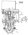
- a nozzle for filling operations with two liquid and/or gas products for filler machines is shown, indicated as a whole with 10, and is associated with a first 12 and with a second 11 system for feeding identical or different products, in the form of a liquid and/or a gas.
- the nozzle 10 either alone or acting together with many similar units can be arranged on a filler machine of the fixed or rotary swivel type.
- the feeding systems 12 and 11 are arranged with one above and one along the side of a support structure 13 for carrying the nozzle 10.
- a base opening 14 of the first feeding system 12 is aligned with a mouth 15, of the tubular type, formed in the support structure 13 and facing downwards so as to insert into a hollow body 16 or short duct which constitutes the most outer part of the nozzle 10.
- the hollow body 16 also has a tubular form and is suitable for at least partially surrounding the mouth 15 to form a seal through a gasket 17, attached to the outside of the mouth 15 and capable of sliding on the hollow body 16.
- the presence of the gasket guarantees the seal against the leaking of the liquid and/or gas, also in the case in which the machine's first feeding system 12 is pressurised.
- the hollow body 16 has a first opening or mouth 18 for the outlet or discharge of the first liquid which can receive additional systems for conveying and slowing the fluid, such as nets or other which are not shown in the figures, for example screwed or locked in another way on the hollow body 16.
- An end portion 16a which can be connected with the junction 16b which allows the size of the opening 18 to be varied, forms part of the body 16.
- a first shutter element 21 or outer shutter, for example ogive-shaped, is fixedly connected with the mouth 15 or with the support structure 13, supported by a. spoke 20 radially turned towards the inside of the mouth 15.
- a spoke 20 for example, is likely to be one of three fins arranged at 120° and supporting the first shutter element 21.
- a passage 22 which can be used for feeding a second filling product, that being a liquid and/or gas, in an axial hollow chamber 19 of the first shutter element 21 and then in the container (not shown).
- the hollow body 16 can be moved between at least one engagement position, wherein the first opening 18 is engaged and closed by the first shutter element 21, and a disengagement position wherein the first product flows from such an opening 18, of variable size, into the aforementioned container, which is not shown.
- cylindrical ends 25 of a pair of arms (only partially shown for example in figure 1) of a control fork 27 are put on pivoting means or supports, not shown.
- the control fork 27 is centrally pivoted at 28 to a downwards extension 29 of the support structure 13 and on the other side extends as a second fork end 30, which is partially shown.
- This second end 30 is bound to the other end through a pin 31 to an end eyelet 32 of an actuator group or element, wholly indicated with 33.
- the actuator element 33 is bound at its other end through a further pin 34 to the support structure 13.
- the actuator element 33 in the example, comprises a pair of pneumatic cylinders 35 and 36 whose stroke, individual or combined, allows up to three different degrees of opening of the nozzle to be realised. In such a way it is possible to realise the mass rough filling of the container, through the two cylinders 35 and 36 actuated simultaneously, and the finishing off of the filling, through cylinder 36 alone.
- such an actuator element 33 can consist of an electric group with a brushless motor, a stepper motor, a proportional pneumatic cylinder or another device. In such a way it is possible to obtain an opening of the nozzle which can be predetermined as one wishes between totally closed and completely open, instead of only the three levels which can be obtained with the two pneumatic cylinders indicated.
- a safety spring 37 which has the function of closing the nozzle when there is no compressed air, has been foreseen. In such an eventuality the spring 37 overcomes the pressure of the liquid, the weight of the devices and the friction forces, making the nozzle close.
- a screwable regulator device with a nut and counternut, indicated with 40, arranged between the two cylinders 35 and 36 capable of allowing the stroke of the cylinder 36 to be partially reduced is foreseen.
- the first shutter element 21 comprises the axial hollow chamber 19 inside of it which, at its end facing towards the first opening 18, is also equipped with a second opening 38, coaxial with the first opening 18 and of a smaller size.
- a rod 39 which foresees at its end a second shutter element 41, also ogive-shaped, capable of closing the second opening 38, can be moved in the axial hollow chamber 19.
- annular passages for the two outlet liquid and/or gas products are defined.
- the rod 39 has a smaller diameter so as not to clog up the inside of the hollow chamber 19 and to allow the second product, coming from the second product reservoir 11, to pass.
- the rod 39 extends for an upper portion 39a thereof which is arranged in a tubular body 42 in which it slides guided and sealed thanks to the presence of gaskets 43.
- the rod 39 and 39a is connected to a piston 44 arranged in a cylinder 45 which extends upwards from the body of the first shutter element so as to define a channel 46 through the inside of it and between the tubular mouth 15 and the hollow body 16 for the passage of the first product coming from the first reservoir 12.
- a spring 50 is also foreseen.
- This elastic element 50 reacting between the piston 44 and the upper inner surface of the cylinder 45, usually keeps the piston 44, the rod 39a and 39 and thus the second shutter element 41 in the closed position for the second opening 38.
- this double-feeding arrangement 47, 48 of the cylinder 45 with an inner spring 50 allows an opening of the nozzle feeding the second product which can be predetermined as one wishes between totally closed and totally open, instead of a fixed number of only two or three levels, known up to now.
- a nozzle for filling operations with two liquid and/or gas products for filler machines is realised in a single position for filling the container according to steps which are predetermined by the user.
- a nozzle according to the invention which can be defined as a double concentric valve, or rather a double concentric shutter nozzle.
- a first product, such as a liquid, contained in the reservoir 12 must first be fed in a quantity A to occupy a considerable portion of the container, for example 80%.
- the actuator element 33 is actuated starting from a completely closed position illustrated in figure 1.
- the second product arriving from the reservoir 11 and passing through the passage 22 and through the piping 22a, flows into the hollow chamber 19 of the first shutter element 21 and from there into the underlying container.
- the dispensing takes place in both cases according to the axial direction of the nozzle with a saving of space and of costs, avoiding the use of two nozzles, one for each product.
- the quantity and the filling times of both the liquid or gas products can be chosen as desired. All of these advantages can also be used not just in a fixed position, but also, in the case of rotation, in a filler of the rotary type.
- the outlet opening 18 of the first liquid is not fixed, but moves with respect to the feeding system 12 and to the container to be filled (not shown) by an amount which is greater the bigger the size of the opening which is left open by the nozzle's shutter.
- Figure 4 shows how the second shutter element 41 can have a pointed form extending from the rod 39 thanks to the fact that the first shutter element 21 has an extremely pointed form with a restricted outlet opening 38. Such an extension leads to a lower dispensing of the second product. It is possible to have a combination as desired of the diameters of the openings 18 and 38, replacing the end elements 16a, 21 and 41.
- the presence of the gaskets 17 and 43 interposed between the fixed inner mouth 15 and the mobile outer part 16 as well as between the extension of the rod 39a and the fixed tubular body 42 inside the mouth 15 is such as to guarantee the seal against the leaking of liquids and/or gases, also in the case in which the feeding systems of the machine are pressurised.
- this nozzle allows there to be, as well as a feeding of two products, also a feeding without foam due the differing liquid levels and possibly a sucking in through the opening 18, transforming the feeding system 12 into a sucking system.
- nozzle of the present invention is susceptible to numerous modifications and variants, all covered by the same invention.
- the materials used, as well as their sizes and the components, can be whatever according to the technical requirements.
Landscapes
- Engineering & Computer Science (AREA)
- Mechanical Engineering (AREA)
- Supply Of Fluid Materials To The Packaging Location (AREA)
- Filling Of Jars Or Cans And Processes For Cleaning And Sealing Jars (AREA)
- Basic Packing Technique (AREA)
- Vacuum Packaging (AREA)
- Feeding, Discharge, Calcimining, Fusing, And Gas-Generation Devices (AREA)
Applications Claiming Priority (2)
| Application Number | Priority Date | Filing Date | Title |
|---|---|---|---|
| ITMI002482 | 2000-11-17 | ||
| IT2000MI002482A IT1320083B1 (it) | 2000-11-17 | 2000-11-17 | Ugello di riempimento di due prodotti liquidi e/o gassosi per macchineriempitrici. |
Publications (1)
| Publication Number | Publication Date |
|---|---|
| EP1207108A1 true EP1207108A1 (de) | 2002-05-22 |
Family
ID=11446122
Family Applications (1)
| Application Number | Title | Priority Date | Filing Date |
|---|---|---|---|
| EP01204303A Withdrawn EP1207108A1 (de) | 2000-11-17 | 2001-11-12 | Füllstutzen zum Füllen mit zwei Flüssigkeits- oder Gasprodukten in Füllmaschinen |
Country Status (6)
| Country | Link |
|---|---|
| US (1) | US6546970B2 (de) |
| EP (1) | EP1207108A1 (de) |
| CN (1) | CN1358574A (de) |
| BR (1) | BR0105232A (de) |
| CA (1) | CA2363327A1 (de) |
| IT (1) | IT1320083B1 (de) |
Cited By (11)
| Publication number | Priority date | Publication date | Assignee | Title |
|---|---|---|---|---|
| EP1310454B1 (de) * | 2001-11-09 | 2005-12-28 | Sig Simonazzi S.P.A. | Abfüllventil für Abfüllmaschine |
| WO2006091159A1 (en) * | 2005-02-23 | 2006-08-31 | Norden Machinery Ab | Filling nozzle |
| EP1731478A1 (de) * | 2005-06-08 | 2006-12-13 | AZIONARIA COSTRUZIONI MACCHINE AUTOMATICHE-A.C.M.A.-S.p.A. | Maschine zum Füllen von Behältern mit Flüssigkeiten oder Pulvern |
| WO2007039074A1 (en) * | 2005-09-20 | 2007-04-12 | Weightpack S.P.A. | Machine for filling containers |
| WO2009013523A1 (en) * | 2007-07-24 | 2009-01-29 | Jens Termansen | Fluid control arrangement |
| WO2009129937A1 (de) * | 2008-04-22 | 2009-10-29 | Khs Ag | Verfahren sowie füllsystem zum füllen von flaschen oder dergleichen behältern mit einem flüssigen füllgut sowie in behälter abgefültes füllgut |
| WO2010017888A1 (de) * | 2008-08-12 | 2010-02-18 | Khs Ag | Verfahren zum abfüllen eines aus wenigstens einer ersten und einer zweiten komponente bestehenden füllgutes |
| DE102009037780A1 (de) * | 2009-08-18 | 2011-03-03 | Khs Gmbh | Füllelement sowie Füllsystem oder Füllmaschine mit einer Vielzahl von Füllelementen |
| WO2011092188A1 (de) * | 2010-01-27 | 2011-08-04 | Elopak Systems Ag | Dosiervorrichtung und dosierverfahren für flüssigkeiten |
| US8020590B2 (en) | 2004-11-25 | 2011-09-20 | Tgm Tecnomachines S.R.L. | Nozzle for filling a container with at least two viscous materials |
| EP2650253A1 (de) * | 2012-04-11 | 2013-10-16 | Krones AG | Mehrkomponenten-Füllmaschine zum Befüllen von Behältern mit Flüssigkeiten |
Families Citing this family (8)
| Publication number | Priority date | Publication date | Assignee | Title |
|---|---|---|---|---|
| US7011117B1 (en) * | 2004-11-15 | 2006-03-14 | Gerald Albert Carpino | Filling valve |
| DE102008010078A1 (de) * | 2008-02-19 | 2009-09-17 | Khs Ag | Verfahren zum Füllen von Behältern mit einem aus wenigstens zwei Komponenten bestehenden Füllgut, Füllstelle sowie Füllmaschine zum Durchführen des Verfahrens |
| DE102009032795A1 (de) * | 2009-07-10 | 2011-01-13 | Krones Ag | Einfülleinrichtung zum Befüllen von Behältnissen |
| US9126223B2 (en) | 2013-10-31 | 2015-09-08 | Nordson Corporation | Dispensing module and method for dispensing an adhesive |
| JP6120027B2 (ja) * | 2015-10-01 | 2017-04-26 | 東洋製罐株式会社 | 充填装置 |
| EP3165500A1 (de) * | 2015-11-06 | 2017-05-10 | Sidel Participations | Durchflussregelventil für eine füllmaschine |
| US11047504B2 (en) | 2018-06-06 | 2021-06-29 | Federal Mfg. Llc | Filling machine including two-stage actuator for filling valve |
| CN117563829B (zh) * | 2023-11-30 | 2024-11-08 | 常州智汇新材科技股份有限公司 | 一种高防腐智能涂覆生产线及其工作方法 |
Citations (2)
| Publication number | Priority date | Publication date | Assignee | Title |
|---|---|---|---|---|
| DE2209772A1 (de) * | 1972-03-01 | 1973-09-13 | Josef Kestermann Fa | Dosierventil |
| WO2000020327A1 (en) * | 1998-10-02 | 2000-04-13 | Tetra Laval Holdings & Finance, S.A. | Dual-stream filling valve |
Family Cites Families (17)
| Publication number | Priority date | Publication date | Assignee | Title |
|---|---|---|---|---|
| US2750077A (en) * | 1954-01-11 | 1956-06-12 | Joe Lowe Corp | Filling nozzle attachment |
| US3267971A (en) * | 1963-07-22 | 1966-08-23 | Seymour C Graham | Packaging apparatus and process |
| US3415294A (en) * | 1967-05-01 | 1968-12-10 | Haskon Inc | Method and apparatus for antifoam filling a container |
| IT974494B (it) * | 1972-12-06 | 1974-06-20 | Colgate Palmolive Co | Apparecchio e procedimento per il riempimento di contenitori a pareti cedevoli con una pluralita di materiali fluenti ad esempio paste dentifricie |
| US4117955A (en) * | 1977-04-13 | 1978-10-03 | Beloit Corporation | Multi-port valved nozzle for co-injection molding |
| AT390758B (de) * | 1988-09-19 | 1990-06-25 | Engel Gmbh Maschbau | Spritzgussduese fuer eine spritzgussmaschine |
| JPH03272821A (ja) * | 1990-02-05 | 1991-12-04 | Japan Steel Works Ltd:The | 射出ヘッド |
| IT1242592B (it) * | 1990-10-12 | 1994-05-16 | Azionaria Costruzioni Acma Spa | Dispositivo dosatore-erogatore per macchine riempitrici. |
| US5097993A (en) * | 1990-11-27 | 1992-03-24 | W.A. Lane, Inc. | Pouch packaging machine fill tube and plunger rod assembly |
| US5167896A (en) * | 1991-01-16 | 1992-12-01 | Kyowa Electric & Chemical Co., Ltd. | Method of manufacturing a front cabinet for use with a display |
| US5220946A (en) * | 1991-07-01 | 1993-06-22 | Mitsubishi Jukogyo Kabushiki Kaisha | Counterpressure type container filling apparatus |
| US5292068A (en) * | 1992-08-17 | 1994-03-08 | Nordson Corporation | One-piece, zero cavity nozzle for swirl spray of adhesive |
| WO1995017291A1 (en) * | 1993-12-22 | 1995-06-29 | Commer S.P.A. | Process and apparatus for coinjection molding of articles having complex shape |
| US5573048A (en) * | 1994-12-05 | 1996-11-12 | Abco Automation, Inc. | Liquid filling device and method |
| US6983227B1 (en) * | 1995-01-17 | 2006-01-03 | Intertech Ventures, Ltd. | Virtual models of complex systems |
| IT1293462B1 (it) * | 1997-07-18 | 1999-03-01 | Techpack Srl | Valvola riempitrice di contenitori flosci per liquidi viscosi. |
| DE29918785U1 (de) * | 1999-10-25 | 2000-01-13 | IPE Engineering GmbH, 77815 Bühl | Vorrichtung zum Reinigen einer Zapfkopfanordnung zur Entnahme von unter Gasdruck stehenden Getränken |
-
2000
- 2000-11-17 IT IT2000MI002482A patent/IT1320083B1/it active
-
2001
- 2001-11-07 US US10/040,285 patent/US6546970B2/en not_active Expired - Fee Related
- 2001-11-12 EP EP01204303A patent/EP1207108A1/de not_active Withdrawn
- 2001-11-14 BR BR0105232-2A patent/BR0105232A/pt not_active Application Discontinuation
- 2001-11-15 CA CA002363327A patent/CA2363327A1/en not_active Abandoned
- 2001-11-16 CN CN01137691A patent/CN1358574A/zh active Pending
Patent Citations (2)
| Publication number | Priority date | Publication date | Assignee | Title |
|---|---|---|---|---|
| DE2209772A1 (de) * | 1972-03-01 | 1973-09-13 | Josef Kestermann Fa | Dosierventil |
| WO2000020327A1 (en) * | 1998-10-02 | 2000-04-13 | Tetra Laval Holdings & Finance, S.A. | Dual-stream filling valve |
Cited By (20)
| Publication number | Priority date | Publication date | Assignee | Title |
|---|---|---|---|---|
| EP1310454B1 (de) * | 2001-11-09 | 2005-12-28 | Sig Simonazzi S.P.A. | Abfüllventil für Abfüllmaschine |
| US8020590B2 (en) | 2004-11-25 | 2011-09-20 | Tgm Tecnomachines S.R.L. | Nozzle for filling a container with at least two viscous materials |
| WO2006091159A1 (en) * | 2005-02-23 | 2006-08-31 | Norden Machinery Ab | Filling nozzle |
| JP2008531404A (ja) * | 2005-02-23 | 2008-08-14 | ノーデン マシーナリー エービー | 充填ノズル |
| CN100546878C (zh) * | 2005-02-23 | 2009-10-07 | 诺登机械公司 | 填充喷嘴 |
| EP1851112A4 (de) * | 2005-02-23 | 2012-03-21 | Norden Machinery Ab | Fülldüse |
| EP1731478A1 (de) * | 2005-06-08 | 2006-12-13 | AZIONARIA COSTRUZIONI MACCHINE AUTOMATICHE-A.C.M.A.-S.p.A. | Maschine zum Füllen von Behältern mit Flüssigkeiten oder Pulvern |
| WO2007039074A1 (en) * | 2005-09-20 | 2007-04-12 | Weightpack S.P.A. | Machine for filling containers |
| WO2009013523A1 (en) * | 2007-07-24 | 2009-01-29 | Jens Termansen | Fluid control arrangement |
| US8667981B2 (en) | 2007-07-24 | 2014-03-11 | Krones Ag | Method of manufacturing a liquid discharge head |
| US8590581B2 (en) | 2008-04-22 | 2013-11-26 | Khs Gmbh | Method and filling system for filling bottles or similar containers with a liquid filling material and filling material dispensed into containers |
| WO2009129937A1 (de) * | 2008-04-22 | 2009-10-29 | Khs Ag | Verfahren sowie füllsystem zum füllen von flaschen oder dergleichen behältern mit einem flüssigen füllgut sowie in behälter abgefültes füllgut |
| WO2010017888A1 (de) * | 2008-08-12 | 2010-02-18 | Khs Ag | Verfahren zum abfüllen eines aus wenigstens einer ersten und einer zweiten komponente bestehenden füllgutes |
| DE102009037780A1 (de) * | 2009-08-18 | 2011-03-03 | Khs Gmbh | Füllelement sowie Füllsystem oder Füllmaschine mit einer Vielzahl von Füllelementen |
| WO2011092188A1 (de) * | 2010-01-27 | 2011-08-04 | Elopak Systems Ag | Dosiervorrichtung und dosierverfahren für flüssigkeiten |
| CN102791612A (zh) * | 2010-01-27 | 2012-11-21 | 爱洛帕克系统股份公司 | 用于液体的计量装置和计量方法 |
| CN102791612B (zh) * | 2010-01-27 | 2014-05-07 | 爱洛帕克系统股份公司 | 用于液体的计量装置和计量方法 |
| RU2541293C2 (ru) * | 2010-01-27 | 2015-02-10 | Элопак Зистемс Аг | Дозирующее устройство и способ дозирования жидкостей |
| US10472218B2 (en) | 2010-01-27 | 2019-11-12 | Elopak Systems Ag | Dosing device and dosing method for liquids |
| EP2650253A1 (de) * | 2012-04-11 | 2013-10-16 | Krones AG | Mehrkomponenten-Füllmaschine zum Befüllen von Behältern mit Flüssigkeiten |
Also Published As
| Publication number | Publication date |
|---|---|
| CN1358574A (zh) | 2002-07-17 |
| US20020108676A1 (en) | 2002-08-15 |
| ITMI20002482A1 (it) | 2002-05-17 |
| BR0105232A (pt) | 2002-06-25 |
| US6546970B2 (en) | 2003-04-15 |
| CA2363327A1 (en) | 2002-05-17 |
| IT1320083B1 (it) | 2003-11-18 |
Similar Documents
| Publication | Publication Date | Title |
|---|---|---|
| US6546970B2 (en) | Nozzle for filling operations with two liquid and/or gas products for filler machines | |
| JP4762307B2 (ja) | 流体吐出ノズル | |
| JP4891350B2 (ja) | 充填マシンの調節可能なフローバルブ | |
| US2606696A (en) | Dispensing device | |
| US5954086A (en) | Valve with controlled-action obturator for the metered delivery of fluids in automatic machines for filling containers and the like | |
| CN101443243A (zh) | 双通阀 | |
| KR100886335B1 (ko) | 폼 형성 유닛 | |
| EP3359483B1 (de) | Spritzer-reduzierendes füllventil | |
| US5450877A (en) | Magnetically-controlled valve | |
| CN103090086A (zh) | 气动液体分配阀和方法 | |
| US4055281A (en) | Filling unit with air-operated spool valve system | |
| EP2871150A1 (de) | Fülleinheit und Verfahren zum Füllen eines Gegenstandes mit einem fließfähigen Produkt | |
| EP1129949B1 (de) | Füllstutzen mit Unterbrechung der Flüssigkeitszufuhr für Füllmaschinen | |
| KR101383919B1 (ko) | 이종유체 토출형 화장품 용기 | |
| US7299947B2 (en) | Metering device for flowable products | |
| US5060702A (en) | Filling valve apparatus | |
| EP4228990A1 (de) | Steigrohrventil zum entleeren und befüllen eines getränkefasses unter druck | |
| US3334668A (en) | Filler for charging containers | |
| US3685554A (en) | Metering device | |
| CN1318197C (zh) | 形成预定量合成材料的设备 | |
| US3419053A (en) | Container-filling machine | |
| EP3421411B1 (de) | Fülleinheit zum füllen eines artikels mit einem fliessfähigen produkt | |
| EP2354081B1 (de) | Vorrichtung zur Abgabe eines flüssigen Produkts in einer Füllmaschine | |
| EP0234102B1 (de) | Apparat zum Steuern eines Flüssigkeitsstromes | |
| EP1731478A1 (de) | Maschine zum Füllen von Behältern mit Flüssigkeiten oder Pulvern |
Legal Events
| Date | Code | Title | Description |
|---|---|---|---|
| PUAI | Public reference made under article 153(3) epc to a published international application that has entered the european phase |
Free format text: ORIGINAL CODE: 0009012 |
|
| AX | Request for extension of the european patent |
Free format text: AL;LT;LV;MK;RO;SI |
|
| 17P | Request for examination filed |
Effective date: 20021118 |
|
| AKX | Designation fees paid |
Designated state(s): AT BE CH CY DE DK ES FI FR GB GR IE IT LI LU MC NL PT SE TR |
|
| STAA | Information on the status of an ep patent application or granted ep patent |
Free format text: STATUS: THE APPLICATION IS DEEMED TO BE WITHDRAWN |
|
| 18D | Application deemed to be withdrawn |
Effective date: 20060411 |