EP1207292A2 - Kurbelwellenunterstützung für eine Boxer-Brennkraftmaschine - Google Patents
Kurbelwellenunterstützung für eine Boxer-Brennkraftmaschine Download PDFInfo
- Publication number
- EP1207292A2 EP1207292A2 EP01121362A EP01121362A EP1207292A2 EP 1207292 A2 EP1207292 A2 EP 1207292A2 EP 01121362 A EP01121362 A EP 01121362A EP 01121362 A EP01121362 A EP 01121362A EP 1207292 A2 EP1207292 A2 EP 1207292A2
- Authority
- EP
- European Patent Office
- Prior art keywords
- journal
- crank shaft
- cylinder
- supporting
- supporting walls
- Prior art date
- Legal status (The legal status is an assumption and is not a legal conclusion. Google has not performed a legal analysis and makes no representation as to the accuracy of the status listed.)
- Granted
Links
Images


Classifications
-
- F—MECHANICAL ENGINEERING; LIGHTING; HEATING; WEAPONS; BLASTING
- F02—COMBUSTION ENGINES; HOT-GAS OR COMBUSTION-PRODUCT ENGINE PLANTS
- F02B—INTERNAL-COMBUSTION PISTON ENGINES; COMBUSTION ENGINES IN GENERAL
- F02B75/00—Other engines
- F02B75/16—Engines characterised by number of cylinders, e.g. single-cylinder engines
- F02B75/18—Multi-cylinder engines
- F02B75/24—Multi-cylinder engines with cylinders arranged oppositely relative to main shaft and of "flat" type
- F02B75/243—Multi-cylinder engines with cylinders arranged oppositely relative to main shaft and of "flat" type with only one crankshaft of the "boxer" type, e.g. all connecting rods attached to separate crankshaft bearings
-
- F—MECHANICAL ENGINEERING; LIGHTING; HEATING; WEAPONS; BLASTING
- F02—COMBUSTION ENGINES; HOT-GAS OR COMBUSTION-PRODUCT ENGINE PLANTS
- F02B—INTERNAL-COMBUSTION PISTON ENGINES; COMBUSTION ENGINES IN GENERAL
- F02B61/00—Adaptations of engines for driving vehicles or for driving propellers; Combinations of engines with gearing
- F02B61/04—Adaptations of engines for driving vehicles or for driving propellers; Combinations of engines with gearing for driving propellers
-
- F—MECHANICAL ENGINEERING; LIGHTING; HEATING; WEAPONS; BLASTING
- F02—COMBUSTION ENGINES; HOT-GAS OR COMBUSTION-PRODUCT ENGINE PLANTS
- F02B—INTERNAL-COMBUSTION PISTON ENGINES; COMBUSTION ENGINES IN GENERAL
- F02B75/00—Other engines
- F02B75/005—Other engines having horizontal cylinders
-
- F—MECHANICAL ENGINEERING; LIGHTING; HEATING; WEAPONS; BLASTING
- F02—COMBUSTION ENGINES; HOT-GAS OR COMBUSTION-PRODUCT ENGINE PLANTS
- F02B—INTERNAL-COMBUSTION PISTON ENGINES; COMBUSTION ENGINES IN GENERAL
- F02B75/00—Other engines
- F02B75/16—Engines characterised by number of cylinders, e.g. single-cylinder engines
- F02B75/18—Multi-cylinder engines
- F02B75/22—Multi-cylinder engines with cylinders in V, fan, or star arrangement
-
- F—MECHANICAL ENGINEERING; LIGHTING; HEATING; WEAPONS; BLASTING
- F02—COMBUSTION ENGINES; HOT-GAS OR COMBUSTION-PRODUCT ENGINE PLANTS
- F02F—CYLINDERS, PISTONS OR CASINGS, FOR COMBUSTION ENGINES; ARRANGEMENTS OF SEALINGS IN COMBUSTION ENGINES
- F02F7/00—Casings, e.g. crankcases
- F02F7/0043—Arrangements of mechanical drive elements
- F02F7/0053—Crankshaft bearings fitted in the crankcase
Definitions
- the present invention relates to a crank shaft supporting structure for a horizontal opposed type internal combustion engine used for automobiles, motorcycle, airplanes and the like.
- the invention relates to a crank shaft supporting structure for supporting a journal at an intermediate portion of a crank shaft in a horizontal opposed type internal combustion engine comprising a crank shaft, pluralities of first and second pistons connected to the crank shaft, disposed opposite to each other with the crank shaft therebetween and arranged with an offset from each other along the axial direction of the crank shaft, a crankcase for containing and supporting the crank shaft, and first and second cylinder blocks connected to and disposed on both sides of the crankcase and having cylinder bores for slidable fitting therein of the first and second pistons, the crankcase being split along a plane containing the axis line of the crank shaft into first and second case halves connected respectively with the first and second cylinder blocks.
- the structure of (1) above has drawbacks in that, since the bearing cap to be connected to the first case half is needed, the number of component parts is increased, while the second case half cannot contribute greatly to reinforcement of the support rigidity for the crank shaft.
- the structure of (2) above has drawbacks in that, since the distance from the middle journal of the crank shaft to the bolt connection portions of the case halves is necessarily large, not only the journal supporting wall but also portions of the crankcase must be large in thickness for the purpose of obtaining sufficient support rigidity for the crank shaft, resulting in an increase of the weight of the internal combustion engine.
- an object of the invention is to provide a crank shaft supporting structure for horizontal opposed type internal combustion engine which utilizes the first and second case halves of the crankcase rationally so as to support rigidly the middle journal of the crank shaft, thereby contributing to simplification in structure and reduction in weight.
- the present invention is characterized firstly in that, in a horizontal opposed type internal combustion engine comprising a crank shaft, pluralities of first and second pistons connected to the crank shaft, disposed opposite to each other with the crank shaft therebetween and arranged with an offset from each other along the axial direction of the crank shaft, a crankcase for containing and supporting the crank shaft, and first and second cylinder blocks connected to and disposed on both sides of the crankcase and having cylinder bores for slidable fitting therein of the first and second pistons, the crankcase being split along a plane containing the axis line of the crank shaft into first and second case halves connected respectively with the first and second cylinder blocks, the first and second case halves are provided integrally with first and second journal supporting walls rotatably supporting a middle journal of the crank shaft therebetween, the first and second journal supporting walls fronting on the cylinder bores of the first and second cylinder blocks, and the first and second journal supporting walls are connected by a plurality of first bolts inserted from the side of
- the first and second journal supporting walls for supporting therebetween the middle journal of the crank shaft can easily be bolt-connected, without being interfered in any way by the first and second cylinder blocks.
- journal supporting walls are bolt-connected on both sides of and in proximity to the middle journal of the crank shaft, rigidity of support for the middle journal of the crank shaft can be enhanced effectively.
- the crankcase can be reduced in wall thickness, leading to a reduction in weight.
- the bearing cap for exclusive use for supporting the crank shaft is not needed, and, therefore, it is possible to contrive a reduction in the number of component parts and a simplification in structure.
- the invention is characterized secondly in that the first and second journal supporting walls are connected by a plurality of second bolts inserted from the side of the cylinder bore of the second cylinder block and arranged on both sides of and in proximity to the middle journal.
- the journal supporting walls can be connected by at least four bolts inserted from the first and second cylinder blocks, and, as a result, the journal supporting walls can be provided with sufficient binding force.
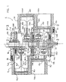
- Fig. 1 is a vertical sectional view of a horizontal opposed type internal combustion engine comprising a crank shaft supporting structure according to the invention
- Fig. 2 is a sectional view taken along line 2-2 of Fig. 1
- Fig. 3 is a sectional view taken along line 3-3 of Fig. 1
- Fig. 4 is a sectional view taken along line 4-4 of Fig. 1.
- symbol E denotes a horizontal opposed type 4-cylinder internal combustion engine, for automobile to which the invention has been applied.
- the internal combustion engine E comprises a crank shaft 1 disposed in the front-rear direction of the vehicle.
- Four cranks of the crank shaft 1 will be called No. 1 crank 2 1 , No. 2 crank 2 2 , No. 3 crank 2 3 , and No. 4 crank 2 4 , in this order from the front side of the vehicle.
- the No. 1 crank 2 1 and the No. 4 crank 2 4 as well as the No. 2 crank 2 2 and the No. 3 crank 2 3 are in the same phase with each other, and there is a phase difference of 180° between the first and fourth cranks 2 1 , 2 4 and the second and third cranks 2 2 and 2 3 .
- a front journal 3f is adjacently provided on the front side of the No. 1 crank 2 1
- a middle journal 3m is provided at a middle portion between the No. 2 and No. 3 cranks 2 2 , 2 3
- a rear journal 3r is adjacently provided on the rear side of the No. 4 crank 2 4 .
- cranks 2 1 , 2 3 are respectively connected with a front-rear pair of first pistons 4Lf, 4Lr through connecting rods 5Lf, 5Lr, whereas the No. 2 and No. 4 cranks 2 2 , 2 4 are respectively connected with a front-rear pair of second pistons 4Rf, 4Rr through connecting rods 5Rf, 5Rr.
- the first pistons 4Lf, 4Lr and the second pistons 4Rf, 4Rr are disposed oppositely on the left and right sides with the axis line A of the crank shaft 1 therebetween.
- the first piston 4Lf and the second piston 4Rf are set off from each other along the crank axis line A by the axial distance S between the corresponding No. 1 crank 2 1 and No. 2 crank 2 2 .
- a crankcase 6 for containing the crank shaft 1 is split along a vertical plane P containing the crank axis line A into a first case half 6L on the side of the first pistons 4Lf, 4Lr and a second case half 6R on the side of the second pistons 4Rf, 4Rr.
- the first and second case halves 6L, 6R are connected with first and second cylinder blocks 7L, 7R by pluralities of bolts 8L, 8L ... and 8R, 8R ... at the circumference of each cylinder block.
- cylinder sleeves 9Lf, 9Lr having cylinder bores 10Lf, 10Lr for slidable fitting therein of the first pistons 4Lf, 4Lr.
- second cylinder block 7R integrally joined, by insert-casting, cylinder sleeves 9Rf, 9Rr having cylinder bores 10Rf, 10Rr for slidable fitting therein of the second pistons 4Rf, 4Rr.
- the cylinder sleeves 9Lf, 9Lr, 9Rf, 9Rr are protruding from the inner ends of the first and second cylinder blocks 7L, 7R, and the protruding portions are received in sleeve receiving holes 11L, 11R provided in the first and second case halves 6L, 6R.
- the cylinder bores 10Lf, 10Rf of the first and second cylinder blocks 7L, 7R are also set off from each other by the above-mentioned distance S along the crank axis line A.
- the first case half 6L is provided integrally with three first journal supporting walls 13Lf, 13Lm, 13Lr for supporting half periphery portions of the front journal 3f, middle journal 3m and rear journal 3r through split bushes 12, respectively.
- the second case half 6R also, is provided integrally with three second journal supporting walls 13Rf, 13Rm, 13Rr for supporting the other half periphery portions of the front journal 3f, middle journal 3m and rear journal 3r through split bushes 12, respectively.
- the first and second journal supporting walls 13Lf, 13Rf at a front portion are located at a middle position along the crank axis line A between front walls 7Lf, 7Rf of the first and second cylinder blocks 7L, 7R.
- the first and second journal supporting walls 13Lm, 13Rm at an intermediate portion are located at a middle position along the crank axis line A between middle walls 7Lm, 7Rm of the first and second cylinder blocks 7L, 7R.
- the first and second journal supporting walls 13Lr, 13Rr at a rear portion are located at a middle position along the crank axis line A between rear walls 7Lr, 7Rr of the first and second cylinder blocks 7L, 7R.
- first journal supporting walls 13Lf, 13Lm at the front and intermediate portions are exposed to the side of the cylinder bores 10Lf, 10Lr of the first cylinder block 7L, and first journal supporting wall 13Lr at the rear portion is located on the rear side of the rear wall 7Lr of the first cylinder block 7L.
- portions of the second journal supporting walls 13Rm, 13Rr at the intermediate and rear portions are exposed to the side of the cylinder bores 10Rf, 10Rr of the second cylinder block 7R, and the journal supporting wall 13Rf at the front portion is located on the front side of the front wall 7Rf of the second cylinder block 7R.
- the first journal supporting wall 13Lr at the rear portion is provided with a pair of bolt holes 14L, 14L disposed in proximity to and on opposite sides of the rear journal 3r of the crank shaft 1, and the second journal supporting wall 13Rr at the rear portions is provided with a pair of screw holes 15R, 15R coinciding with the bolt holes 14L, 14L.
- the second journal supporting wall 13Rf at the front portion is provided with a pair of bolt holes 14R, 14R disposed in proximity to and on opposite sides of the front journal 3f of the crank shaft 1, and the first journal supporting wall 13Lf at the front portion is provided with a pair of screw holes 15L, 15L coinciding with the bolt holes 14R, 14R.
- the first journal supporting wall 13Lm at the middle portion is provided with a pair of bolt holes 16L, 16L opening into the rear cylinder bore 10Lr of the first cylinder block 7L and disposed in proximity to and on opposite sides of the middle journal 3m of the crank shaft 1, and the second journal supporting wall 13Rm at the middle portion is provided with a pair of screw holes 17R, 17R coinciding with the bolt holes 16L, 16L.
- the second journal supporting wall 13Rm at the middle portion is provided with a pair of bolt holes 16R, 16R opening into the front cylinder bore 10Rf of the second cylinder block 7R and disposed in proximity to and on opposite sides of the middle journal 3m
- the first journal supporting wall 13Lm at the middle portion is provided with a pair of screw holes 17L, 17L coinciding with the bolt holes 16R, 16R.
- the first and second journal supporting walls 13Lm, 13Rm at the intermediate portion are provided with pairs of bolt holes 16L, 16L and 16R, 16R and screw holes 17L, 17L and 17R, 17R.
- these bolt holes 16L, 16L and 16R, 16R and the screw holes 17L, 17L and 17R, 17R adjacent to each other would not interfere with each other, these bolt holes and screw holes are formed to be smaller in diameter than the bolt holes 14L, 14L and 14R, 14R and the screw holes 15L, 15L and 15R, 15R provided in the first and second journal supporting holes 13Lf, 13Lr and 13Rf, 13Rr at the front and rear portions.
- Bolts 18L, 18L; 18R, 18R; 19L, 19L; 19R, 19R passed through the bolt holes 14L, 14L; 14R, 14R; 16L, 16L; 16R, 16R are fitted into the corresponding screw holes 15L, 15L; 15R, 15R; 17L, 17L; 17R, 17R, whereby the opposed first and second journal supporting walls 13Lf, 13Lm, 13Lr and 13Rf, 13Rm, 13Rr are connected to each other.
- the first and second case halves 6L, 6R are connected to each other by a plurality of bolts 20, 20 ... at their peripheral portions.
- the connecting rods 5Lf, 5Rf, 5Lr, 5Rr are only connected to the No. 1 to No. 4 cranks 2 1 to 2 4 of the crank shaft 1, and the first and second case halves 6L, 6R are connected in the manner of sandwiching the crank shaft 1 therebetween.
- the bolts 18L, 18L; 18R, 18R; 19L, 19L; 19R, 19R passed through the bolt holes 14L, 14L; 14R, 14R; 16L, 16L; 16R, 16R are fitted into the screw holes 15L, 15L; 15R, 15R; 17L, 17L; 17R, 17R, whereby the opposed first and second journal supporting walls 13Lf, 13Lm, 13Lr and 13Rf, 13Rm, 13Rr are coupled to each other.
- journal supporting walls 13Lm, 13Rm can be provided with sufficient binding force because the journal supporting walls 13Lm, 13Rm are coupled by a total of four bolts 19L, 19L and 19R, 19R which are inserted from the side of the left and right sleeve receiving holes 11L, 11R.
- first and second journal supporting walls 13Lm, 13Rm at the middle portion are also bolt-connected in proximity to and on both sides of the crank shaft 1, in the same manner as the first and second journal, supporting walls 13Lf, 13Rf and 13Lr, 13Rr at the front and rear portions. Therefore, rigidity of support for the middle journal 3m of the crank shaft 1 can be enhanced effectively. As a result, the crankcase 6 can be made small in thickness, leading to a reduction in weight. In addition, since there is no need for any bearing cap for exclusive use for supporting the middle journal 3m, it is possible to contrive a reduction in the number of component parts and a simplification in structure.
- the pistons 4Lf, 4Rf, 4Lr, 4Rr are connected to the connecting rods 5Lf, 5Rf, 5Lr, 5Rr
- the first cylinder block 7L is connected to the first case half 6L by the bolts 8L, 8L ... while fitting the first pistons 4Lf, 4Lr in the cylinder bores 10Lf, 10Lr of the first cylinder block 7L.
- the second cylinder block 7R is connected to the second case half 6R by the bolts 8R, 8R ... while fitting the second pistons 4Rf, 4Rr in the cylinder bores 10Rf, 10Rr of the second cylinder block 7R.
- the present invention is not restricted to or by the above-mentioned embodiments, and various modifications in design can be made without stepping out of the gist of the invention.
- the first cylinder block 7L can be formed integrally with the first case half 6L
- the second cylinder block 7R can be formed integrally with the second case half 6R.
- connection of the pistons 4Lf, 4Lr and 4Rf, 4Rr with the connecting rods 5Lf, 5Lr and 5Rf, 5Rr is carried out in spite of the presence of the cylinder blocks 7L, 7R.
- the horizontal opposed type internal combustion engine according to the present invention can be applied also to internal combustion engines having six or more cylinders. Furthermore, by disposing a crank shaft along a center line of a vehicle, the horizontal opposed type internal combustion engine according to the invention can be used not only for automobiles but also for motorcycles and airplanes.
- a horizontal opposed type internal combustion engine comprising a crank shaft, pluralities of first and second pistons connected to the crank shaft, disposed opposite to each other with the crank shaft therebetween and arranged with an offset from each other along the axial direction of the crank shaft, a crankcase for containing and supporting the crank shaft, and first and second cylinder blocks connected to and disposed on both sides of the crankcase and having cylinder bores for slidable fitting therein of the first and second pistons, the crankcase being split along a plane containing the axis line of the crank shaft into first and second case halves connected respectively with the first and second cylinder blocks, the first and second case halves are provided integrally with first and second journal supporting walls rotatably supporting a middle journal of the crank shaft therebetween, the first and second journal supporting walls fronting on the cylinder bores of the first and second cylinder blocks, and the first and second journal supporting walls are connected by a plurality of first bolts inserted from the side of the cylinder
- first and second journal supporting walls for supporting the middle journal of the crank shaft therebetween can be bolt-connected easily without being interfered in any way by the presence of the first and second cylinder blocks.
- Both the journal supporting walls are bolt-connected on both sides of and in proximity to the middle journal of the crank shaft, whereby rigidity of support for the middle journal of the crank shaft can be enhanced effectively. Therefore, the crankcase can be made small in thickness, leading to a reduction in weight.' Besides, there is no need for any bearing cap for exclusive use for supporting the crank shaft, which enables a reduction in the number of component parts and a simplification in structure.
- the first and second journal supporting walls are connected by a plurality of second bolts inserted from the side of the cylinder bore of the second cylinder block and arranged on both sides of and in proximity to.the middle journal. Therefore, even though the amount of exposure of the first and second supporting walls into the cylinder bores of the first and second cylinder blocks is small and the bolts used are small in diameter, the journal supporting walls can be connected using at least four bolts inserted from the sides of the first and second cylinder blocks, whereby the journal supporting walls can be provided with sufficient binding force.
- Object In a horizontal opposed type internal combustion engine, to enable rigid support of a middle journal of a crank shaft through rational utilization of first and second case halves constituting a crankcase, and to thereby contribute to a simplification in structure and a reduction in weight.
- Solving Means In a horizontal opposed type internal combustion engine in which a crankcase 6 is split at a plane P containing the axis line A of a crank shaft 1 into first and second case halves 6L, 6R connected with first and second cylinder blocks.
- first and second case halves 6L, 6R are provided integrally with first and second journal supporting walls 13Lm, 13Rm for supporting a middle journal 3m of the crank shaft 1, the first and second journal supporting walls 13Lm, 13Rm fronting on cylinder bores 10Lr, 10Rf of the first and second cylinder blocks 7L, 7R, and the first and second journal supporting walls are coupled by a plurality of first bolts 19L inserted from the side of the cylinder bore 10Lr of the first cylinder block 7L and disposed on both sides of and in proximity to the middle journal 3m.
Landscapes
- Engineering & Computer Science (AREA)
- Chemical & Material Sciences (AREA)
- Combustion & Propulsion (AREA)
- Mechanical Engineering (AREA)
- General Engineering & Computer Science (AREA)
- Cylinder Crankcases Of Internal Combustion Engines (AREA)
- Shafts, Cranks, Connecting Bars, And Related Bearings (AREA)
Applications Claiming Priority (2)
| Application Number | Priority Date | Filing Date | Title |
|---|---|---|---|
| JP2000347645 | 2000-11-15 | ||
| JP2000347645 | 2000-11-15 |
Publications (3)
| Publication Number | Publication Date |
|---|---|
| EP1207292A2 true EP1207292A2 (de) | 2002-05-22 |
| EP1207292A3 EP1207292A3 (de) | 2003-04-23 |
| EP1207292B1 EP1207292B1 (de) | 2006-11-29 |
Family
ID=18821339
Family Applications (1)
| Application Number | Title | Priority Date | Filing Date |
|---|---|---|---|
| EP01121362A Expired - Lifetime EP1207292B1 (de) | 2000-11-15 | 2001-09-06 | Kurbelwellenunterstützung für eine Boxer-Brennkraftmaschine |
Country Status (4)
| Country | Link |
|---|---|
| EP (1) | EP1207292B1 (de) |
| AT (1) | ATE347028T1 (de) |
| CA (1) | CA2360402C (de) |
| DE (1) | DE60124847T2 (de) |
Cited By (2)
| Publication number | Priority date | Publication date | Assignee | Title |
|---|---|---|---|---|
| AT510872A1 (de) * | 2010-12-23 | 2012-07-15 | Avl List Gmbh | Brennkraftmaschine, insbesondere für rennfahrzeuge |
| FR3011879A1 (fr) * | 2013-10-14 | 2015-04-17 | Motorisations Aeronautiques | Moteur en configuration a plat avec agencement ameliore des bancs de cylindres |
Citations (1)
| Publication number | Priority date | Publication date | Assignee | Title |
|---|---|---|---|---|
| JP2000110582A (ja) | 1998-10-01 | 2000-04-18 | Honda Motor Co Ltd | 多気筒エンジン |
Family Cites Families (3)
| Publication number | Priority date | Publication date | Assignee | Title |
|---|---|---|---|---|
| FR1418021A (fr) * | 1964-01-08 | 1965-11-19 | Procedes Chabay | Carter précontraint |
| JP3133040B2 (ja) * | 1989-01-20 | 2001-02-05 | 富士重工業株式会社 | 水平対向型エンジンのクランクケース |
| DE4405188C2 (de) * | 1994-02-18 | 1997-10-02 | Porsche Ag | Brennkraftmaschine |
-
2001
- 2001-09-06 AT AT01121362T patent/ATE347028T1/de not_active IP Right Cessation
- 2001-09-06 DE DE60124847T patent/DE60124847T2/de not_active Expired - Lifetime
- 2001-09-06 EP EP01121362A patent/EP1207292B1/de not_active Expired - Lifetime
- 2001-10-29 CA CA002360402A patent/CA2360402C/en not_active Expired - Fee Related
Patent Citations (1)
| Publication number | Priority date | Publication date | Assignee | Title |
|---|---|---|---|---|
| JP2000110582A (ja) | 1998-10-01 | 2000-04-18 | Honda Motor Co Ltd | 多気筒エンジン |
Cited By (3)
| Publication number | Priority date | Publication date | Assignee | Title |
|---|---|---|---|---|
| AT510872A1 (de) * | 2010-12-23 | 2012-07-15 | Avl List Gmbh | Brennkraftmaschine, insbesondere für rennfahrzeuge |
| AT510872B1 (de) * | 2010-12-23 | 2012-09-15 | Avl List Gmbh | Brennkraftmaschine, insbesondere für rennfahrzeuge |
| FR3011879A1 (fr) * | 2013-10-14 | 2015-04-17 | Motorisations Aeronautiques | Moteur en configuration a plat avec agencement ameliore des bancs de cylindres |
Also Published As
| Publication number | Publication date |
|---|---|
| DE60124847T2 (de) | 2007-03-15 |
| DE60124847D1 (de) | 2007-01-11 |
| CA2360402C (en) | 2006-08-22 |
| ATE347028T1 (de) | 2006-12-15 |
| EP1207292B1 (de) | 2006-11-29 |
| EP1207292A3 (de) | 2003-04-23 |
| CA2360402A1 (en) | 2002-05-15 |
Similar Documents
| Publication | Publication Date | Title |
|---|---|---|
| US6334438B1 (en) | Overhead valve type internal combustion engine | |
| EP1207292B1 (de) | Kurbelwellenunterstützung für eine Boxer-Brennkraftmaschine | |
| US6158402A (en) | Engine block structure in multi-cylinder engine | |
| US6536399B2 (en) | Crankshaft supporting structure for horizontal opposed type internal combustion engine | |
| EP2110537B1 (de) | Motor und Fahrzeug | |
| JP2005076609A (ja) | 並列多気筒エンジン | |
| JP3074114U (ja) | オートバイ用駆動装置 | |
| JP4073737B2 (ja) | 多気筒エンジンのクランク室間連通構造 | |
| JP2002213302A (ja) | 水平対向型内燃機関におけるクランク軸支持構造 | |
| JPS6055687B2 (ja) | 多気筒v型エンジンを備えた自動二輪車 | |
| JP3619340B2 (ja) | 車両用v型内燃機関におけるシリンダブロック構造 | |
| JP3734218B2 (ja) | ベアリングキャップ構造 | |
| CN1143956C (zh) | 并列双气缸发动机 | |
| JP4210279B2 (ja) | ベアリングキャップ構造 | |
| JPS6349550Y2 (de) | ||
| JP2001347843A (ja) | エンジンの動力伝達装置 | |
| JP5352347B2 (ja) | 車両用エンジン | |
| JP4525237B2 (ja) | V型内燃機関 | |
| JP2730115B2 (ja) | 自動二輪車 | |
| JPH10176601A (ja) | 2ストローク内燃機関のクランクケース締付構造 | |
| JP2670109B2 (ja) | エンジン | |
| JP2560426B2 (ja) | 自動2輪車のエンジン | |
| JPS603386Y2 (ja) | 水平対向エンジンのクランク軸用軸受装置 | |
| JP3736951B2 (ja) | 多気筒エンジンのエンジンブロック構造 | |
| JP2006057605A (ja) | 4ストロークエンジン |
Legal Events
| Date | Code | Title | Description |
|---|---|---|---|
| PUAI | Public reference made under article 153(3) epc to a published international application that has entered the european phase |
Free format text: ORIGINAL CODE: 0009012 |
|
| AX | Request for extension of the european patent |
Free format text: AL;LT;LV;MK;RO;SI |
|
| PUAL | Search report despatched |
Free format text: ORIGINAL CODE: 0009013 |
|
| AK | Designated contracting states |
Designated state(s): AT BE CH CY DE DK ES FI FR GB GR IE IT LI LU MC NL PT SE TR |
|
| AX | Request for extension of the european patent |
Extension state: AL LT LV MK RO SI |
|
| 17P | Request for examination filed |
Effective date: 20030704 |
|
| AKX | Designation fees paid |
Designated state(s): AT DE FR |
|
| GRAP | Despatch of communication of intention to grant a patent |
Free format text: ORIGINAL CODE: EPIDOSNIGR1 |
|
| GRAS | Grant fee paid |
Free format text: ORIGINAL CODE: EPIDOSNIGR3 |
|
| GRAA | (expected) grant |
Free format text: ORIGINAL CODE: 0009210 |
|
| AK | Designated contracting states |
Kind code of ref document: B1 Designated state(s): AT DE FR |
|
| REF | Corresponds to: |
Ref document number: 60124847 Country of ref document: DE Date of ref document: 20070111 Kind code of ref document: P |
|
| ET | Fr: translation filed | ||
| PLBE | No opposition filed within time limit |
Free format text: ORIGINAL CODE: 0009261 |
|
| STAA | Information on the status of an ep patent application or granted ep patent |
Free format text: STATUS: NO OPPOSITION FILED WITHIN TIME LIMIT |
|
| 26N | No opposition filed |
Effective date: 20070830 |
|
| PGFP | Annual fee paid to national office [announced via postgrant information from national office to epo] |
Ref country code: AT Payment date: 20090911 Year of fee payment: 9 |
|
| PGFP | Annual fee paid to national office [announced via postgrant information from national office to epo] |
Ref country code: DE Payment date: 20090903 Year of fee payment: 9 |
|
| PGFP | Annual fee paid to national office [announced via postgrant information from national office to epo] |
Ref country code: FR Payment date: 20091012 Year of fee payment: 9 |
|
| REG | Reference to a national code |
Ref country code: FR Ref legal event code: ST Effective date: 20110531 |
|
| REG | Reference to a national code |
Ref country code: DE Ref legal event code: R119 Ref document number: 60124847 Country of ref document: DE Effective date: 20110401 |
|
| PG25 | Lapsed in a contracting state [announced via postgrant information from national office to epo] |
Ref country code: DE Free format text: LAPSE BECAUSE OF NON-PAYMENT OF DUE FEES Effective date: 20110401 Ref country code: FR Free format text: LAPSE BECAUSE OF NON-PAYMENT OF DUE FEES Effective date: 20100930 |
|
| PG25 | Lapsed in a contracting state [announced via postgrant information from national office to epo] |
Ref country code: AT Free format text: LAPSE BECAUSE OF NON-PAYMENT OF DUE FEES Effective date: 20100906 |