EP1207334B1 - Support - Google Patents
Support Download PDFInfo
- Publication number
- EP1207334B1 EP1207334B1 EP01125606A EP01125606A EP1207334B1 EP 1207334 B1 EP1207334 B1 EP 1207334B1 EP 01125606 A EP01125606 A EP 01125606A EP 01125606 A EP01125606 A EP 01125606A EP 1207334 B1 EP1207334 B1 EP 1207334B1
- Authority
- EP
- European Patent Office
- Prior art keywords
- arm
- cable
- stand
- support arm
- weight
- Prior art date
- Legal status (The legal status is an assumption and is not a legal conclusion. Google has not performed a legal analysis and makes no representation as to the accuracy of the status listed.)
- Expired - Lifetime
Links
- 230000005540 biological transmission Effects 0.000 claims description 12
- 230000008859 change Effects 0.000 claims description 8
- 230000009467 reduction Effects 0.000 claims description 5
- 238000012546 transfer Methods 0.000 claims description 4
- 238000010276 construction Methods 0.000 description 26
- 230000000694 effects Effects 0.000 description 8
- 238000013519 translation Methods 0.000 description 8
- 230000014616 translation Effects 0.000 description 8
- 230000005484 gravity Effects 0.000 description 5
- 239000003795 chemical substances by application Substances 0.000 description 3
- 230000008878 coupling Effects 0.000 description 3
- 238000010168 coupling process Methods 0.000 description 3
- 238000005859 coupling reaction Methods 0.000 description 3
- 238000013461 design Methods 0.000 description 3
- 238000011161 development Methods 0.000 description 3
- 230000018109 developmental process Effects 0.000 description 3
- 238000006073 displacement reaction Methods 0.000 description 3
- 230000006872 improvement Effects 0.000 description 3
- 230000033001 locomotion Effects 0.000 description 3
- NJPPVKZQTLUDBO-UHFFFAOYSA-N novaluron Chemical compound C1=C(Cl)C(OC(F)(F)C(OC(F)(F)F)F)=CC=C1NC(=O)NC(=O)C1=C(F)C=CC=C1F NJPPVKZQTLUDBO-UHFFFAOYSA-N 0.000 description 3
- 230000001447 compensatory effect Effects 0.000 description 2
- 230000007246 mechanism Effects 0.000 description 2
- 230000000903 blocking effect Effects 0.000 description 1
- 239000000969 carrier Substances 0.000 description 1
- 230000006835 compression Effects 0.000 description 1
- 238000007906 compression Methods 0.000 description 1
- 238000012937 correction Methods 0.000 description 1
- 238000001423 gas--liquid extraction Methods 0.000 description 1
- 238000004519 manufacturing process Methods 0.000 description 1
- 230000002265 prevention Effects 0.000 description 1
- 238000005096 rolling process Methods 0.000 description 1
- 238000012549 training Methods 0.000 description 1
- 238000004804 winding Methods 0.000 description 1
Images




Classifications
-
- F—MECHANICAL ENGINEERING; LIGHTING; HEATING; WEAPONS; BLASTING
- F16—ENGINEERING ELEMENTS AND UNITS; GENERAL MEASURES FOR PRODUCING AND MAINTAINING EFFECTIVE FUNCTIONING OF MACHINES OR INSTALLATIONS; THERMAL INSULATION IN GENERAL
- F16M—FRAMES, CASINGS OR BEDS OF ENGINES, MACHINES OR APPARATUS, NOT SPECIFIC TO ENGINES, MACHINES OR APPARATUS PROVIDED FOR ELSEWHERE; STANDS; SUPPORTS
- F16M11/00—Stands or trestles as supports for apparatus or articles placed thereon ; Stands for scientific apparatus such as gravitational force meters
- F16M11/42—Stands or trestles as supports for apparatus or articles placed thereon ; Stands for scientific apparatus such as gravitational force meters with arrangement for propelling the support stands on wheels
-
- A—HUMAN NECESSITIES
- A61—MEDICAL OR VETERINARY SCIENCE; HYGIENE
- A61B—DIAGNOSIS; SURGERY; IDENTIFICATION
- A61B90/00—Instruments, implements or accessories specially adapted for surgery or diagnosis and not covered by any of the groups A61B1/00 - A61B50/00, e.g. for luxation treatment or for protecting wound edges
- A61B90/20—Surgical microscopes characterised by non-optical aspects
- A61B90/25—Supports therefor
-
- F—MECHANICAL ENGINEERING; LIGHTING; HEATING; WEAPONS; BLASTING
- F16—ENGINEERING ELEMENTS AND UNITS; GENERAL MEASURES FOR PRODUCING AND MAINTAINING EFFECTIVE FUNCTIONING OF MACHINES OR INSTALLATIONS; THERMAL INSULATION IN GENERAL
- F16M—FRAMES, CASINGS OR BEDS OF ENGINES, MACHINES OR APPARATUS, NOT SPECIFIC TO ENGINES, MACHINES OR APPARATUS PROVIDED FOR ELSEWHERE; STANDS; SUPPORTS
- F16M11/00—Stands or trestles as supports for apparatus or articles placed thereon ; Stands for scientific apparatus such as gravitational force meters
- F16M11/02—Heads
- F16M11/04—Means for attachment of apparatus; Means allowing adjustment of the apparatus relatively to the stand
- F16M11/06—Means for attachment of apparatus; Means allowing adjustment of the apparatus relatively to the stand allowing pivoting
- F16M11/08—Means for attachment of apparatus; Means allowing adjustment of the apparatus relatively to the stand allowing pivoting around a vertical axis, e.g. panoramic heads
-
- F—MECHANICAL ENGINEERING; LIGHTING; HEATING; WEAPONS; BLASTING
- F16—ENGINEERING ELEMENTS AND UNITS; GENERAL MEASURES FOR PRODUCING AND MAINTAINING EFFECTIVE FUNCTIONING OF MACHINES OR INSTALLATIONS; THERMAL INSULATION IN GENERAL
- F16M—FRAMES, CASINGS OR BEDS OF ENGINES, MACHINES OR APPARATUS, NOT SPECIFIC TO ENGINES, MACHINES OR APPARATUS PROVIDED FOR ELSEWHERE; STANDS; SUPPORTS
- F16M11/00—Stands or trestles as supports for apparatus or articles placed thereon ; Stands for scientific apparatus such as gravitational force meters
- F16M11/20—Undercarriages with or without wheels
- F16M11/2007—Undercarriages with or without wheels comprising means allowing pivoting adjustment
- F16M11/2035—Undercarriages with or without wheels comprising means allowing pivoting adjustment in more than one direction
- F16M11/2064—Undercarriages with or without wheels comprising means allowing pivoting adjustment in more than one direction for tilting and panning
-
- F—MECHANICAL ENGINEERING; LIGHTING; HEATING; WEAPONS; BLASTING
- F16—ENGINEERING ELEMENTS AND UNITS; GENERAL MEASURES FOR PRODUCING AND MAINTAINING EFFECTIVE FUNCTIONING OF MACHINES OR INSTALLATIONS; THERMAL INSULATION IN GENERAL
- F16M—FRAMES, CASINGS OR BEDS OF ENGINES, MACHINES OR APPARATUS, NOT SPECIFIC TO ENGINES, MACHINES OR APPARATUS PROVIDED FOR ELSEWHERE; STANDS; SUPPORTS
- F16M11/00—Stands or trestles as supports for apparatus or articles placed thereon ; Stands for scientific apparatus such as gravitational force meters
- F16M11/20—Undercarriages with or without wheels
- F16M11/24—Undercarriages with or without wheels changeable in height or length of legs, also for transport only, e.g. by means of tubes screwed into each other
- F16M11/26—Undercarriages with or without wheels changeable in height or length of legs, also for transport only, e.g. by means of tubes screwed into each other by telescoping, with or without folding
- F16M11/28—Undercarriages for supports with one single telescoping pillar
-
- G—PHYSICS
- G02—OPTICS
- G02B—OPTICAL ELEMENTS, SYSTEMS OR APPARATUS
- G02B7/00—Mountings, adjusting means, or light-tight connections, for optical elements
- G02B7/001—Counterbalanced structures, e.g. surgical microscopes
-
- A—HUMAN NECESSITIES
- A61—MEDICAL OR VETERINARY SCIENCE; HYGIENE
- A61B—DIAGNOSIS; SURGERY; IDENTIFICATION
- A61B90/00—Instruments, implements or accessories specially adapted for surgery or diagnosis and not covered by any of the groups A61B1/00 - A61B50/00, e.g. for luxation treatment or for protecting wound edges
- A61B90/20—Surgical microscopes characterised by non-optical aspects
-
- F—MECHANICAL ENGINEERING; LIGHTING; HEATING; WEAPONS; BLASTING
- F16—ENGINEERING ELEMENTS AND UNITS; GENERAL MEASURES FOR PRODUCING AND MAINTAINING EFFECTIVE FUNCTIONING OF MACHINES OR INSTALLATIONS; THERMAL INSULATION IN GENERAL
- F16M—FRAMES, CASINGS OR BEDS OF ENGINES, MACHINES OR APPARATUS, NOT SPECIFIC TO ENGINES, MACHINES OR APPARATUS PROVIDED FOR ELSEWHERE; STANDS; SUPPORTS
- F16M2200/00—Details of stands or supports
- F16M2200/04—Balancing means
- F16M2200/044—Balancing means for balancing rotational movement of the undercarriage
-
- F—MECHANICAL ENGINEERING; LIGHTING; HEATING; WEAPONS; BLASTING
- F16—ENGINEERING ELEMENTS AND UNITS; GENERAL MEASURES FOR PRODUCING AND MAINTAINING EFFECTIVE FUNCTIONING OF MACHINES OR INSTALLATIONS; THERMAL INSULATION IN GENERAL
- F16M—FRAMES, CASINGS OR BEDS OF ENGINES, MACHINES OR APPARATUS, NOT SPECIFIC TO ENGINES, MACHINES OR APPARATUS PROVIDED FOR ELSEWHERE; STANDS; SUPPORTS
- F16M2200/00—Details of stands or supports
- F16M2200/06—Arms
- F16M2200/068—Arms being part of the undercarriage
Definitions
- the invention relates to a tripod, in particular for surgical microscopes.
- Surgical microscopes must be able to pivot slightly over a given range and should retain the posture set thereafter.
- balancing weights are provided in a group of known tripods which compensate for the weight of the microscope and its ancillary equipment. Most often, the balance weights are arranged balancing scale.
- Special training forms such Balkenwaagenan kannen example, the structure "OHS TM" by the applicant, in the parallelogram carrier balancing weights are laid from top to bottom, so that the overall center of gravity of the tripod is in the lower part of the tripod structure.
- the basic structure of the OHS TM is shown symbolically in the international patent application WO 97/13997 (1997) and the corresponding US Pat. No. 6,129,319.
- the weight compensation for the ease of use of a microscope or mobility of the same in the room and for the corresponding compensation of weight changes to the microscope by adding or removing additional equipment on the microscope is done in a known tripod "MS 1" the applicant via a compression spring diagonal a parallelogram supported.
- This parallelogram support is used in the construction of MS 1 as a swiveling horizontal support for the microscope.
- the particular parallel beam construction has been published by the Applicant in European Patent Application EP 433426 A1 (WO 91/472). In the international patent application WO 99/1693 (1999), the structure of the MS 1 is represented symbolically.
- the MS 1 provides as a balance weight before a switch box, the like, both the electrical power supply for the microscope, as well as its lighting device, its controls or the like. and optionally an additional weight.
- the control box is rigidly mounted on the vertical support column of the tripod and takes over there only a weight balance around the vertical axis of the vertical support column in terms of improving the tilting moment of the tripod.
- DD 221571 A1 (1985) shows a tripod structure with a lever arm, which compensates by a spring which is connected via a cable to the lever arm, weight.
- a spring which is connected via a cable to the lever arm, weight.
- the surgical microscope At the distal end of the lever arm is the surgical microscope. The basic adjustment of this surgical microscope via a threaded spindle, with the housing-fixed end of the spring is further pulled away from the lever arm or closer to him. Weight changes on the microscope are compensated by the fact that the articulation point of the cable is adjusted relative to the lever arm via a spindle.
- US 5,253,832 describes a tripod with a stand and a support arm pivotally mounted thereto for a load.
- the arm is connected via a cable with a spring.
- the cable-spring construction no improvement in the tilting security is achieved.
- FR 2 605 757 describes a photographic reflector with a tripod.
- the tripod is equipped with a cable-spring construction for weight compensation. Again, the cable-spring combination does not contribute to improving the tip resistance.
- DE 19742050 A1 (1999) discloses a stand construction with a pivotable parallelogram carrier, which is weight-compensated via a cable pull and a weight compensating spring so that the additionally present balance weights, which act according to the above-mentioned balance principle, can be made particularly small.
- the cable is guided in a special form in order to minimize the weight compensation error caused by the finite deflection radius in a wide pivoting range of the pivoting arm.
- the counterbalancing error is not eliminated by this measure, so that at certain pivoting positions an adjustment of the counterweights is still required to achieve the desired balance.
- the US 6070839 (2000) discloses a further structure with a pivoting arm and a cable-spring construction, which allows a pure weight balance - in the sense of the above-mentioned diagonal parallel Suss in MS1 - but without also contribute compensation moments to improve the stability against tilting.
- weight changes the pivot point of the cable, similar to the structure in the mentioned DD 221571, moved over a spindle.
- the main carrier which immediately picks up the load is often not attached directly to the vertical pedestal of the pedestal but to an additional horizontal arm projecting from that pedestal ,
- the tilting safety is achieved in these structures primarily by a corresponding design of the tripod foot, which must be correspondingly large and heavy.
- the weight compensation is, as already stated above, effected by a spring diagonally in the parallelogram or other measures specified above.
- An improvement in the anti-tipping and a certain compensation for tipping prevention is - as indicated above - optionally by the special arrangement of a control box or the like. possible.
- a tripod for surgical microscope which has a stand column and a support arm pivotable thereon.
- a cable is attached at one end, which is connected at its other end with a spring.
- the spring is stretched over the cable more or less.
- the spring does not contribute to an improvement in the anti-tipper due to their low weight here.
- the invention has for its object to provide a novel tripod for surgical microscopes, which is resistant to tipping, having as little volume and has an optimal weight compensation.
- Weight compensation is, on the one hand, the compensation of the weight of the load to understand, on the other hand, but also the compensation of any changes in this weight.
- a constant balancing force e.g. a weight is used for weight balance, the weight either in the vicinity of the column, e.g. on the opposite side of the load, concentric with the column stand or preferably housed within the column stand.
- the overall center of gravity of the tripod is very deep and can be placed in the direction of the column stand or tripod foot, so that the tilting behavior is improved for this reason.
- the inventive cable and the at least one pulley it is also possible to attach the balance weight at almost any point, or to lead the cable via various trained support arms (horizontal arm) or Tragarmmaschine without significant space requirements and without significant additional weights on the cable.
- the known structure requires a change in weight on the load, a change in the balance weight by adding or taking away weights. If you do not do that, you have to fix the ring on the column to prevent drifting. An automatic Balancieraus protest is thus not possible in this known structure.
- ropes may be used, the construction of which is tolerant of torsional loads.
- Such ropes are in particular, for example, left-right braided ropes, or combinations of left and right braided ropes.
- a particular embodiment of the invention provides to hang the balance weight on a Pulley, so it comes to a power transmission and the weight of the balance weight can be particularly high, resulting in improved stability of the tripod due to the particularly low center of gravity.
- the balance weight can be dimensioned only half as large by the translation of the balance weight leads to an enlarged way, but to an increased resulting force for weight balance.
- any translation options on a roller transmission are possible in which the cable is broken and attacks at the point of interruption on the one hand to a larger diameter roll and on the other hand, the other end of the other part of the cable to a roll rigidly connected to this smaller role engages, so that there is an over- or reduction of the force of the balance weight.
- comparable lever mechanisms can also be used.
- Another embodiment of the invention provides a kind of balance beam as a support arm for the load, which has at its load-remote end a guide along which the point of attack of a cable (sliding block) is displaceable.
- the cable is connected at its other end with a balance weight, which is freely suspended in height in the area of the column stand.
- a preferred and simple construction provides a displaceably mounted on a balance arm roller, which acts on a non-displaceable bracket on which the cable attack.
- the balance weight along the column stand is sliding or rolling stored or smoothly.
- at least one of the spindle adjustments can be designed to be electromotively, electromagnetically, hydraulically and / or pneumatically drivable.
- the drive is equipped with a brake for blocking the arms and / or at least one of the spindle adjustments is computer-controlled.
- a device cabinet with additional weight compensation function can be arranged on the vertical column stand.
- a horizontal arm is provided which is pivotable on the column stand in a horizontal plane and which supports the support arm pivotally in a horizontal plane.
- At least one deflection roller by means of a Spindle is designed to be adjustable in its relative position to the optionally displaceable articulation point of the cable.
- the balance weight is made up of at least two partial weights.
- At least two parallel cables are provided in a cable, in which preferably the winding direction is formed in opposite directions.
- FIG. 2 shows a variant of the structure according to FIG. 1, in which the point of attack of the parallelogram carrier 2b has been transferred to the vertical column 21 of the stand.
- the tilting behavior is improved because the balancing weight AG is on the left side of the vertical axis 1.
- the parallelogram carrier 2b penetrates into the space, which in the construction according to FIG. This leads to disabilities of the user, eg when working on an operating table OT, as symbolically indicated.
- FIG. 2a shows the plan view of the working position of the microscope according to FIG. 1 or 2.
- the basic structure of a tripod according to the invention according to Figure 3 is different in that the balance weight is designed in the form of a vertically freely movable compensation load AGa, the point of application on the balance-shaped compensating arm 22a, which is an extension of the support arm 2c, is mounted.
- a sliding block 23, to which a cable 24 is attached, is displaceable by means of a spindle 25 along the balance arm. If the slide shoe 23 is pushed further to the left, the effect (moment) of the balance weight AGa increases and the load G can be increased.
- the cable 24 could theoretically form a direct connection between the shoe 23 and the balance weight AGa. In such a direct connection, however, arises when pivoting of the support arm 2c a cosine error in the effective balance weight by the inclination of the cable 24th
- improved embodiment of the cable acts on a guide roller 26 whose fulcrum is fixed rigidly to the tripod column 21. This causes the cable of the cable 24 does not leave in the region of the balance weight AGa and above its parallel position to the stator column 21. In its area above the deflection roller 26, however, the cable of the cable pull 24 follows the sliding block 23, so that there an inclination of the rope with respect to the upright column 21 is possible.
- 3a shows a variant of this guide roller 26, which also serves as a translation:
- the cable 24 is divided into two parts in this variant, wherein the upper Part 24a is connected on the one hand with a roller 26a and on the other hand is attached to the shoe 23.
- the shoe 23 slides on the balance arm 22, which is held by the stator column 21.
- a smaller pulley 26b is rigidly connected to the larger 26a.
- the lower cable 24 b is fixed, or wound up, on the other hand connected to the balance weight AGa.
- a displacement of the sliding shoe 23 along the balance arm 22 thus leads to a rotation of the deflection roller 26a and to a rotationally equal rotation of the deflection roller 26b about the axis of rotation 27th
- the balance weight AGa can be significantly greater than it would have to be if the cable 24a were directly connected to the cable 24b.
- the two rollers 26a and 26b are reversed, resulting in a translation in which asammlungres balancing weight achieved a greater balancing effect than in the previously described case.
- the balancing weight AGa is arranged in a symbolic ring around the upright column 21.
- the balance weight is disposed within the column stand 21 or only on the side of the column stand 21, which is the load G about the axis 1 opposite.
- FIG 4 shows a structure without compensating arm 22.
- an arm 3 which is rigidly connected to the support arm 2, assumes the balancing function.
- an arm 4a Parallel to it, an arm 4a is provided, which has a spindle 19a.
- a connecting arm 5a is provided, which can be adjusted in its vertical position by means of the spindle 19a.
- a cable 24c is connected, which is guided around a guide roller 26c and carries at its other end the balancing weight AGb.
- the roller 26c can also be made in two parts as needed in accordance with the illustration in Fig. 3a and have a sub or translation function.
- Figure 5 As a variant to the structure of Figure 4, the construction of Figure 5 is to be understood, in which on the one hand acting as a taring gear parallelogram 6a is provided, but on the other hand instead of a simple support 28 according to Figure 4 for the guide roller 26c, a spindle-controlled support 28b provided is, which makes it possible to change parallel to the displacement of the connecting arm 5a and the position of the guide roller 26c. Although this means more mechanical and component expenses, but improves the compensation behavior of the overall arrangement.
- the load balancing unit 18 is constructed in FIG. 6 from the cable pull 24c, the deflection roller 26c and the balance weight AGb.
- the spindle 19a In an adjustment of the spindle 19a, there is a vertical displacement of the connecting arm 5a on the cheek of a carriage 7, which is laterally displaceable relative to the base body 12.
- the constant balancing force FA is applied to the car and thus on the connecting arm 5a, which brings only by its distance from the base body 12, the corresponding translation for weight changes in the load G with it.
- G is the load, or the surgical microscope, which is held at the distal end of a pivotable parallelogram carrier 2.
- the upper arm of the Parallelogrammmons 2 is rigidly connected to an arm 3, which is connected to a further parallel arm 4 and a connecting arm 5 to another parallelogram 6a.
- This parallelogram 6a forms the tare gear, in which the
- Connecting arm 5a is height adjustable in its parallel position, whereby the geometry of the parallelogram 6a by means of spindle 19a is variable.
- a pivoting of the parallelogram support 2 upwards or downwards leads to a pivoting of the parallelogram 6a to the left or to the right.
- the dashed line h max indicates the outermost position of the connecting arm 5 a, at which the greatest lever arm transmission exists, ie at which G can assume the greatest load.
- the weight AGb is shown freely suspended. In practice, this will of course be housed in a cage, on a guide rod or in the upright column of the tripod, as indicated for example in Figures 7 and 8.
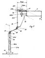
- FIG. 7 differs from FIGS. 3 to 6 in principle by an additional horizontal arm 29, which surrounds the support arm 2 by a vertical and pivotable about a horizontal axis.
- a support roller 30 is displaceable by means of a spindle along a balance arm 22b. It is irrelevant whether the roller 30 is seated on a nut, or whether it is mounted on a shoe which is longitudinally displaceable on a rod (extension of the upper arm of the support arm 2) by means of a parallel threaded spindle.
- a bracket 207 rests on the roller 30 and is guided on the one hand in a housing-fixed parallel guide 33 of the tare gear. On the other hand, it is connected to the cable of the cable 24d. If there is a longitudinal adjustment of the roller 30 through the spindle 31, this leads to a different counterbalancing weight attack on the cable 24d on the balance arm 22b. At the point 34, the cable 24 is torsionally coupled, so that the support arm 2 can pivot about a bearing 35 in a horizontal plane.
- balance weight AGb Inside the stator column 21 b is the balance weight AGb, which is preferably woodrekoppelt again via a rotary coupling 34.
- the balance weight AGb is preferably designed for transport reasons and for facilitated on-site assembly at least two parts.
- the relatively heavy balance weight AGb is distributed symmetrically about the vertical axis 1 of the column stand 21 b and advantageously causes a lowering of the overall center of gravity in the direction of the stand base 20.
- the balancing arm 22b corresponds approximately to the arm 3 from FIG.
- the spindle 31 performs approximately the same function as 19a of Fig.6.
- the bracket 207 has a similar function as the carriage 7 and its cheek 307 of Figure 6 and the roller 30 is approximately functionally identical to the roller 8 of Figure 6.
- the effective lengths h max -h min on the compensating arm 22b correspond to the lengths h max -h min on the arm 3 from FIG. Due to the guide 308a (Fig.6), or 308b (Fig.7), the cosine correction is ensured in both structures.
- rollers 36, 37 may be designed as a gear roller according to the construction according to FIG. 3 a in order to effect a transmission or reduction on the cable 24 d.
- Figure 9 shows a cable according to the invention constructed with a simple pulley.
- This includes a roller 55 which is movably positioned between the rollers 36 and 37.
- the cables 24a-c wrap around the roller 55 and are secured to the housing at 424. With this structure, this results in a translation of 2: 1. Within the scope of the invention are also other translations possible. The skilled person knows comparable hoists for hoists.
- roller 55 of the pulley 52 which has three parallel guide grooves 55a, 55b and 55c for receiving the three cables from the cable 24a, 24b and 24c therein.
- the roller 55 carries a roller yoke 85, which in turn is connected to the tethers 124a, 124b and 124c which provide the tensile force, e.g. to the bracket 207 (Fig.7) or to the shoe 23 (Fig.8) transmitted.
- FIG. 11 shows a stand structure constructed according to the invention with a microscope as a load G on a pivoting carrier 79, which is held by an integrated parallelogram carrier 2b.
- the carrier 2b is pivotally mounted on a bearing 119 of a horizontal arm 29, which is mounted on the stator column 21.
- a bow handle 88 serves as a transport aid and a device box 89 is used in addition to the inclusion of controls, power, lighting, etc. as additional Kippschreibsverêtung according to the structure MS. 1
Landscapes
- Engineering & Computer Science (AREA)
- General Engineering & Computer Science (AREA)
- Mechanical Engineering (AREA)
- Health & Medical Sciences (AREA)
- Surgery (AREA)
- Physics & Mathematics (AREA)
- Life Sciences & Earth Sciences (AREA)
- Optics & Photonics (AREA)
- Medical Informatics (AREA)
- Pathology (AREA)
- Nuclear Medicine, Radiotherapy & Molecular Imaging (AREA)
- General Physics & Mathematics (AREA)
- Biomedical Technology (AREA)
- Heart & Thoracic Surgery (AREA)
- Oral & Maxillofacial Surgery (AREA)
- Molecular Biology (AREA)
- Animal Behavior & Ethology (AREA)
- General Health & Medical Sciences (AREA)
- Public Health (AREA)
- Veterinary Medicine (AREA)
- Microscoopes, Condenser (AREA)
- Studio Devices (AREA)
Claims (10)
- Statif avec une colonne de support (21) et un bras porteur (2) pivotant dans un plan vertical, ayant pour charge (G) un microscope opératoire, et avec une force de compensation de poids (AG) assistée par câble pour l'équilibrage du bras porteur (2) dans des positions de pivotement libres, dans lequel la force de compensation équilibrante est appliquée au bras porteur (2) par l'intermédiaire d'un câble Bowden (24, 124) directement ou indirectement à une certaine distance de la colonne de support (21), avec un renvoi (26, 36, 37), par lequel le câble Bowden (24, 124) est renvoyé dans une direction parallèle à la colonne de support (21), caractérisé en ce que le câble Bowden (24, 124) est raccordé à un dispositif d'application d'une force de compensation constante (AGa ; AGb), et comme force de compensation (AGa ; AGb), un contrepoids (AG) est prévu qui est disposé de façon verticalement librement mobile à l'intérieur de la colonne de support (21) ou le long de celle-ci.
- Statif avec au moins un bras horizontal (29) sur une colonne de support (21) qui porte le bras porteur pivotant (2), selon la revendication 1, caractérisé en ce que le renvoi (26, 36, 37) amène le câble Bowden (24, 124) au moins à proximité ou à l'intérieur de la colonne de support (21).
- Statif selon la revendication 1 ou 2, caractérisé en ce que le point d'attaque proche du bras porteur pour le câble Bowden (24, 124) est fixé à un élément de transmission (5 ; 8) d'un engrenage de tarage (6) ou à un élément de transfert (7 ; 207) couplé à l'élément de transmission (5 ; 8).
- Statif avec un corps de base (12) sur lequel le bras porteur (2) est logé, selon la revendication 3, caractérisé en ce que l'élément de transfert est réalisé comme un chariot (7) ou un étrier (207) et fixé au corps de base (12) de façon mobile.
- Statif selon la revendication 4, caractérisé en ce qu'un élément de transmission (30) est réglable au moyen d'une broche (31) dans sa position relative par rapport à l'étrier (207).
- Statif selon l'une quelconque des revendications précédentes, caractérisé en ce que le contrepoids (AG) est suspendu à un palan (52).
- Statif selon les revendications 3 à 6, caractérisé en ce qu'au moins à un endroit du bras porteur (2), un ensemble de mesure pour déterminer la variation de charge est prévu, qui commande par l'intermédiaire d'au moins un entraînement électromoteur le réglage de l'engrenage de tarage (6a).
- Statif selon l'une quelconque des revendications précédentes, caractérisé en ce que le câble Bowden (24, 124) est interrompu au moins une fois et qu'à l'endroit d'interruption, un découplage rotatif est disposé, des câbles à tolérance de torsion étant utilisés pour le câble Bowden (24, 124) et le câble Bowden (24, 124) étant interrompu par un multiplicateur ou un démultiplicateur, le multiplicateur ou le démultiplicateur étant formé par au moins deux rouleaux de renvoi (26) qui sont reliés ensemble de façon verrouillée en rotation, les rouleaux (26a, 26b) présentant un diamètre différent.
- Statif selon l'une quelconque des revendications précédentes, caractérisé en ce que le câble Bowden (24) est fixé à un patin (23) qui est disposé de façon mobile sur un bras de compensation (22) raccordé rigidement au bras porteur (2) et le patin (23) est réglable au moyen d'une broche (25) dans sa position le long du bras de compensation (22).
- Statif selon la revendication 8, caractérisé en ce qu'entre l'engrenage de tarage (6) et le rouleau de renvoi (26), un chariot (7) est prévu, qui est logé de façon mobile face à une base commune (12) et sert à la transmission de force entre le câble Bowden (24) et l'engrenage de tarage (6).
Applications Claiming Priority (2)
| Application Number | Priority Date | Filing Date | Title |
|---|---|---|---|
| DE20019105U DE20019105U1 (de) | 2000-11-12 | 2000-11-12 | Stativ |
| DE20019105U | 2000-11-12 |
Publications (2)
| Publication Number | Publication Date |
|---|---|
| EP1207334A1 EP1207334A1 (fr) | 2002-05-22 |
| EP1207334B1 true EP1207334B1 (fr) | 2006-06-14 |
Family
ID=7948652
Family Applications (1)
| Application Number | Title | Priority Date | Filing Date |
|---|---|---|---|
| EP01125606A Expired - Lifetime EP1207334B1 (fr) | 2000-11-12 | 2001-10-26 | Support |
Country Status (4)
| Country | Link |
|---|---|
| US (1) | US7000873B2 (fr) |
| EP (1) | EP1207334B1 (fr) |
| JP (1) | JP4041669B2 (fr) |
| DE (2) | DE20019105U1 (fr) |
Families Citing this family (27)
| Publication number | Priority date | Publication date | Assignee | Title |
|---|---|---|---|---|
| DE50111444D1 (de) * | 2000-09-28 | 2006-12-28 | Leica Microsystems Schweiz Ag | Stativ |
| DE10142564A1 (de) | 2000-09-30 | 2002-04-11 | Zeiss Carl | Stativ |
| DE20019105U1 (de) * | 2000-11-12 | 2001-05-23 | Leica Microsystems Ag, Heerbrugg | Stativ |
| DE20019107U1 (de) | 2000-11-12 | 2001-01-25 | Leica Microsystems Ag, Heerbrugg | Stativ |
| DE20019106U1 (de) | 2000-11-12 | 2001-02-22 | Leica Microsystems Ag, Heerbrugg | Stativ mit Parallelogrammträger und Balanciermechanismus |
| DE20019109U1 (de) * | 2000-11-12 | 2001-02-22 | Leica Microsystems Ag, Heerbrugg | Stativ, insbesondere für Operationsmikroskope |
| DE10156318A1 (de) * | 2001-11-19 | 2003-05-28 | Zeiss Carl | Vorrichtung und Verfahren für wenigstens teilweisen Ausgleich eines Last-Drehmoments |
| US6539333B1 (en) | 2002-01-04 | 2003-03-25 | Leica Microsystems Ag | Stand having an automatic balancing device |
| FR2845889B1 (fr) * | 2002-10-22 | 2005-02-11 | Centre Nat Rech Scient | Robot chirurgical d'orientation et de positionnement d'un instrument chirurgical porteur d'un outil terminal chirurgical |
| US7837674B2 (en) * | 2005-01-24 | 2010-11-23 | Intuitive Surgical Operations, Inc. | Compact counter balance for robotic surgical systems |
| JP5350675B2 (ja) * | 2008-05-15 | 2013-11-27 | オリンパスメディカルシステムズ株式会社 | 医療用保持装置 |
| DE102008044028A1 (de) * | 2008-11-24 | 2010-08-12 | Cemecon Ag | Vorrichtung und Verfahren zum Beschichten eines Substrats mittels CVD |
| DE102011004926A1 (de) * | 2011-03-01 | 2012-09-06 | Karl Storz Gmbh & Co. Kg | Einstellbare Haltevorrichtung für ein Endoskop |
| US20120248273A1 (en) * | 2011-03-29 | 2012-10-04 | David Singer | Mounting system with adjustable height and load carrying surface |
| US8960632B2 (en) | 2011-07-05 | 2015-02-24 | Mediamounts, Ltd. | Dual bar linkage monitor support with adustment feature |
| DE102011056086A1 (de) * | 2011-12-06 | 2013-06-06 | Leica Microsystems (Schweiz) Ag | Stativ zum Halten von mindestens einem medizinischen Gerät, insbesondere einem Mikroskop |
| JP5433089B2 (ja) * | 2013-02-12 | 2014-03-05 | オリンパスメディカルシステムズ株式会社 | 医療用保持装置 |
| US9623270B2 (en) | 2014-06-25 | 2017-04-18 | Fall-Botics, Llc | Personal safety apparatus and system |
| CN113784682B (zh) | 2019-03-07 | 2024-09-20 | 普罗赛普特生物机器人公司 | 用于组织切除和成像的机器人臂和方法 |
| US10953536B2 (en) * | 2019-05-03 | 2021-03-23 | The Magstim Company Limited | Support arrangement for supporting a load in an elevated position |
| US11071601B2 (en) | 2019-11-11 | 2021-07-27 | Procept Biorobotics Corporation | Surgical probes for tissue resection with robotic arms |
| US12102851B2 (en) * | 2019-11-21 | 2024-10-01 | 3M Innovative Properties Company | Fall protection system |
| US11096753B1 (en) | 2020-06-26 | 2021-08-24 | Procept Biorobotics Corporation | Systems and methods for defining and modifying range of motion of probe used in patient treatment |
| US11877818B2 (en) | 2020-06-26 | 2024-01-23 | Procept Biorobotics Corporation | Integration of robotic arms with surgical probes |
| CN115605148A (zh) | 2021-04-20 | 2023-01-13 | 普罗赛普特生物机器人公司(Us) | 具有独立能量源的外科手术探针 |
| US12054364B2 (en) | 2021-10-21 | 2024-08-06 | Fall-Botics, Llc | Personal safety and fall protection systems |
| US20250223056A1 (en) | 2024-01-04 | 2025-07-10 | United Arab Emirates University | Low gravity simulator |
Family Cites Families (29)
| Publication number | Priority date | Publication date | Assignee | Title |
|---|---|---|---|---|
| DE221571C (fr) | ||||
| FR2181584B1 (fr) * | 1972-04-28 | 1977-07-22 | Luceat Sa | |
| FR2423424A1 (fr) * | 1978-04-20 | 1979-11-16 | Fmc Europe | Bras de chargement muni d'un dispositif de blocage hydraulique du tube externe. |
| DE7930125U1 (de) * | 1979-07-24 | 1980-01-24 | Contraves Ag, Zuerich (Schweiz) | Zusatzvorrichtung an einem stativ fuer ein optisches beobachtungsgeraet |
| GB2074337B (en) * | 1980-04-15 | 1983-11-16 | Univ Technology | Adjustable support for an optical or other instrument |
| JPS58117611U (ja) * | 1982-02-03 | 1983-08-11 | 東京光学機械株式会社 | 医療機器支持装置 |
| JPS58117613U (ja) * | 1982-02-03 | 1983-08-11 | 東京光学機械株式会社 | 医療機器支持装置 |
| DD221571B1 (de) * | 1984-02-01 | 1989-06-14 | Zeiss Jena Veb Carl | Drehgelenk mit einer einrichtung zur kompensation unterschiedlicher lastmomente |
| US4685648A (en) * | 1985-05-17 | 1987-08-11 | Bausch & Lomb Incorporated | Counterbalancing apparatus for use in an optical instrument |
| JP2510636Y2 (ja) * | 1986-05-15 | 1996-09-18 | オリンパス光学工業株式会社 | 手術用顕微鏡 |
| FR2605757B1 (fr) * | 1986-10-27 | 1989-05-19 | Binet Alain | Reflecteur photographique |
| US4738448A (en) * | 1987-02-09 | 1988-04-19 | Liester Arvin F | Support assembly for a basketball basket and backboard |
| DE3739080A1 (de) | 1987-11-01 | 1989-05-11 | Stemme Otto | Federvorrichtung zum gewichtausgleich fuer stative |
| DE3921857A1 (de) | 1989-07-04 | 1991-01-17 | Wild Leitz Ag | Mit zusatzvorrichtungen ausgestattetes stativ fuer die halterung eines frei positionierbaren geraetes |
| US5253832A (en) | 1991-07-26 | 1993-10-19 | Bolas Mark T | Spring counterbalanced boom suspension system |
| US5397323A (en) | 1992-10-30 | 1995-03-14 | International Business Machines Corporation | Remote center-of-motion robot for surgery |
| US5825536A (en) | 1994-09-12 | 1998-10-20 | Olympus Optical Co., Ltd. | Surgical microscope unit |
| DE29624639U1 (de) | 1995-10-12 | 2006-06-08 | Leica Microsystems (Schweiz) Ag | Stativ |
| US5746404A (en) * | 1996-02-15 | 1998-05-05 | Merko; Andrew V. | Apparatus for counterbalancing equipment |
| DE19711572B4 (de) | 1997-03-20 | 2006-09-07 | Carl Zeiss | Operationsmikroskopstativ |
| DE59812659D1 (de) | 1997-06-30 | 2005-04-21 | Leica Microsystems Schweiz Ag | Stativgewichtsausgleich |
| US6105909A (en) * | 1997-09-24 | 2000-08-22 | Carl-Zeiss-Stiftung | Stand with energy storage device for weight equalization |
| DE19742050B4 (de) | 1997-09-24 | 2008-07-31 | Carl Zeiss | Stativ mit Gewichtsausgleich |
| JPH11244301A (ja) * | 1998-02-27 | 1999-09-14 | Olympus Optical Co Ltd | 手術用顕微鏡 |
| US5984811A (en) * | 1998-06-03 | 1999-11-16 | Taylor; Bryce | Adjustable basketball standard |
| DE10142564A1 (de) * | 2000-09-30 | 2002-04-11 | Zeiss Carl | Stativ |
| DE20019107U1 (de) * | 2000-11-12 | 2001-01-25 | Leica Microsystems Ag, Heerbrugg | Stativ |
| DE20019106U1 (de) | 2000-11-12 | 2001-02-22 | Leica Microsystems Ag, Heerbrugg | Stativ mit Parallelogrammträger und Balanciermechanismus |
| DE20019105U1 (de) * | 2000-11-12 | 2001-05-23 | Leica Microsystems Ag, Heerbrugg | Stativ |
-
2000
- 2000-11-12 DE DE20019105U patent/DE20019105U1/de not_active Expired - Lifetime
-
2001
- 2001-10-26 DE DE50110135T patent/DE50110135D1/de not_active Expired - Lifetime
- 2001-10-26 EP EP01125606A patent/EP1207334B1/fr not_active Expired - Lifetime
- 2001-11-08 US US10/010,101 patent/US7000873B2/en not_active Expired - Fee Related
- 2001-11-12 JP JP2001346733A patent/JP4041669B2/ja not_active Expired - Fee Related
Also Published As
| Publication number | Publication date |
|---|---|
| DE20019105U1 (de) | 2001-05-23 |
| EP1207334A1 (fr) | 2002-05-22 |
| DE50110135D1 (de) | 2006-07-27 |
| US20020121577A1 (en) | 2002-09-05 |
| JP4041669B2 (ja) | 2008-01-30 |
| US7000873B2 (en) | 2006-02-21 |
| JP2002207174A (ja) | 2002-07-26 |
Similar Documents
| Publication | Publication Date | Title |
|---|---|---|
| EP1207334A1 (fr) | Support | |
| EP2962673B1 (fr) | Colonne de table d'opération pour table d'opération | |
| EP1538386B1 (fr) | Support | |
| DE10042272B4 (de) | Stativanordnung | |
| EP0433426B1 (fr) | Statif equipe de dispositifs accessoires, pour supporter un appareil librement orientable | |
| DE3119934A1 (de) | Flurfreie hubvorrichtung mit beweglicher arbeitsplattform und belastungsanzeige | |
| EP1324094B1 (fr) | Statif avec un microscope chirurgical | |
| EP1251380A2 (fr) | Statif pour un microscope d'opération | |
| EP0303637B1 (fr) | Dispositif de levage pour appareils de laboratoire ayant un statif et un plateau de base, et chauffe-bain de laboratoire, notamment pour vaporisateurs rotatifs | |
| EP1205703B1 (fr) | Support,en particulier pour microscope chirurgical | |
| DE19742051B4 (de) | Stativ mit Energiespeicher zum Gewichtsausgleich | |
| DE19742050B4 (de) | Stativ mit Gewichtsausgleich | |
| DE2438439A1 (de) | Kran | |
| EP0496994B1 (fr) | Support | |
| EP1484112B1 (fr) | Support ajustable en hauteur, et méthode de découplage du système de maintien associé à ce support | |
| CH692926A5 (de) | Stativ mit Energiespeicher zum Gewichtsausgleich. | |
| WO2008128556A1 (fr) | Dispositif d'arrêt pour équipement d'optique médicale, en particulier pour moniteur | |
| EP3861958A1 (fr) | Dispositif d'articulation de bras de support et système de support pour un dispositif médical | |
| DE2704528C2 (de) | Gegengewichtsausgleich für ein Röntgenuntersuchungsgerät | |
| DE10314156B9 (de) | Schwenkhalterungsanordnung und Verfahren zum Steuern einer solchen | |
| DE3020562A1 (de) | Vorrichtung zum manuellen bewegen von lasten | |
| DE4014003A1 (de) | Mechanischer momentenausgleich | |
| EP0376036B1 (fr) | Nacelle de sauvetage et/ou de travail | |
| DE19742048B4 (de) | Stativ mit einer Linearschlitten/Schwenkeinheit als Verstellvorrichtung | |
| EP0547377A2 (fr) | Support pour appareil à rayons X |
Legal Events
| Date | Code | Title | Description |
|---|---|---|---|
| PUAI | Public reference made under article 153(3) epc to a published international application that has entered the european phase |
Free format text: ORIGINAL CODE: 0009012 |
|
| AX | Request for extension of the european patent |
Free format text: AL;LT;LV;MK;RO;SI |
|
| 17P | Request for examination filed |
Effective date: 20021102 |
|
| AKX | Designation fees paid |
Designated state(s): DE FR GB |
|
| 17Q | First examination report despatched |
Effective date: 20041209 |
|
| GRAP | Despatch of communication of intention to grant a patent |
Free format text: ORIGINAL CODE: EPIDOSNIGR1 |
|
| GRAS | Grant fee paid |
Free format text: ORIGINAL CODE: EPIDOSNIGR3 |
|
| GRAA | (expected) grant |
Free format text: ORIGINAL CODE: 0009210 |
|
| AK | Designated contracting states |
Kind code of ref document: B1 Designated state(s): DE FR GB |
|
| REG | Reference to a national code |
Ref country code: GB Ref legal event code: FG4D Free format text: NOT ENGLISH |
|
| REF | Corresponds to: |
Ref document number: 50110135 Country of ref document: DE Date of ref document: 20060727 Kind code of ref document: P |
|
| GBT | Gb: translation of ep patent filed (gb section 77(6)(a)/1977) |
Effective date: 20060923 |
|
| ET | Fr: translation filed | ||
| PLBE | No opposition filed within time limit |
Free format text: ORIGINAL CODE: 0009261 |
|
| STAA | Information on the status of an ep patent application or granted ep patent |
Free format text: STATUS: NO OPPOSITION FILED WITHIN TIME LIMIT |
|
| 26N | No opposition filed |
Effective date: 20070315 |
|
| REG | Reference to a national code |
Ref country code: GB Ref legal event code: 732E Free format text: REGISTERED BETWEEN 20100304 AND 20100310 |
|
| REG | Reference to a national code |
Ref country code: FR Ref legal event code: CD |
|
| REG | Reference to a national code |
Ref country code: FR Ref legal event code: TP |
|
| REG | Reference to a national code |
Ref country code: FR Ref legal event code: PLFP Year of fee payment: 15 |
|
| PGFP | Annual fee paid to national office [announced via postgrant information from national office to epo] |
Ref country code: DE Payment date: 20151030 Year of fee payment: 15 |
|
| REG | Reference to a national code |
Ref country code: FR Ref legal event code: PLFP Year of fee payment: 16 |
|
| PGFP | Annual fee paid to national office [announced via postgrant information from national office to epo] |
Ref country code: FR Payment date: 20161027 Year of fee payment: 16 Ref country code: GB Payment date: 20161028 Year of fee payment: 16 |
|
| REG | Reference to a national code |
Ref country code: DE Ref legal event code: R119 Ref document number: 50110135 Country of ref document: DE |
|
| PG25 | Lapsed in a contracting state [announced via postgrant information from national office to epo] |
Ref country code: DE Free format text: LAPSE BECAUSE OF NON-PAYMENT OF DUE FEES Effective date: 20170503 |
|
| GBPC | Gb: european patent ceased through non-payment of renewal fee |
Effective date: 20171026 |
|
| REG | Reference to a national code |
Ref country code: FR Ref legal event code: ST Effective date: 20180629 |
|
| PG25 | Lapsed in a contracting state [announced via postgrant information from national office to epo] |
Ref country code: GB Free format text: LAPSE BECAUSE OF NON-PAYMENT OF DUE FEES Effective date: 20171026 |
|
| PG25 | Lapsed in a contracting state [announced via postgrant information from national office to epo] |
Ref country code: FR Free format text: LAPSE BECAUSE OF NON-PAYMENT OF DUE FEES Effective date: 20171031 |