EP1207421A1 - Verfahren und Vorrichtung zur Herstellung und Montage von radiografischen Bildern - Google Patents
Verfahren und Vorrichtung zur Herstellung und Montage von radiografischen Bildern Download PDFInfo
- Publication number
- EP1207421A1 EP1207421A1 EP01870245A EP01870245A EP1207421A1 EP 1207421 A1 EP1207421 A1 EP 1207421A1 EP 01870245 A EP01870245 A EP 01870245A EP 01870245 A EP01870245 A EP 01870245A EP 1207421 A1 EP1207421 A1 EP 1207421A1
- Authority
- EP
- European Patent Office
- Prior art keywords
- radio
- radiographic images
- acquisition
- segment
- images according
- Prior art date
- Legal status (The legal status is an assumption and is not a legal conclusion. Google has not performed a legal analysis and makes no representation as to the accuracy of the status listed.)
- Ceased
Links
- 238000000034 method Methods 0.000 title claims description 26
- 239000003550 marker Substances 0.000 claims abstract description 7
- 238000004846 x-ray emission Methods 0.000 claims description 2
- 238000002601 radiography Methods 0.000 abstract description 4
- 238000012937 correction Methods 0.000 description 10
- OAICVXFJPJFONN-UHFFFAOYSA-N Phosphorus Chemical compound [P] OAICVXFJPJFONN-UHFFFAOYSA-N 0.000 description 8
- 229920000297 Rayon Polymers 0.000 description 5
- 239000002964 rayon Substances 0.000 description 5
- 230000005855 radiation Effects 0.000 description 4
- 229910052698 phosphorus Inorganic materials 0.000 description 3
- 239000011574 phosphorus Substances 0.000 description 3
- 238000001914 filtration Methods 0.000 description 2
- 238000009434 installation Methods 0.000 description 2
- 210000003141 lower extremity Anatomy 0.000 description 2
- 238000012545 processing Methods 0.000 description 2
- 238000012800 visualization Methods 0.000 description 2
- 241001465754 Metazoa Species 0.000 description 1
- 241000135309 Processus Species 0.000 description 1
- 238000012217 deletion Methods 0.000 description 1
- 230000037430 deletion Effects 0.000 description 1
- 238000011161 development Methods 0.000 description 1
- 230000004927 fusion Effects 0.000 description 1
- 238000003702 image correction Methods 0.000 description 1
- 239000000463 material Substances 0.000 description 1
- 238000012986 modification Methods 0.000 description 1
- 230000004048 modification Effects 0.000 description 1
- 238000007781 pre-processing Methods 0.000 description 1
- 239000011347 resin Substances 0.000 description 1
- 229920005989 resin Polymers 0.000 description 1
Images





Classifications
-
- G—PHYSICS
- G03—PHOTOGRAPHY; CINEMATOGRAPHY; ANALOGOUS TECHNIQUES USING WAVES OTHER THAN OPTICAL WAVES; ELECTROGRAPHY; HOLOGRAPHY
- G03B—APPARATUS OR ARRANGEMENTS FOR TAKING PHOTOGRAPHS OR FOR PROJECTING OR VIEWING THEM; APPARATUS OR ARRANGEMENTS EMPLOYING ANALOGOUS TECHNIQUES USING WAVES OTHER THAN OPTICAL WAVES; ACCESSORIES THEREFOR
- G03B42/00—Obtaining records using waves other than optical waves; Visualisation of such records by using optical means
- G03B42/02—Obtaining records using waves other than optical waves; Visualisation of such records by using optical means using X-rays
- G03B42/04—Holders for X-ray films
- G03B42/047—Holders for X-ray films provided with marking means
Definitions
- the invention relates to a technique for radiography of the human or animal body, and in particular to a technique concerning obtaining radiographic images of members in their entirety and / or obtaining images x-rays of the entire spine.
- a radio-sensitive surface such as an X-ray film. or a photostimulable screen (commonly called a phosphor screen), generally contained in a radio-sensitive support such as a receptacle sealed against daylight (commonly called a "cassette") and subjected to X-rays after they have passed through a segment to explore.
- a radio-sensitive support such as a receptacle sealed against daylight (commonly called a "cassette"
- the usual dimensions of radio-sensitive surfaces are 36cm x 43cm, which is clearly insufficient.
- the photostimulable screens currently available on the market are limited to the maximum format of 36cm x 43cm. Exploring a segment 90 to 120 cm high therefore requires the use of several photostimul
- the method consists in acquiring two or more images of a segment of an object to be radiographed on two or more radio-sensitive surfaces positioned so as to overlap at least partially, defining thus an overlay area. We can then reconstruct a complete overview of the segment by stitching of two or more images by making overlap the corresponding image parts.
- a mark is also used radiopaque alignment joint placed in or at the right of the overlapping area, so as to obtain the image of this mark on each radio-sensitive surface.
- Said benchmark alignment joint is positioned in a central plane of X-rays perpendicular to the plane of a radio-sensitive surface so as to greatly reduce errors of parallax. The images of this common alignment mark will allow later to reconstruct the image complete overview of the segment with great precision by superimposition of said images of said reference mark.
- the edges of the radio-sensitive surfaces are not substantially parallel to one another during the acquisition of the images, use is made in some cases of several - preferably two - radio alignment marks. opaque in or to the right of the superposition zone, so as to obtain the image of these alignment marks on each radio-sensitive surface. This will later allow the overall image to be reconstructed, taking into account this lack of parallelism during the acquisition.
- the shape of the alignment marks is generally any, and preferably a circle or a cross reticular.
- the dimension of the alignment marks is as small as possible so as not to interfere with the reading of the image ray.
- Preferably at least one of the dimensions alignment marks is between one and five times the inverse of the graphic resolution of the images acquired. This will increase the precision of the assembly.
- the dimension of the overlapping area must be sufficient to allow precise identification of radiopaque alignment marks and as small as possible in order to obtain a total acquisition area as large as possible in a single irradiation of two or several or several radio-sensitive media successive irradiations of one or more supports radio-sensitive.
- Radio-sensitive surfaces can either be placed in the same plan, in which case the images are acquired successively - that is to say by means of several successive irradiations - either to be in plans parallel and adjacent, in which case the images are acquired either simultaneously - i.e. by means of a only irradiation - either successively - i.e. at by means of several successive irradiations.
- At least one radiopaque laterality mark between the ray source X and each of the radio-sensitive surfaces said reference mark laterality being positioned outside the central plane of the rays X in order to be able to determine the laterality of the images acquired radiographs.
- the difference in distance separating the radio-sensitive surfaces of an X-ray emission source is responsible for an enlargement factor of the segment the different radiographed object for the image formed on the radio-sensitive surface furthest from the emission focus and for the image formed on the radio-sensitive surface the closer to the source of emission. If the distance between the radio-sensitive surfaces of the emission focal point is short, the magnification difference will be important and will require correction of the images before mounting. If the distance between the radio-sensitive surfaces of the emission focus is large, the difference of magnification factor will be negligible and will not require no correction of images before editing.
- the distance separating the radio-sensitive surfaces of the emission focus is substantially identical for all radio-sensitive surfaces, and therefore there is no need to perform this correction.
- the invention also relates to a system and a device. for the acquisition of radiographic images of a segment object, a description of which can be found in claims and in the detailed description of modes of particular realization.
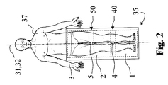
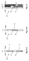
- a stand (35) in which the cassettes will be positioned so overlap in an overlapping area (40).
- X-ray orientation - and in particular the plane central x-ray (31) - do not vary during the acquisition.
- the position and the orientation of the X-ray source (36) and the segment do not vary upon acquisition.
- the assembly will be carried out by assembling the physical support of the radiographic image if it is a direct acquisition on radio-sensitive film or if it is a digital acquisition which one wishes to have a format determined for the presentation of the result.
- the editing will be carried out by digital fusion of the images acquired on a radio-sensitive receiver (Screen known as "with Phosphorus") and may be presented either on digital support, or printed on transparent or opaque support.
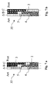
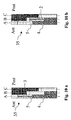
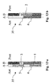
- the manipulation of digital images will be done with rigor: in order to avoid laterality errors we propose to use a laterality marking device (1.2.3.5) which can usefully be supplemented by a device for tracing the manipulation of images thanks to memorization of the history of all computer modifications of the image.
- mounting can be carried out directly by assembling two to two of the images by superimposing the common image of the alignment mark located in the area of overlay.
- Image correction will be performed manually or automatically by software taking into account the relative position of the different radio-sensitive receivers : after selecting in a row and a level determined an image taken for reference and for which no correction is made, the or other images are corrected, reduced or enlarged, according to the enlargement coefficient linked to the relative position of this image with respect to the image taken for reference.
Landscapes
- Physics & Mathematics (AREA)
- General Physics & Mathematics (AREA)
- Apparatus For Radiation Diagnosis (AREA)
Applications Claiming Priority (2)
| Application Number | Priority Date | Filing Date | Title |
|---|---|---|---|
| BE2000/0731A BE1013837A3 (fr) | 2000-11-16 | 2000-11-16 | Systeme d'acquisition d'images radiographiques et de montage panoramique. |
| BE200000731 | 2000-11-16 |
Publications (1)
| Publication Number | Publication Date |
|---|---|
| EP1207421A1 true EP1207421A1 (de) | 2002-05-22 |
Family
ID=3896759
Family Applications (1)
| Application Number | Title | Priority Date | Filing Date |
|---|---|---|---|
| EP01870245A Ceased EP1207421A1 (de) | 2000-11-16 | 2001-11-16 | Verfahren und Vorrichtung zur Herstellung und Montage von radiografischen Bildern |
Country Status (2)
| Country | Link |
|---|---|
| EP (1) | EP1207421A1 (de) |
| BE (1) | BE1013837A3 (de) |
Cited By (1)
| Publication number | Priority date | Publication date | Assignee | Title |
|---|---|---|---|---|
| WO2012147081A1 (en) | 2011-04-25 | 2012-11-01 | Generic Imaging Ltd. | System and method for correction of geometric distortion of multi-camera flat panel x-ray detectors |
Citations (2)
| Publication number | Priority date | Publication date | Assignee | Title |
|---|---|---|---|---|
| US3725703A (en) * | 1971-06-09 | 1973-04-03 | P Bucky | X-ray film cassette |
| US3774045A (en) * | 1972-09-28 | 1973-11-20 | R Trott | Cart top x-ray cassette holder |
Family Cites Families (3)
| Publication number | Priority date | Publication date | Assignee | Title |
|---|---|---|---|---|
| US1678038A (en) * | 1927-05-09 | 1928-07-24 | Philip K Eaton | Method of marking x-ray films |
| JPH02104174A (ja) * | 1988-10-13 | 1990-04-17 | Toshiba Corp | X線診断装置 |
| DE9113810U1 (de) * | 1991-11-06 | 1991-12-19 | Agfa-Gevaert Ag, 5090 Leverkusen | Röntgenblattfilmmagazin |
-
2000
- 2000-11-16 BE BE2000/0731A patent/BE1013837A3/fr not_active IP Right Cessation
-
2001
- 2001-11-16 EP EP01870245A patent/EP1207421A1/de not_active Ceased
Patent Citations (2)
| Publication number | Priority date | Publication date | Assignee | Title |
|---|---|---|---|---|
| US3725703A (en) * | 1971-06-09 | 1973-04-03 | P Bucky | X-ray film cassette |
| US3774045A (en) * | 1972-09-28 | 1973-11-20 | R Trott | Cart top x-ray cassette holder |
Cited By (3)
| Publication number | Priority date | Publication date | Assignee | Title |
|---|---|---|---|---|
| WO2012147081A1 (en) | 2011-04-25 | 2012-11-01 | Generic Imaging Ltd. | System and method for correction of geometric distortion of multi-camera flat panel x-ray detectors |
| EP2702449A4 (de) * | 2011-04-25 | 2014-11-26 | Generic Imaging Ltd | System und verfahren zur korrektur geometrischer verzerrungen von mehrkamera-flachbild-röntgendetektoren |
| US9291726B2 (en) | 2011-04-25 | 2016-03-22 | Generic Imaging Ltd. | System and method for correction of geometric distortion of multi-camera flat panel X-ray detectors |
Also Published As
| Publication number | Publication date |
|---|---|
| BE1013837A3 (fr) | 2002-09-03 |
Similar Documents
| Publication | Publication Date | Title |
|---|---|---|
| US20090202043A1 (en) | Polychromic Digital Radiography Detector with Patterned Mask for Single-Exposure Energy-Sensitive X-Ray Imaging | |
| US6459094B1 (en) | Method for stitching partial radiation images to reconstruct a full image | |
| FR3024235A1 (fr) | Systeme d'imagerie planaire permettant la correction du diffuse | |
| EP0785674A1 (de) | Apparat für Röntgenaufnahmen und Verfahren zur Bildverarbeitung | |
| JPS6388688A (ja) | 作像システムにおける図の間の動きを補正する装置及び方法 | |
| EP2059904A1 (de) | Computerisiertes abbildungsverfahren zur dreidimensionalen rekonstruktion zweidimensionaler radiologischer bilder und vorrichtung zu dessen anwendung | |
| EP0673623A1 (de) | Schichtabtastung für Röntgenaufnahme | |
| EP1511421B1 (de) | Stereoradiographie-vorrichtung und anwendungsverfahren dafür | |
| JP2001238136A (ja) | 検出器の欠陥ピクセル訂正 | |
| JP4574202B2 (ja) | 放射線撮影支持台 | |
| EP1615560B1 (de) | Phantom für die qualitätskontrolle eines systems zur virtuellen simulation einer radiotherapeutischen behandlung | |
| EP1207421A1 (de) | Verfahren und Vorrichtung zur Herstellung und Montage von radiografischen Bildern | |
| JP4427204B2 (ja) | 放射線画像情報生成装置の性能判定方法およびシステム | |
| EP0137465A3 (de) | Filmaufnahmen mit zwei Röntgenstrahlenergien | |
| US7203273B2 (en) | Scanning dual energy X-ray imaging | |
| JP2598636B2 (ja) | 画像処理条件決定方法 | |
| JP2824878B2 (ja) | 放射線画像のエネルギーサブトラクション撮影処理方法 | |
| JPS5910839A (ja) | サブトラクシヨン画像の処理方法 | |
| JPH0520026B2 (de) | ||
| JP2004229735A (ja) | 放射線像記録読取装置 | |
| JPH03133278A (ja) | エネルギーサブトラクション画像の形成方法および装置 | |
| JPH0614172B2 (ja) | X線画像のエネルギー・サブトラクシヨン方法およびその方法に用いられる積層体 | |
| JPH0670236A (ja) | 放射線画像の位置合せ方法 | |
| JPH0685052B2 (ja) | X線画像のエネルギー・サブトラクション方法に用いられる積層体 | |
| JP2005296343A (ja) | Qcファントムおよびこれを用いるqc方法 |
Legal Events
| Date | Code | Title | Description |
|---|---|---|---|
| PUAI | Public reference made under article 153(3) epc to a published international application that has entered the european phase |
Free format text: ORIGINAL CODE: 0009012 |
|
| AX | Request for extension of the european patent |
Free format text: AL;LT;LV;MK;RO;SI |
|
| 17P | Request for examination filed |
Effective date: 20020417 |
|
| 17Q | First examination report despatched |
Effective date: 20020711 |
|
| AKX | Designation fees paid |
Designated state(s): AT BE CH CY DE DK ES FI FR GB GR IE IT LI LU MC NL PT SE TR |
|
| STAA | Information on the status of an ep patent application or granted ep patent |
Free format text: STATUS: THE APPLICATION HAS BEEN REFUSED |
|
| 18R | Application refused |
Effective date: 20031225 |