EP1207607A1 - Système de contruction pour monter des canalisations cachées dans des cloisons - Google Patents
Système de contruction pour monter des canalisations cachées dans des cloisons Download PDFInfo
- Publication number
- EP1207607A1 EP1207607A1 EP01610119A EP01610119A EP1207607A1 EP 1207607 A1 EP1207607 A1 EP 1207607A1 EP 01610119 A EP01610119 A EP 01610119A EP 01610119 A EP01610119 A EP 01610119A EP 1207607 A1 EP1207607 A1 EP 1207607A1
- Authority
- EP
- European Patent Office
- Prior art keywords
- depth
- duct
- building system
- reduced
- structural parts
- Prior art date
- Legal status (The legal status is an assumption and is not a legal conclusion. Google has not performed a legal analysis and makes no representation as to the accuracy of the status listed.)
- Withdrawn
Links
- 238000010616 electrical installation Methods 0.000 claims description 8
- 239000002184 metal Substances 0.000 claims description 2
- 239000002023 wood Substances 0.000 claims description 2
- 229910000831 Steel Inorganic materials 0.000 description 6
- 239000010959 steel Substances 0.000 description 6
- 239000011505 plaster Substances 0.000 description 5
- 238000009418 renovation Methods 0.000 description 4
- 239000010410 layer Substances 0.000 description 3
- 239000002356 single layer Substances 0.000 description 2
- 238000010521 absorption reaction Methods 0.000 description 1
- 238000010276 construction Methods 0.000 description 1
- 230000000994 depressogenic effect Effects 0.000 description 1
- 238000005553 drilling Methods 0.000 description 1
- 238000009434 installation Methods 0.000 description 1
- 238000009413 insulation Methods 0.000 description 1
- 238000004519 manufacturing process Methods 0.000 description 1
- 238000003801 milling Methods 0.000 description 1
- 238000005192 partition Methods 0.000 description 1
- 238000005728 strengthening Methods 0.000 description 1
- 230000003313 weakening effect Effects 0.000 description 1
Images



Classifications
-
- H—ELECTRICITY
- H02—GENERATION; CONVERSION OR DISTRIBUTION OF ELECTRIC POWER
- H02G—INSTALLATION OF ELECTRIC CABLES OR LINES, OR OF COMBINED OPTICAL AND ELECTRIC CABLES OR LINES
- H02G3/00—Installations of electric cables or lines or protective tubing therefor in or on buildings, equivalent structures or vehicles
- H02G3/28—Installations of cables, lines, or separate protective tubing therefor in conduits or ducts pre-established in walls, ceilings or floors
- H02G3/286—Installations of cables, lines, or separate protective tubing therefor in conduits or ducts pre-established in walls, ceilings or floors in walls
-
- H—ELECTRICITY
- H02—GENERATION; CONVERSION OR DISTRIBUTION OF ELECTRIC POWER
- H02G—INSTALLATION OF ELECTRIC CABLES OR LINES, OR OF COMBINED OPTICAL AND ELECTRIC CABLES OR LINES
- H02G1/00—Methods or apparatus specially adapted for installing, maintaining, repairing or dismantling electric cables or lines
Definitions
- the invention relates to a building system for providing walls with concealed ducts for receiving electrical installations.
- the building system comprises a first type of structural parts which are used for building the ducts, and also a second type of structural parts which are used for building a wall structure, e.g. studs and plates.
- the invention is useful in connection with new constructions and renovation of partition walls and rear walls.
- the number of wires in concealed electrical installations has increased strongly because of the great increase in inter alia intelligent control of both power current devices and weak current devices.
- it is no longer sufficient just to arrange a single wire externally on the wall when renovating old buildings. If such installations are to be up-to-date, it is necessary to make a concealed duct system for receiving the many wires. This has so far been difficult with the known structural parts in case of renovation.
- the object of the invention is to provide a building system which, also in connection with renovation, allows a concealed duct system to be provided easily, without the depth of the renovated wall exceeding known standard measures.
- This object is achieved in that at least some of said structural parts have a reduced depth, measured transversely to the wall, at predetermined points to allow other structural parts to pass.
- Duct parts and wall parts may thus pass each other because of the reduced depth.
- the reduced depth of the structural parts constitutes a departure from the traditional dimensioning of these parts, and the invention is based on the finding that the normal duct depth is dictated by the electrical equipment which is to extend into the duct, but that the duct depth may be reduced noticeably at the points where only wires are run.
- the passage between ducts and wall structural parts is arranged precisely there.
- the invention is also based on the fact that, locally, a reduced depth of wall structural parts may be provided, without the strength of the wall being weakened noticeably.
- the duct reducing member has a depth which corresponds to a wall plate thickness, which requires a wall with a double layer of plates. It has become ever more popular to construct e.g. plaster walls with two plates externally on each other, since this is a very inexpensive way of achieving an effective sound insulation.
- the external plate covers the duct system, while the internal wall is interrupted where the duct system is arranged.
- the studs for the wall structure may also be reduced, which is expedient in particular when steel studs are involved, which are advantageous in terms of strength as well as working over wood, although the use of wooden studs is also comprised by the invention.
- the strength conditions play a role particularly if depth reduction is established on the opposite side of the stud, as the ducts for the electrical installations should desirably be disposed at the same height above the floor on both sides of the wall.
- the measures of the depth reduction of the various structural parts may be adapted to each other in various ways depending on whether the wall is covered with one or two layers of plates.
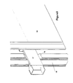
- Figure 1 shows a steel stud which, together with other studs (not shown), forms the basis for wall plates 2 and 3.
- the plates may be plaster plates, and it will be well-known that the use of plaster walls having two layers of plaster on both sides is becoming ever more popular. This is the most inexpensive possibility of achieving a greater strength and sound absorption.
- figure 1 shows a duct 4 having a duct connecting member 5 which has a reduced depth, measured transversely to the stud 1, relative to the duct 4.
- the depth of the duct connecting member 5 corresponds to the thickness of the plaster plate 2, which means that the external plate 3 terminates the wall and adjoins the duct 4, so that it is easy, by drilling through the plate 3, to get access to the duct 4 to mount e.g.
- the electrical installation equipment has a certain minimum mounting depth, and the invention is based on the circumstance that the duct depth corresponding thereto is much greater than is necessary to run wires and cables through the ducts.
- the depth of the duct connecting member is just sufficient for the necessary wiring to be run through.
- the plates 2 and 3 need not necessarily be of the same thickness, and by allowing the rear plate 3 to be relatively thicker than the front plate 3 the necessary space through the duct connecting member 5 may be achieved.
- the duct 4 and the duct connecting member 5 are interconnected e.g. by means of connecting flaps 6, which are adapted to cooperate with switching means in the ducts.
- Figure 2 shows a second embodiment, which uses wooden studs 7 and 8 that are formed with grooves for receiving a duct 9.
- the grooves are made so deep that the duct 9 will be flush with the outer side of the studs, thereby allowing a plate 10 to be mounted on the studs, said duct 9 adjoining the rear side of the plate 10.
- a connecting member for the duct 9 is indicated at 11.
- FIG 2 The embodiment shown in figure 2, in which there is no reduction of the duct 9, is based on the finding that the temporary weakening of the stud has no practical importance once the wall plates have been mounted, as the plates, in particular if a double layered covering is used, ensure that the wall has a sufficient strength.
- a metal plate 12 positioned in depressions 13 is shown in figure 2.
- the plates 12 may be secured by means of screws and impart a temporary strengthening to the wall as long as the wall plates have not been mounted, but primarily serve the purpose of making it impossible to screw screws through the duct 9 when the wall plates are mounted. This is particularly relevant if a further plate is arranged externally on the plate 10.
- Figure 3 shows a third embodiment which is something between the embodiments shown in figures 1 and 2.
- both stud and duct are reduced in depth in the area where the two structural parts are to pass each other.
- Figure 3 shows a steel stud 15 which has a depressed area 16 adapted to receive the reduced part of a duct connecting member 17. It is hereby possible to ensure that the wall plate 18 is flush with the duct and the stud, thereby also enabling a single layer covering to be made without having to weaken the stud 15 with a depression which is just as deep as is necessary in the part of the duct where it must be possible to mount electrical installation equipment.
- the depth reduction of the duct, the depression depth in the steel stud or the milling depth in the wooden stud may be adapted to each other and in dependence on whether a single layer or a multi-layered covering is used, and in dependence on the thickness of the rear plate.
- This provides a very flexible building system which may be adapted to all conditions, and thereby the system is also suitable for the renovation of existing building parts.
- Figure 4 shows a steel stud 19 whose width is locally reduced at 20.
- the reduction may be provided in the manufacture of the stud or by means of a tool at the building site.
Landscapes
- Engineering & Computer Science (AREA)
- Architecture (AREA)
- Civil Engineering (AREA)
- Structural Engineering (AREA)
- Load-Bearing And Curtain Walls (AREA)
Applications Claiming Priority (2)
| Application Number | Priority Date | Filing Date | Title |
|---|---|---|---|
| DKPA200001742 | 2000-11-20 | ||
| DK200001742 | 2000-11-20 |
Publications (1)
| Publication Number | Publication Date |
|---|---|
| EP1207607A1 true EP1207607A1 (fr) | 2002-05-22 |
Family
ID=8159856
Family Applications (1)
| Application Number | Title | Priority Date | Filing Date |
|---|---|---|---|
| EP01610119A Withdrawn EP1207607A1 (fr) | 2000-11-20 | 2001-11-20 | Système de contruction pour monter des canalisations cachées dans des cloisons |
Country Status (1)
| Country | Link |
|---|---|
| EP (1) | EP1207607A1 (fr) |
Cited By (3)
| Publication number | Priority date | Publication date | Assignee | Title |
|---|---|---|---|---|
| NL1033640C2 (nl) * | 2007-04-04 | 2008-10-07 | Infill Systems Bv | Werkwijze en systeem voor het onzichtbaar in een ruimte aanbrengen van bekabeling. |
| DE202008012477U1 (de) | 2008-09-19 | 2010-02-11 | Tehalit Gmbh | Befestigungsvorrichtung für Trockenbauwandkanäle |
| ES2361344A1 (es) * | 2011-01-26 | 2011-06-16 | Indíbil Batlle Serrano | Elemento prefabricado para la construcción de tabiques, revestimientos y similares, y procedimiento correspondiente. |
Citations (2)
| Publication number | Priority date | Publication date | Assignee | Title |
|---|---|---|---|---|
| US3553346A (en) * | 1969-06-04 | 1971-01-05 | Automated Building Components | Cable protector |
| US6098358A (en) * | 1997-05-15 | 2000-08-08 | Steelcase Development Inc. | Knock-down portable partition system |
-
2001
- 2001-11-20 EP EP01610119A patent/EP1207607A1/fr not_active Withdrawn
Patent Citations (2)
| Publication number | Priority date | Publication date | Assignee | Title |
|---|---|---|---|---|
| US3553346A (en) * | 1969-06-04 | 1971-01-05 | Automated Building Components | Cable protector |
| US6098358A (en) * | 1997-05-15 | 2000-08-08 | Steelcase Development Inc. | Knock-down portable partition system |
Cited By (6)
| Publication number | Priority date | Publication date | Assignee | Title |
|---|---|---|---|---|
| NL1033640C2 (nl) * | 2007-04-04 | 2008-10-07 | Infill Systems Bv | Werkwijze en systeem voor het onzichtbaar in een ruimte aanbrengen van bekabeling. |
| WO2008123771A1 (fr) * | 2007-04-04 | 2008-10-16 | Infill Systems B.V. | Procédé et système d'installation invisible de câblage dans une salle |
| US8713893B2 (en) | 2007-04-04 | 2014-05-06 | Infill Systems B.V. | Method and system for invisibly arranging cabling in a room |
| DE202008012477U1 (de) | 2008-09-19 | 2010-02-11 | Tehalit Gmbh | Befestigungsvorrichtung für Trockenbauwandkanäle |
| EP2166634A2 (fr) | 2008-09-19 | 2010-03-24 | Tehalit GmbH | Dispositif de fixation pour canaux muraux de la construction à sec |
| ES2361344A1 (es) * | 2011-01-26 | 2011-06-16 | Indíbil Batlle Serrano | Elemento prefabricado para la construcción de tabiques, revestimientos y similares, y procedimiento correspondiente. |
Similar Documents
| Publication | Publication Date | Title |
|---|---|---|
| US9273462B2 (en) | System and method of manufacture for building panels | |
| US6434890B1 (en) | Room enclosure comprised or prefabricated elements such as outer walls, partitions and intermediate floors or the like and a method for the assembly thereof | |
| US4800696A (en) | Premise wiring system for frame structures | |
| EP3631112B1 (fr) | Procédé de fabrication d'un renfoncement dans la région de base d'une construction de paroi et construction de paroi correspondante | |
| US5930960A (en) | Prefab wall element with integrated chases | |
| US3702044A (en) | Cavity shaft wall | |
| US20150176274A1 (en) | System and method for lateral transfer plate having a punched tab | |
| CN112696054A (zh) | 一种降噪工地房建筑结构 | |
| EP1221749B1 (fr) | Boîtier d'installation électrique à protection passive contre le feu | |
| KR19990019928U (ko) | 조립건물용 패널 | |
| KR20050046026A (ko) | 건축물의 경량 벽체 내화 구조 | |
| CN222632641U (zh) | 一种含有线盒的预制混凝土砌块及其生产模具、墙体结构 | |
| JP7565418B1 (ja) | スキップフロア用壁パネル | |
| JP7210470B2 (ja) | 特に水平建物構造を構成するための平坦な建物要素 | |
| KR19990036133U (ko) | 건축용 조립식 패널의 보강재 | |
| CN224106661U (zh) | 一种隔断墙 | |
| EP2585646A1 (fr) | Élément de construction, et procédé pour fabriquer un tel élément de construction. | |
| EP4077828B1 (fr) | Cloison sèche et procédé de construction d'une cloison sèche | |
| JP2592592B2 (ja) | 間仕切壁の施工方法 | |
| KR200317112Y1 (ko) | 건축용 벽돌 | |
| KR200268308Y1 (ko) | 간막이 벽체 시스템 | |
| JP3729898B2 (ja) | ユニット式建物 | |
| JP2561712Y2 (ja) | 耐火遮音間仕切壁 | |
| JP2004092199A (ja) | 高遮音複合壁 | |
| KR200343272Y1 (ko) | 건축물의 경량 벽체 내화 구조 |
Legal Events
| Date | Code | Title | Description |
|---|---|---|---|
| PUAI | Public reference made under article 153(3) epc to a published international application that has entered the european phase |
Free format text: ORIGINAL CODE: 0009012 |
|
| AX | Request for extension of the european patent |
Free format text: AL;LT;LV;MK;RO;SI |
|
| 17P | Request for examination filed |
Effective date: 20021111 |
|
| AKX | Designation fees paid |
Designated state(s): AT BE CH CY DE DK ES FI FR GB GR IE IT LI LU MC NL PT SE TR |
|
| AXX | Extension fees paid |
Extension state: LT Payment date: 20021111 Extension state: LV Payment date: 20021111 |
|
| RAP1 | Party data changed (applicant data changed or rights of an application transferred) |
Owner name: SCHNEIDER ELECTRIC DANMARK A/S |
|
| GRAP | Despatch of communication of intention to grant a patent |
Free format text: ORIGINAL CODE: EPIDOSNIGR1 |
|
| STAA | Information on the status of an ep patent application or granted ep patent |
Free format text: STATUS: THE APPLICATION IS DEEMED TO BE WITHDRAWN |
|
| 18D | Application deemed to be withdrawn |
Effective date: 20110712 |