EP1207618B1 - Schaltkreis zur Rückgewinnung von Geschwindigkeit eines Gleichstrommotors und Verfahren zum Benutzen dieses Schaltkreises - Google Patents
Schaltkreis zur Rückgewinnung von Geschwindigkeit eines Gleichstrommotors und Verfahren zum Benutzen dieses Schaltkreises Download PDFInfo
- Publication number
- EP1207618B1 EP1207618B1 EP00830764A EP00830764A EP1207618B1 EP 1207618 B1 EP1207618 B1 EP 1207618B1 EP 00830764 A EP00830764 A EP 00830764A EP 00830764 A EP00830764 A EP 00830764A EP 1207618 B1 EP1207618 B1 EP 1207618B1
- Authority
- EP
- European Patent Office
- Prior art keywords
- circuit
- speed
- voice coil
- current
- time period
- Prior art date
- Legal status (The legal status is an assumption and is not a legal conclusion. Google has not performed a legal analysis and makes no representation as to the accuracy of the status listed.)
- Expired - Lifetime
Links
- 238000011084 recovery Methods 0.000 title claims description 33
- 238000000034 method Methods 0.000 title claims description 25
- 101100478187 Arabidopsis thaliana MOS4 gene Proteins 0.000 claims description 11
- 101100461812 Arabidopsis thaliana NUP96 gene Proteins 0.000 claims description 11
- 238000001514 detection method Methods 0.000 claims description 8
- 102100030393 G-patch domain and KOW motifs-containing protein Human genes 0.000 claims description 7
- 229910052982 molybdenum disulfide Inorganic materials 0.000 claims description 7
- 101150090280 MOS1 gene Proteins 0.000 claims description 6
- 101100401568 Saccharomyces cerevisiae (strain ATCC 204508 / S288c) MIC10 gene Proteins 0.000 claims description 6
- 230000003213 activating effect Effects 0.000 claims description 5
- 101001009694 Homo sapiens G-patch domain and KOW motifs-containing protein Proteins 0.000 claims 1
- 238000010586 diagram Methods 0.000 description 11
- 230000001133 acceleration Effects 0.000 description 6
- 230000033001 locomotion Effects 0.000 description 6
- 238000005259 measurement Methods 0.000 description 4
- 238000009738 saturating Methods 0.000 description 2
- 238000004804 winding Methods 0.000 description 2
- 101710116852 Molybdenum cofactor sulfurase 1 Proteins 0.000 description 1
- 230000004913 activation Effects 0.000 description 1
- 230000003321 amplification Effects 0.000 description 1
- 238000003199 nucleic acid amplification method Methods 0.000 description 1
- 238000005070 sampling Methods 0.000 description 1
- 230000011664 signaling Effects 0.000 description 1
Images

Classifications
-
- H—ELECTRICITY
- H02—GENERATION; CONVERSION OR DISTRIBUTION OF ELECTRIC POWER
- H02P—CONTROL OR REGULATION OF ELECTRIC MOTORS, ELECTRIC GENERATORS OR DYNAMO-ELECTRIC CONVERTERS; CONTROLLING TRANSFORMERS, REACTORS OR CHOKE COILS
- H02P25/00—Arrangements or methods for the control of AC motors characterised by the kind of AC motor or by structural details
- H02P25/02—Arrangements or methods for the control of AC motors characterised by the kind of AC motor or by structural details characterised by the kind of motor
- H02P25/032—Reciprocating, oscillating or vibrating motors
- H02P25/034—Voice coil motors
Definitions
- the present invention refers to a circuit for the speed recovery of a direct current motor and method using said circuit, in particular for a Voice Coil Motor (VCM).
- VCM Voice Coil Motor
- a VCM is used for example to drive a mechanical arm on which the writing and/or reading heads for the data registered on a hard-disk are mounted.
- the VCM is capable of giving strong accelerations/decelerations to the mechanical arm that supports the head so as to minimize the track search time.
- the heads can reach a speed of the order of 2 ⁇ 2.54 m/sec.
- the output stage which drives the VCM in the event of losing power, is placed at high impedance so as to measure the speed of the motor through a value of the BEMF (Back Electromagnetic Force) generated by the same VCM.
- the value of the BEMF is memorized at the terminals of a capacity so that once, the sampling step of the BEMF is terminated, the braking action is executed by turning on the output stage again, that is by applying a voltage which has a value equal to that previously stored in the capacity but with an opposite sense so as to contrast the motion of the VCM. In this condition the capacity is unloaded through of a resistor, thus defining a time of duration of this speed recovery step.
- the output stage driving the VCM is placed in the so-called brake configuration, that is in a configuration wherein the low side transistors of the output bridge are placed in conduction. In this manner it is as if the VCM had its terminals in short circuit and it is therefore the VCM itself that generates a braking current. This condition of brake is held for a time which is determined by the discharge constant of a R - C circuit.
- PWM Pulse Width Modulation
- the effectiveness of the braking is not particularly energetic as the current must be zeroed periodically to be able to permit the measurement of the BEMF representing the speed of the VCM.
- US-A-6 140 784 discloses a circuit according to the pre-characterizing part of claim 1.
- the object of the present invention is to make a circuit for the efficient and controlled recovery of the speed of a direct current VCM type motor, in particular at the time the power voltage is disconnected after a search for a new track to be read and/or written has been actuated.
- a further object of the present invention is to supply a method capable of guaranteeing the efficient and controlled recovery of the speed of a VCM.
- this object is reached through a circuit for recovering the speed of a direct current motor as defined in claim 1.
- a circuit and a method can be provided which are capable of preventing the arm supporting the reading and/or writing heads from hitting at high speed against the end-of-stroke positions inside or outside the platters comprising the hard - disks.
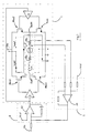
- FIG. 1 the circuit diagram is shown of a control bridge 1 for a direct current motor 2 of VCM type, which motor is represented by the series of an inductor Lm, of a resistor Rm and of a generator of BEMF.
- Bridge 1 comprises a first couple of N-channel MOS type power transistors, MOS1 and MOS2, called high side transistors, and a second couple of N-channel MOS type power transistors, MOS3 and MOS4, called low side transistors.
- the transistors MOS1 and MOS3 have respective gate electrodes controlled by a first driver 3, in addition, the source electrode of the MOS1 is connected with the drain electrode of the MOS3, so as to make an ouput terminal OutP, the drain electrode of the MOS1 is connected to a supply terminal Vm and the source electrode of the MOS3 is grounded.
- the transistors MOS2 and MOS4 have the respective gate electrodes controlled by a second driver 4, in addition, the source electrode of the MOS2 is connected with the drain electrode of the MOS4, so as to make an output terminal OutM, the drain electrode of the MOS2 is connected to the supply terminal Vm and the source electrode of the MOS4 is grounded.
- a voltage is developed which is read by a first block 5 comprising an operational amplifier A1, called sense amplifier.
- the amplifier A1 amplifies the voltage which develops at the terminals of Rs.
- Said amplifier A1 also has in input a reference voltage Vref which represents the working point of the whole current loop.
- the bridge 1 is controlled by the inputs of the drivers 3 and 4, according to methods known to a technician in the art.
- VCM 2 is driven by means of the bridge 1 functioning in class AB, and during the steps of searching for the tracks and of reading and/or writing, the movement of the VCM 2 is current controlled, in accordance with the diagram of Figure 1.
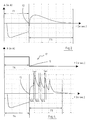
- the braking current Ivcm2 which is supplies by VCM 2 depends on the contribution of the voltage Vm that supplies the output stage plus the contribution given by the generator of BEMF that the motor itself generates as it has the same polarity.
- an X-axis indicating the time, expressed in milliseconds, and a Y-axis indicating the current, expressed in milliamperes, can be seen.
- the motor 2 that generates a braking action as shown during the second period T3.
- the BEMF generated by the speed of the motor 2 during the acceleration phase, period T1 is capable of pushing a current with such a direction to oppose the motion of the motor itself.
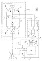
- Figure 3 is shown a circuit diagram used for the control of the current in a VCM in applications for hard - disk according to the present invention.
- a block 7 representing the circuitry for the speed recovery comprising a timing generator block 8 and a comparator 9, and also a switch S 1 can be seen suitable for selectively connecting a positive voltage, Vin+, or a negative voltage , Vin-.
- the block 7 receives two input signals, 10 and 11: the signal 10 is the output voltage of the amplifier A1 which is compared by means of the comparator 9 with two input thresholds Spd+ and Spd-. Said thresholds represent respectively the minimum speed at which the braking procedure is to be interrupted, in the case of clockwise and anti-clockwise rotation, respectively; the signal 11 is generated by a circuitry (not shown in the Figure) capable of signaling the loss of the supply voltage of the motor 2 to timing block 8 also called POR (Power On Reset).
- POR Power On Reset
- the comparator 9 is a window comparator having a double trip threshold and generates in output a first signal 12, representing the rotation direction of the motor 2, and a second signal 13, indicating that the motor 2 is turning beyond a determined speed.
- the time generator 8 receives said signals 11, 12 and 13 in input and generates a first signal 14, representing a braking period Tbrk, a second signal 15, representing an activation period Tact, and a third signal 16, representing the end of the speed recovery procedure.
- the last signal 16 is generated once the amplifier 9 detects that the speed of the VCM 2 has returned from the interval defined by the thresholds Spd- and Spd+, or that the speed has reached zero.
- the signal 15 commands the switch S1 for the period Tact in function of the rotation direction of the motor.
- S1 connects to the positive voltage Vin+ for all Tact if the rotation is clockwise while it connects to the negative voltage Vin- for all Tact if the rotation is anti-clockwise.
- the circuitry of the block 7 therefore detects the speed of VCM 2 at the time the supply is lost, for the whole duration of the braking procedure, and executes the generation of the periods Tbrk and Tact in such a manner as to command the bridge 1 turning on the diagonal of the output stage 1 in accordance with the direction that the current has to have to brake the motor, 2 duly commutating switch S1.
- motor 2 in the brake condition, that is when there is a loss of supply, if motor 2 is rotating at a certain speed, and is thus generating a BEMF, and therefore motor 2 is capable of pushing a current that opposes the motion immediately activating a braking step for a determined period Tbrk., higher is the speed reached by the motor before the loss of supply voltage, greater is the braking action during the brake functioning.
- the inventive system measures the BEMF generated by motor 2 by means of block 7.
- the system evaluates if motor 2 is rotating beyond a given speed and in which direction as it measures the voltage in output from amplifier A1, that is it measures the voltage present on line 10. This is possible because the current Ivcm is directly proportional to the BEMF, in accordance with the equation (2).
- the comparator 9 generates the signals 12 and 13, indicating respectively the rotation direction and if the speed of motor 2 is outside the interval Spd+ and Spd-, so that the timing block 8 generates the signal 15 so as to activate the diagonal of the output stage 1, for a predetermined period Tact, driving the current Ivcm in the correct direction to brake the motor 2, which current has the same direction but a greater value compared to the current present during the brake phase.
- the potential applied to the terminals of motor 2 is the sum of the voltage at the terminals of the output stage 1 and of the BEMF (BEMF generated by the motor in motion).
- an X-axis indicating the time, expressed in milliseconds, and a Y-axis indicating the current, expressed in milliamperes, can be seen.
- the instant t5 indicates the moment at which there is the loss of supply voltage and the signal 17 goes to zero thus activating block 7, period T5.
- the output stage 1 is placed in brake condition, in which the BEMF of the motor 2 pushes a braking current in the motor 2 itself for a period Tbrk.
- Tbrk the width and the direction of the current pushed by motor 2 are monitored by means of the double trip threshold comparator 9.
- the output stage 1 is driven saturating the two transistors MOS of the diagonal opposite that previously functioning for a period Tact.
- the comparator 9 In the event the braking procedure is required to be terminated with motor 2 stopped, the comparator 9 must be made with only one trip threshold Sref (not shown in the Figure) representing the motor stop condition, also called zero motion.
- Figure 5 shows a block diagram of the procedure for the speed recovery of a VCM according to the present invention.
- an initial block 40 can be noted followed by a first test block 18 on the signal 17 to check if said signal 17 is active or not. If negative, that is signal 17 active, branch 38, test 18 is again executed, while if positive, that is signal 17 equal to zero, branch 39, the brake condition is activated for a period Tbrk, block 19, that is there is a situation of loss of supply.
- test block 20 Successively a second test block 20 is executed to check if said period Tbrk has passed. If negative, branch 30, the test 20 is executed again while if affirmative, branch 29, the rotation speed of the VCM 2 is read, block 21, by means of the sense amplifier A1.
- branch 32 block 28 is executed so as to generate the signal 16 of end of procedure and to end the program, block 42.
- branch 33 block 24 is executed, that is switch S 1 is connected to the positive voltage Vin+ for a period Tact, while if the direction is anti-clockwise, branch 34, block 25 is executed, that is switch S 1 is connected to the negative voltage Vin- for a period Tact.
- Both blocks 24 and 25 activate a further block 26 so that the output stage 1 is driven saturating the two MOS of the diagonal of the output bridge 1 so as to force current in the same direction as the brake step.
- test 27 Successively a fifth test 27 is executed to check if the period Tact has passed. If negative, branch 36, test 27 is again executed, while if positive, branch 37, the cycle starts again from the brake condition 19.
- the periods Tbrk and Tact can be defined by the user so as to guarantee greater flexibility to the circuit and to the inventive method.
- One possible alternative embodiment is to carry out the control of the current during the step in which a diagonal of the output stage 1 is activated.
- the diagonal of the bridge 1 must be kept enabled until the current in motor 2 reaches a set value, after which it is completed and the step is carried out as previously illustrated.
Landscapes
- Engineering & Computer Science (AREA)
- Power Engineering (AREA)
- Control Of Direct Current Motors (AREA)
- Control Of Linear Motors (AREA)
- Moving Of Head For Track Selection And Changing (AREA)
Claims (12)
- Schaltung zur Rückgewinnung von Geschwindigkeit eines Schwingspulenmotors mit:einer Ausgangsstufe (1) mit einem ersten Paar an Transistoren (MOS1, MOS2) und einem zweiten Paar an Transistoren (MOS3, MOS4), undein Erfassungsmittel (5) zum Erfassen eines ersten Stroms (Ivcm), der in dem Motor (2) fließt,gekennzeichnet durch ein zweites Mittel (7) zum Aktivieren des zweiten Paars von Transistoren (MOS3, MOS4) der Ausgangsstufe (1) für eine erste Zeitspanne (Tbrk), um so den Motor (2) kurzzuschließen, und wobei am Ende der ersten Zeitspanne (Tbrk) das zweite Mittel (7) geeignet ist zum aus dem Gleichgewichtbringen der Ausgangsstufe (1), um so einen zweiten Strom (Ivcm) zu erzwingen, der größer ist als der erste Strom, für eine vorbestimmte zweite Zeitspanne (Tact) gemäß dem Wert, der von dem Erfassungsmittel (5) während der ersten Zeitspanne (Tbrk) erfaßt ist.
- Schaltung zur Rückgewinnung von Geschwindigkeit eines Schwingspulenmotors nach Anspruch 1, dadurch gekennzeichnet, daß das zweite Mittel (7) umfaßt: einen Vergleicher (9) zum Erzeugen eines Richtungssignals (12) und eines Geschwindigkeitssignals (13) sowie einen Zeitschalter (8), der geeignet ist, die Ausgangsstufe (1) für die erste Zeitspanne (Tbrk) derart anzutreiben, daß ein Schalter (S1) für die zweite Zeitspanne (Tact) angesteuert ist und daß ein Verfahrensendsignal (16) erzeugt ist.
- Schaltung zur Rückgewinnung von Geschwindigkeit eines Schwingspulenmotors nach Anspruch 2, dadurch gekennzeichnet, daß der Schalter (S1) die Ausgangsstufe (1) wahlweise an eine positive (Vin+) oder negative (Vin-) Spannungsleitung für die zweite Zeitspanne (Tact) verbindet.
- Schaltung zur Rückgewinnung von Geschwindigkeit eines Schwingspulenmotors nach Anspruch 2, dadurch gekennzeichnet, daß der Vergleicher (9) an dem Eingang ein Paar von Referenzsignalen (Spd+, Spd-) und ein von dem Erfassungsmittel (5) erzeugtes (10) Signal empfängt sowie am Ausgang ein Paar von Signalen (12, 13) erzeugt, die geeignet sind zum Anzeigen des Überschreitens einer vorbestimmten Rotationsgeschwindigkeit und des Rotationssinns des Motors (2).
- Schaltung zur Rückgewinnung von Geschwindigkeit eines Schwingspulenmotors nach Anspruch 4, dadurch gekennzeichnet, daß die Referenzsignale (Spd+, Spd-) die minimale Geschwindigkeit wiedergeben, bei der der Motor (2) gestoppt wird.
- Schaltung zur Rückgewinnung von Geschwindigkeit eines Schwingspulenmotors nach Anspruch 4, dadurch gekennzeichnet, daß die Referenzsignale (Spd+, Spd-) durch den Anwender definiert werden können.
- Schaltung zur Rückgewinnung von Geschwindigkeit eines Schwingspulenmotors nach Anspruch 4, dadurch gekennzeichnet, daß der Vergleicher (9) am Eingang ein einzelnes Referenzsignal (Sref) und das Signal (10) empfängt, das durch das Erfassungsmittel (5) erzeugt ist, sowie am Ausgang ein Paar von Signalen (12, 13) erzeugt, die geeignet sind zum Anzeigen des Übersteigens einer vorbestimmten Rotationsgeschwindigkeit und des Rotationssinns des Motors (2).
- Schaltung zur Rückgewinnung von Geschwindigkeit eines Schwingspulenmotors nach Anspruch 2, dadurch gekennzeichnet, daß der Zeitschalter (8) am Eingang die zwei von dem Vergleicher (9) erzeugten Signale (12, 13) und ein Signal des Ausfalls der Versorgungsspannung (11) empfängt, und daß die Zeitschalterschaltung (8) die erste Zeitspanne (Tbrk) und die zweite Zeitspanne (Tact) als eine Funktion der von dem Vergleicher (9) erzeugten Signale (12, 13) ausführt.
- Schaltung zur Rückgewinnung von Geschwindigkeit eines Schwingspulenmotors nach einem der vorhergehenden Ansprüche, dadurch gekennzeichnet, daß das Erfassungsmittel (5) einen Erfassungswiderstand (Rs) und einen Operationsverstärker (A1) umfaßt.
- Schaltung zur Rückgewinnung von Geschwindigkeit eines Schwingspulenmotors nach Anspruch 9, dadurch gekennzeichnet, daß der Operationsverstärker (A1) die Eingangsspannung an den Anschlüssen des Erfassungswiderstands (Rs) und ein Spannungsreferenzsignal (Vref) empfängt, um so ein Signal (10) zu erzeugen, das geeignet ist zum Messen des Stroms, den der Motor (2) erzeugt.
- Schaltung zur Rückgewinnung von Geschwindigkeit eines Schwingspulenmotors nach einem der vorhergehenden Ansprüche, dadurch gekennzeichnet, daß die Ausgangsstufe (1) mit N-Kanal-MOSFET-Typ-Leistungstransistoren (MOS1, MOS2, MOS3, MOS4) ausgeführt ist, die in AB-Konfiguration angeordnet sind.
- Verfahren zur Rückgewinnung von Geschwindigkeit eines Schwingspulenmotors, dadurch gekennzeichnet, daß es die folgende Folge von Schritten umfaßt:a) Überprüfen, ob es einen Ausfall der Versorgungsspannung gibt;b) Kurzschließen eines ersten Paars von Transistoren (MOS3, MOS4) für eine erste Zeitspanne (Tbrk);c) Messen eines Stroms (Ivcm), der proportional der Drehgeschwindigkeit des Motors (2) ist;d) Messen der Polarität des Stroms (Ivcm), wodurch die Rotationsrichtung des Motors (2) bestimmt wird;e) Erzwingen eines Stroms (Ivcm) von größerer Intensität als der während den Schritten (c) und (d) gemessene und mit einer gleichen Polarität für eine zweite Zeitspanne (Tact) in dem Motor (2);f) Wiederholen der Schritte (b), (c), (d) und (e), bis der Strom (Icvm) zu einem vorbestimmten Meßintervall (Spd-; Spd+) zurückkehrt;g) Erzeugen eines Verfahrensendsignals (16).
Priority Applications (4)
| Application Number | Priority Date | Filing Date | Title |
|---|---|---|---|
| DE60023014T DE60023014D1 (de) | 2000-11-20 | 2000-11-20 | Schaltkreis zur Rückgewinnung von Geschwindigkeit eines Gleichstrommotors und Verfahren zum Benutzen dieses Schaltkreises |
| EP00830764A EP1207618B1 (de) | 2000-11-20 | 2000-11-20 | Schaltkreis zur Rückgewinnung von Geschwindigkeit eines Gleichstrommotors und Verfahren zum Benutzen dieses Schaltkreises |
| US09/988,911 US6680598B2 (en) | 2000-11-20 | 2001-11-19 | Circuit for the speed recovery of a direct current motor and method using said circuit |
| JP2001354965A JP2002223588A (ja) | 2000-11-20 | 2001-11-20 | 直流電流モータの速度回復回路 |
Applications Claiming Priority (1)
| Application Number | Priority Date | Filing Date | Title |
|---|---|---|---|
| EP00830764A EP1207618B1 (de) | 2000-11-20 | 2000-11-20 | Schaltkreis zur Rückgewinnung von Geschwindigkeit eines Gleichstrommotors und Verfahren zum Benutzen dieses Schaltkreises |
Publications (2)
| Publication Number | Publication Date |
|---|---|
| EP1207618A1 EP1207618A1 (de) | 2002-05-22 |
| EP1207618B1 true EP1207618B1 (de) | 2005-10-05 |
Family
ID=8175556
Family Applications (1)
| Application Number | Title | Priority Date | Filing Date |
|---|---|---|---|
| EP00830764A Expired - Lifetime EP1207618B1 (de) | 2000-11-20 | 2000-11-20 | Schaltkreis zur Rückgewinnung von Geschwindigkeit eines Gleichstrommotors und Verfahren zum Benutzen dieses Schaltkreises |
Country Status (4)
| Country | Link |
|---|---|
| US (1) | US6680598B2 (de) |
| EP (1) | EP1207618B1 (de) |
| JP (1) | JP2002223588A (de) |
| DE (1) | DE60023014D1 (de) |
Families Citing this family (12)
| Publication number | Priority date | Publication date | Assignee | Title |
|---|---|---|---|---|
| JP2003059216A (ja) * | 2001-08-16 | 2003-02-28 | Internatl Business Mach Corp <Ibm> | ハード・ディスク・ドライブ、データ記憶再生装置、ヘッド移動制御装置およびヘッド移動制御方法 |
| DE10226152A1 (de) * | 2002-06-13 | 2003-12-24 | Deere & Co | Schaltungsanordnung zum Betreiben eines Gleichstrommotors und Verstelleinrichtung mit einer solchen |
| KR100652436B1 (ko) * | 2005-10-11 | 2006-12-01 | 삼성전자주식회사 | 하드디스크 드라이브의 레퍼런스 서보 신호 기록 방법 및이에 적합한 장치 |
| WO2007121189A2 (en) * | 2006-04-10 | 2007-10-25 | Texas Instruments Incorporated | On-chip compensation for a fully differential voice coil motor control |
| TW200744304A (en) * | 2006-05-16 | 2007-12-01 | Wiz Energy Technology Company | Electronic brake and energy recycling system applied in brushless DC motor |
| CN101085602A (zh) * | 2006-06-07 | 2007-12-12 | 宇泉能源科技股份有限公司 | 使用于无刷直流马达的电子刹车暨能源回收系统 |
| KR100734329B1 (ko) * | 2006-07-24 | 2007-07-02 | 삼성전자주식회사 | 서보패턴 카피를 위한 서보패턴 탐색 방법 |
| TWI398090B (zh) * | 2009-11-11 | 2013-06-01 | Princeton Technology Corp | 應用於複數種控制模式之馬達控制電路 |
| DE102010032335A1 (de) * | 2010-07-20 | 2012-01-26 | C. & E. Fein Gmbh | Handwerkzeug |
| JP6198447B2 (ja) * | 2013-04-26 | 2017-09-20 | ローム株式会社 | ボイスコイルモータの駆動回路およびそれを用いたレンズモジュールおよび電子機器 |
| TWI571025B (zh) * | 2016-01-21 | 2017-02-11 | 旺玖科技股份有限公司 | 負電壓保護系統 |
| EP4145697A1 (de) * | 2021-09-01 | 2023-03-08 | Braun GmbH | Motoreinheit und körperpflegevorrichtung mit einer motoreinheit |
Family Cites Families (19)
| Publication number | Priority date | Publication date | Assignee | Title |
|---|---|---|---|---|
| US3786329A (en) * | 1973-01-31 | 1974-01-15 | Kollmorgen Corp | Dynamic brake |
| JPS5620395U (de) * | 1979-07-23 | 1981-02-23 | ||
| US4545004A (en) * | 1984-03-22 | 1985-10-01 | General Motors Corporation | Bridge driver circuit for a DC electric motor |
| US5423192A (en) * | 1993-08-18 | 1995-06-13 | General Electric Company | Electronically commutated motor for driving a compressor |
| JPH062316U (ja) * | 1992-06-12 | 1994-01-14 | 株式会社ニコン | カメラ及びそのアクセサリーに使用されるモータ駆動装置 |
| KR100295029B1 (ko) * | 1992-11-17 | 2001-10-24 | 요트.게.아. 롤페즈 | 모터구동회로 |
| JP3545049B2 (ja) * | 1993-06-22 | 2004-07-21 | エスティーマイクロエレクトロニクス,インコーポレイテッド | 電源エネルギ障害時の逆起電力整流電圧 |
| DE69427292D1 (de) * | 1994-07-19 | 2001-06-28 | Sgs Thomson Microelectronics | Bidirektionale Stromabfühlschaltung für eine H-Brücke |
| US5631527A (en) * | 1994-09-06 | 1997-05-20 | Sgs-Thomson Microelectronics, Inc. | Voice coil motor feedback control circuit |
| JPH098566A (ja) * | 1995-06-06 | 1997-01-10 | Sgs Thomson Microelectron Inc | 増幅器出力段 |
| JPH0923688A (ja) * | 1995-06-29 | 1997-01-21 | Sgs Thomson Microelectron Inc | ブラシレスdcモータ用パワーダウン制動ラッチ |
| US5737144A (en) * | 1996-06-05 | 1998-04-07 | Quantum Corporation | Switched boost voltage generator for actuator retract in disk drive |
| JP3114800B2 (ja) * | 1997-06-30 | 2000-12-04 | 日本電気株式会社 | モータ駆動回路 |
| DE69704709T2 (de) * | 1997-10-23 | 2001-08-09 | Stmicroelectronics S.R.L., Agrate Brianza | Integriertes Antriebssystem für Pulsbreitenmodulation in Strombetriebsart |
| US6160368A (en) * | 1998-06-22 | 2000-12-12 | Western Digital Corporation | Faster spin-down operation in a disk drive by utilizing pulsed braking |
| US6229273B1 (en) * | 1999-02-23 | 2001-05-08 | Lucent Technologies, Inc. | Actuator driver circuit |
| US6140784A (en) * | 1999-06-09 | 2000-10-31 | Quantum Corporation | Power off velocity control for disk drives |
| US6369534B1 (en) * | 2000-04-26 | 2002-04-09 | Stmicroelectronics, Inc. | Circuit and method for detecting backward spin of a spindle motor for a disk drive |
| US6353298B1 (en) * | 2001-04-11 | 2002-03-05 | Texas Instruments Incorporated | Low distortion audio range class-AB full H-bridge pre-driver amplifier |
-
2000
- 2000-11-20 EP EP00830764A patent/EP1207618B1/de not_active Expired - Lifetime
- 2000-11-20 DE DE60023014T patent/DE60023014D1/de not_active Expired - Lifetime
-
2001
- 2001-11-19 US US09/988,911 patent/US6680598B2/en not_active Expired - Lifetime
- 2001-11-20 JP JP2001354965A patent/JP2002223588A/ja active Pending
Also Published As
| Publication number | Publication date |
|---|---|
| DE60023014D1 (de) | 2005-11-10 |
| US20020081106A1 (en) | 2002-06-27 |
| US6680598B2 (en) | 2004-01-20 |
| JP2002223588A (ja) | 2002-08-09 |
| EP1207618A1 (de) | 2002-05-22 |
Similar Documents
| Publication | Publication Date | Title |
|---|---|---|
| EP1207618B1 (de) | Schaltkreis zur Rückgewinnung von Geschwindigkeit eines Gleichstrommotors und Verfahren zum Benutzen dieses Schaltkreises | |
| CN106887980A (zh) | 确定永磁电机的停靠位置 | |
| US20060181237A1 (en) | Method of stall detection for stepper motor system | |
| JP4684763B2 (ja) | 静止位置検出回路 | |
| US6631045B1 (en) | Method and apparatus for ramp loading in a hard disk drive using pulse width modulation | |
| US12180767B2 (en) | Open/close control device, open/close control system, open/close control method, and program | |
| KR20180046380A (ko) | 컨택터를 위한 제어 시스템 | |
| JP4811859B2 (ja) | 磁気ディスク制御方法と磁気ディスク制御装置 | |
| JP2002354893A (ja) | ステップモータの回転制御装置 | |
| CN106208843B (zh) | 电动机驱动电路、振动装置以及电子设备 | |
| JP2001136771A (ja) | モータの駆動装置 | |
| JP2010035312A (ja) | Dcモータ制御装置 | |
| JP2002199791A (ja) | 電流検出回路及びこれを備えたモータ制御装置 | |
| JP2002174075A (ja) | 開閉制御装置 | |
| JPS5899276A (ja) | モ−タのブレ−キ装置 | |
| US20260100200A1 (en) | Method of operating hard disk drives, corresponding control circuit, hard disk drive and processing device | |
| JPS59177767A (ja) | アクセス制御回路 | |
| JP7576971B2 (ja) | 移動体の位置検出装置、モータの回転量検出装置 | |
| JPH04222970A (ja) | 磁気ディスク装置 | |
| JP2000087645A (ja) | パワーウインド装置 | |
| JP2551836B2 (ja) | 駆動制御装置 | |
| EP0426447A2 (de) | Spursprungsteuerungsschaltung | |
| JPH0440793B2 (de) | ||
| JPH11126412A (ja) | 回転型記憶装置 | |
| KR950000049B1 (ko) | 전원단전시 디스크드라이브장치의 스핀들모터제동 및 헤드파킹제어회로 |
Legal Events
| Date | Code | Title | Description |
|---|---|---|---|
| PUAI | Public reference made under article 153(3) epc to a published international application that has entered the european phase |
Free format text: ORIGINAL CODE: 0009012 |
|
| AX | Request for extension of the european patent |
Free format text: AL;LT;LV;MK;RO;SI |
|
| 17P | Request for examination filed |
Effective date: 20021113 |
|
| AKX | Designation fees paid |
Designated state(s): DE FR GB IT |
|
| 17Q | First examination report despatched |
Effective date: 20040616 |
|
| GRAP | Despatch of communication of intention to grant a patent |
Free format text: ORIGINAL CODE: EPIDOSNIGR1 |
|
| GRAS | Grant fee paid |
Free format text: ORIGINAL CODE: EPIDOSNIGR3 |
|
| GRAA | (expected) grant |
Free format text: ORIGINAL CODE: 0009210 |
|
| AK | Designated contracting states |
Kind code of ref document: B1 Designated state(s): DE FR GB IT |
|
| REG | Reference to a national code |
Ref country code: GB Ref legal event code: FG4D |
|
| REF | Corresponds to: |
Ref document number: 60023014 Country of ref document: DE Date of ref document: 20051110 Kind code of ref document: P |
|
| PG25 | Lapsed in a contracting state [announced via postgrant information from national office to epo] |
Ref country code: DE Free format text: LAPSE BECAUSE OF FAILURE TO SUBMIT A TRANSLATION OF THE DESCRIPTION OR TO PAY THE FEE WITHIN THE PRESCRIBED TIME-LIMIT Effective date: 20060106 |
|
| PLBE | No opposition filed within time limit |
Free format text: ORIGINAL CODE: 0009261 |
|
| STAA | Information on the status of an ep patent application or granted ep patent |
Free format text: STATUS: NO OPPOSITION FILED WITHIN TIME LIMIT |
|
| 26N | No opposition filed |
Effective date: 20060706 |
|
| PG25 | Lapsed in a contracting state [announced via postgrant information from national office to epo] |
Ref country code: FR Free format text: LAPSE BECAUSE OF FAILURE TO SUBMIT A TRANSLATION OF THE DESCRIPTION OR TO PAY THE FEE WITHIN THE PRESCRIBED TIME-LIMIT Effective date: 20061020 |
|
| EN | Fr: translation not filed | ||
| PGFP | Annual fee paid to national office [announced via postgrant information from national office to epo] |
Ref country code: IT Payment date: 20071117 Year of fee payment: 8 |
|
| PG25 | Lapsed in a contracting state [announced via postgrant information from national office to epo] |
Ref country code: FR Free format text: LAPSE BECAUSE OF FAILURE TO SUBMIT A TRANSLATION OF THE DESCRIPTION OR TO PAY THE FEE WITHIN THE PRESCRIBED TIME-LIMIT Effective date: 20051130 |
|
| PG25 | Lapsed in a contracting state [announced via postgrant information from national office to epo] |
Ref country code: FR Free format text: LAPSE BECAUSE OF FAILURE TO SUBMIT A TRANSLATION OF THE DESCRIPTION OR TO PAY THE FEE WITHIN THE PRESCRIBED TIME-LIMIT Effective date: 20051005 |
|
| PG25 | Lapsed in a contracting state [announced via postgrant information from national office to epo] |
Ref country code: IT Free format text: LAPSE BECAUSE OF NON-PAYMENT OF DUE FEES Effective date: 20081120 |
|
| PGFP | Annual fee paid to national office [announced via postgrant information from national office to epo] |
Ref country code: GB Payment date: 20101026 Year of fee payment: 11 |
|
| GBPC | Gb: european patent ceased through non-payment of renewal fee |
Effective date: 20121120 |
|
| PG25 | Lapsed in a contracting state [announced via postgrant information from national office to epo] |
Ref country code: GB Free format text: LAPSE BECAUSE OF NON-PAYMENT OF DUE FEES Effective date: 20121120 |