EP1208822A2 - Vorrichtung zur medizinischen Versorgung von Gelenkverletzungen - Google Patents
Vorrichtung zur medizinischen Versorgung von Gelenkverletzungen Download PDFInfo
- Publication number
- EP1208822A2 EP1208822A2 EP01127583A EP01127583A EP1208822A2 EP 1208822 A2 EP1208822 A2 EP 1208822A2 EP 01127583 A EP01127583 A EP 01127583A EP 01127583 A EP01127583 A EP 01127583A EP 1208822 A2 EP1208822 A2 EP 1208822A2
- Authority
- EP
- European Patent Office
- Prior art keywords
- joint
- stabilizing
- coupling element
- elements
- coupling
- Prior art date
- Legal status (The legal status is an assumption and is not a legal conclusion. Google has not performed a legal analysis and makes no representation as to the accuracy of the status listed.)
- Withdrawn
Links
Images


Classifications
-
- A—HUMAN NECESSITIES
- A61—MEDICAL OR VETERINARY SCIENCE; HYGIENE
- A61F—FILTERS IMPLANTABLE INTO BLOOD VESSELS; PROSTHESES; DEVICES PROVIDING PATENCY TO, OR PREVENTING COLLAPSING OF, TUBULAR STRUCTURES OF THE BODY, e.g. STENTS; ORTHOPAEDIC, NURSING OR CONTRACEPTIVE DEVICES; FOMENTATION; TREATMENT OR PROTECTION OF EYES OR EARS; BANDAGES, DRESSINGS OR ABSORBENT PADS; FIRST-AID KITS
- A61F5/00—Orthopaedic methods or devices for non-surgical treatment of bones or joints; Nursing devices ; Anti-rape devices
- A61F5/01—Orthopaedic devices, e.g. long-term immobilising or pressure directing devices for treating broken or deformed bones such as splints, casts or braces
- A61F5/0102—Orthopaedic devices, e.g. long-term immobilising or pressure directing devices for treating broken or deformed bones such as splints, casts or braces specially adapted for correcting deformities of the limbs or for supporting them; Ortheses, e.g. with articulations
- A61F5/0123—Orthopaedic devices, e.g. long-term immobilising or pressure directing devices for treating broken or deformed bones such as splints, casts or braces specially adapted for correcting deformities of the limbs or for supporting them; Ortheses, e.g. with articulations for the knees
- A61F5/0125—Orthopaedic devices, e.g. long-term immobilising or pressure directing devices for treating broken or deformed bones such as splints, casts or braces specially adapted for correcting deformities of the limbs or for supporting them; Ortheses, e.g. with articulations for the knees the device articulating around a single pivot-point
-
- A—HUMAN NECESSITIES
- A61—MEDICAL OR VETERINARY SCIENCE; HYGIENE
- A61F—FILTERS IMPLANTABLE INTO BLOOD VESSELS; PROSTHESES; DEVICES PROVIDING PATENCY TO, OR PREVENTING COLLAPSING OF, TUBULAR STRUCTURES OF THE BODY, e.g. STENTS; ORTHOPAEDIC, NURSING OR CONTRACEPTIVE DEVICES; FOMENTATION; TREATMENT OR PROTECTION OF EYES OR EARS; BANDAGES, DRESSINGS OR ABSORBENT PADS; FIRST-AID KITS
- A61F13/00—Bandages or dressings; Absorbent pads
- A61F13/06—Bandages or dressings; Absorbent pads specially adapted for feet or legs; Corn-pads; Corn-rings
- A61F13/061—Bandages or dressings; Absorbent pads specially adapted for feet or legs; Corn-pads; Corn-rings for knees
Definitions
- the invention relates to a device for the medical care of joint injuries, with at least one at least two stabilizing elements articulated to one another having joint and at least one on at least one of the Stabilizing elements attached and an adjacent to the joint to be supplied Body member at least partially encircling, preferably rigid coupling element.
- Such devices are used, for example, in the form of so-called orthoses for medical purposes Treatment of knee injuries used.
- These knee braces can be used in the preoperative and postoperative phase as well as in rehabilitation and prophylaxis be used.
- they are articulated with one another connected stabilizing elements for rotational stabilization of the at least one coupling element coupled thereto, adjacent to the joint to be supplied Limbs of the body when the joint to be supplied is stressed.
- the purpose of the stabilizing elements of known knee orthoses is usually one Assigned limiting device with which the pivoting movement of the one stabilizing element with respect to the other stabilizing element about the hinge axis can be limited. In cooperation with the coupling element, there can be a limitation the flexion and extension of the joint to be treated can be achieved.
- the invention is based on the object to provide a device for medical care of joint injuries, with the undesirable loads of the joint to be supplied reliably can be prevented.
- this object is achieved by developing the known devices solved, which is essentially characterized in that the location of the Coupling element is adjustable with respect to the hinge axis.
- the adjustment of the position of the coupling elements with respect to the axis of the joint can also be made if the coupling elements are captive are attached to the stabilizing elements and adjustment by displacement of the coupling elements along the stabilizing elements in a perpendicular to Joint axis extending direction is made, it has with regard to the Obtaining a particularly good adaptation of the device according to the invention to the respective Operating conditions proved to be particularly advantageous if at least one coupling element is detachably connected to the at least one stabilizing element.
- an exchange of coupling elements can be made. That can for example, be required if the shape of the coupling element is none allows satisfactory coupling to and from the corresponding limb Because a differently shaped coupling element must be used.
- At least one of the joints can be assigned a limiting device with which one Pivotal movement of one stabilizing element with respect to the other stabilizing element is limited around the axis of the joint so as to limit flexion and Extension of the limbs coupled to the joints via the coupling elements to reach.
- a device according to the invention can also other functional elements, such as a joint to be supplied and / or at least one limb adjacent to the joint to be treated circumferential, preferably detachable with one of the stabilizing elements and / or the have at least one coupling element connected compression device.
- a compression device for example in the form of a bandage element can be used to counteract swelling and / or stimulation the sensorimotor system in the area of the joint to be supplied.
- the detachable connection can be particularly advantageous Embodiment of the invention made using surface fasteners become.
- the compression device When used in particular for the care of knee injuries
- the compression device also has a device in addition to a bandage body at least one gel insert, which adapts particularly well to the respective joint shape adapts.
- a gel insert for example, the patella can be stabilized and counteracting patellar lateralization.
- the bandage body of a device according to the invention can, for example, in Form of a textile laminate.
- a device according to the invention with at least one at least two articulated joint having stabilizing elements, at least a coupling element connected to at least one stabilizing element and at least one connected to the joint and / or the coupling element Compression device to the respective conditions of use can be achieved if all connections between the stabilizing element, the coupling element and the Compression device can be solved because of the modularity of the overall device achieved in this way all elements to obtain an ideal adaptation to the respective operating conditions can be exchanged.
- at least one coupling element is at least partially made of thermoplastic Plastic is made.
- the coupling element can also be parts have made of fiber-reinforced plastic in order to obtain a particularly high stability.
- the stabilizing element of the device according to the invention can be made of aluminum, Carbon and / or glass fibers exist.
- the stabilizing elements can Device according to the invention anatomically preformed in a particularly advantageous embodiment his.
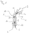
- the device shown in Fig. 1 is for post-operative treatment in the event of injury of the anterior cruciate ligament.
- This device comprises two joints 10, one of which 1, however, only one is shown, as well as two coupling elements 20 and 22.
- the joints 10 are arranged medially and laterally and via the coupling elements 20 and 22 connected together.
- Each of the joints 10 comprises two in the form of joint rails 12 and 14 formed stabilizing elements, of which the hinge rail 12th runs approximately parallel to the femur 2, while the joint splint 14 approximately runs parallel to the lower leg bones (tibia 4 and fibula 6).
- the coupling element 14 runs dorsally around the thigh, while the joint splint 16 the lower leg bones circulates ventrally.
- FIG Movements represented by the symbols A after treatment of injuries of the anterior cruciate ligament 8 can be prevented.
- the device can be connected to the respective Operating conditions are adapted by the coupling elements 20 and 22nd moved along the joint rails 12 and 14 and locked in the desired position are, as shown by the double arrows B in Fig. 1.
- the embodiment of the invention shown in FIG. 2 has in addition to the on the basis of the 1 already explained elements also a compression device designated overall by 30 on, which is releasably attached to the articulated rails 12 and 14. To can be surface fasteners or pockets provided in the compression device can be used to accommodate the joint rails.
- the compression device has a bandage body 32 and a gel insert designated 40 in total on the knee joint in the area of the kneecap.
- the bandage body 32 rotates the parts of the thigh and lower leg adjacent to the knee joint and can be provided with surface fasteners 34 or 36 can be set.
- the gel insert shown in Fig. 3 includes a gel pad 42 and a textile strip 44 holding the gel cushion 42. In the area of the upper and lower Surface adhesive fasteners 46 are provided on the edge of the textile strip 44, with which the Gel insert on the bandage body 32 can be fixed.
- FIG. 2 they are made of a thermoplastic Plastic coupling elements 20 and 22 anatomically shaped and have a flat contact surface for the limbs adjacent to the knee joint on.
- the embodiment shown in the drawing has a modular structure overall, so that the joints 10, coupling elements 20 and 22 and the compression device 30 are releasably connected. Therefore, all individual parts of the in Fig. 2nd device shown to be adapted to the respective operating conditions become.
- the compression device 30 is also modular built up so that the gel insert and the bandage body are exchanged depending on the application can be.
- Fig. 4 shows schematically one way of realizing the displaceability of the Coupling elements 20 and 22 along the articulated rails 12 and 14, respectively, which in FIGS. 1 and 2 is indicated by the double arrows B.
- the elongated holes are generally designated by the reference number 52.
- a snap button 54 is provided on the articulated rail 12, which has mushroom-shaped structure. The trunk of the snap button 54 fits through Elongated holes 52, both in the narrow section 48 and in the wide Section 50.
- the head of the snap button 54 only fits through the wide section 50, but not through the narrow section 48 of the elongated holes 52 Condition are the coupling elements 20 and 22 along the hinge rails 12 or 14 slidably by the snap button 54 along the narrow portion 48 of the Slot 52 is moved.
- the snap button 54 can be designed as a screw, which is screwed into a corresponding thread in the joint rail 12 or 14, whereby a locking of the coupling element 20 or 22 in the desired relative position to the joint rail 12 or 14 is possible because the underside of the head of the A button of a region of the coupling element 20 surrounding the elongated hole 52 or 22 clamps.
- the embodiment shown in FIGS. 1 to 4 can the invention, for example, for the postoperative treatment of injuries to the anterior cruciate ligament.
- the The invention is also not limited to the knee orthoses shown in the drawing. Rather, the basic idea of the modular structure and the variable attachment of individual Device elements also for therapies and prophylaxis for other joints, such as ankles, because the basic idea of the modular structure is the Therapy principles of all ligament injuries of the joints are taken into account. To do this, the Product can only be adapted to the anatomical requirements.
Landscapes
- Health & Medical Sciences (AREA)
- Nursing (AREA)
- Orthopedic Medicine & Surgery (AREA)
- Engineering & Computer Science (AREA)
- Biomedical Technology (AREA)
- Heart & Thoracic Surgery (AREA)
- Vascular Medicine (AREA)
- Life Sciences & Earth Sciences (AREA)
- Animal Behavior & Ethology (AREA)
- General Health & Medical Sciences (AREA)
- Public Health (AREA)
- Veterinary Medicine (AREA)
- Orthopedics, Nursing, And Contraception (AREA)
- Professional, Industrial, Or Sporting Protective Garments (AREA)
Abstract
Description
- Fig. 1
- eine schematische Seitenansicht einer erfindungsgemäßen Vorrichtung,
- Fig. 2
- eine erfindungsgemäße Knieorthese mit modularem Aufbau,
- Fig. 3
- einen Geleinsatz für die Knieorthese nach Fig. 1 und
- Fig. 4
- schematisch ein Detail der Vorrichtung nach Fig. 1.
Claims (13)
- Vorrichtung zur medizinischen Versorgung und Prophylaxe von Gelenkverletzungen, mit mindestens einem mindestens zwei gelenkig miteinander verbundene Stabilisierungselemente (12, 14) aufweisenden Gelenk (10) und mindestens einem an mindestens einem der Stabilisierungselemente (12, 14) befestigten und ein an das zu versorgende Gelenk angrenzendes Körperglied zumindest teilweise umlaufenden, vorzugsweise starren Kopplungselement (20, 22), dadurch gekennzeichnet, daß die Lage des mindestens einen Kopplungselementes (20, 22) bezüglich der Gelenkachse einstellbar ist.
- Vorrichtung nach Anspruch 1, gekennzeichnet durch mindestens zwei Kopplungselemente (20, 22), von denen jedes an einem der Stabilisierungselemente (12, 14) befestigt ist, wobei die Kopplungselemente (20, 22) die an das zu versorgende Gelenk angrenzenden Körperglieder auf einander entgegengesetzten Seiten umlaufen.
- Vorrichtung nach Anspruch 1 oder 2, dadurch gekennzeichnet, daß mindestens ein Kopplungselement (20, 22) lösbar mit dem mindestens einen Stabilisierungselement (12, 14) verbunden ist.
- Vorrichtung nach einem der vorhergehenden Ansprüche, gekennzeichnet durch mindestens zwei koaxial zueinander verlaufende Gelenkachsen aufweisende Gelenke.
- Vorrichtung nach Anspruch 4, dadurch gekennzeichnet, daß die Gelenke über mindestens ein Kopplungselement (20, 22) miteinander verbunden sind.
- Vorrichtung nach einem der vorhergehenden Ansprüche, dadurch gekennzeichnet, daß das mindestens eine Gelenk eine Begrenzungseinrichtung zur Begrenzung der Schwenkbewegung des einen Stabilisierungselementes (12) bezüglich dem anderen Stabilisierungselement (14) um die Gelenkachse aufweist.
- Vorrichtung nach einem der vorhergehenden Ansprüche, gekennzeichnet durch mindestens eine das zu versorgende Gelenk und/oder mindestens ein an das zu versorgende Gelenk angrenzendes Körperglied umlaufende, vorzugsweise lösbar mit mindestens einem der Stabilisierungselemente (12, 14) und/oder dem mindestens einen Kopplungselement (20, 22) verbundene Kompressionseinrichtung (30).
- Vorrichtung nach Anspruch 7, dadurch gekennzeichnet, daß die Kompressionseinrichtung (30) mindestens zwei vorzugsweise lösbar miteinander verbundene Kompressionselemente (32, 40) aufweist.
- Vorrichtung nach Anspruch 7 oder 8, dadurch gekennzeichnet, daß die Kompressionseinrichtung (30) mindestens einen Bandagenkörper (32) und/oder mindestens einen Geleinsatz (40) aufweist.
- Vorrichtung nach Anspruch 9, dadurch gekennzeichnet, daß der Bandagenkörper (32) ein Textillaminat aufweist.
- Vorrichtung, insbesondere nach einem der Ansprüche 7 bis 9, mit mindestens einem mindestens zwei gelenkig miteinander verbundene Stabilisierungselemente (12, 14) aufweisenden Gelenk, mindestens einem mit mindestens einem Stabilisierungselement (12, 14) verbundenen Kopplungselement (20, 22) und mindestens einer mit dem Gelenk (10) und/oder dem Kopplungselement (20, 22) verbundenen Kompressionseinrichtung (30), dadurch gekennzeichnet, daß alle Verbindungen zwischen dem Stabilisierungselement (12, 14), dem Kopplungselement (20, 22) und der Kompressionseinrichtung (30) lösbar sind.
- Vorrichtung nach einem der vorhergehenden Ansprüche, dadurch gekennzeichnet, daß mindestens ein Kopplungselement (20, 22) zumindest teilweise aus thermoplastischem Kunststoff und/oder faserverstärktem Kunststoff besteht.
- Vorrichtung nach einem der vorhergehenden Ansprüche, dadurch gekennzeichnet, daß mindestens ein Stabilisierungselement zumindest teilweise aus Aluminium, Carbon und/oder Glasfasern besteht.
Applications Claiming Priority (2)
| Application Number | Priority Date | Filing Date | Title |
|---|---|---|---|
| DE10057462 | 2000-11-20 | ||
| DE2000157462 DE10057462A1 (de) | 2000-11-20 | 2000-11-20 | Vorrichtung zur medizinischen Versorgung von Gelenkverletzungen |
Publications (2)
| Publication Number | Publication Date |
|---|---|
| EP1208822A2 true EP1208822A2 (de) | 2002-05-29 |
| EP1208822A3 EP1208822A3 (de) | 2002-06-05 |
Family
ID=7663930
Family Applications (1)
| Application Number | Title | Priority Date | Filing Date |
|---|---|---|---|
| EP01127583A Withdrawn EP1208822A3 (de) | 2000-11-20 | 2001-11-19 | Vorrichtung zur medizinischen Versorgung von Gelenkverletzungen |
Country Status (3)
| Country | Link |
|---|---|
| EP (1) | EP1208822A3 (de) |
| DE (1) | DE10057462A1 (de) |
| ES (1) | ES2176132T1 (de) |
Cited By (2)
| Publication number | Priority date | Publication date | Assignee | Title |
|---|---|---|---|---|
| US9125787B2 (en) | 2011-09-30 | 2015-09-08 | Covidien Lp | Compression garment having a foam layer |
| US9402779B2 (en) | 2013-03-11 | 2016-08-02 | Covidien Lp | Compression garment with perspiration relief |
Families Citing this family (1)
| Publication number | Priority date | Publication date | Assignee | Title |
|---|---|---|---|---|
| DE102009027730A1 (de) | 2009-07-15 | 2011-01-27 | Evonik Degussa Gmbh | Verahren und Verwendung von aminofunktionellen Harzen zur Dismutierung von Halogensilanen und zur Entfernung von Fremdmetallen |
Family Cites Families (15)
| Publication number | Priority date | Publication date | Assignee | Title |
|---|---|---|---|---|
| FR2593391A1 (fr) * | 1986-01-30 | 1987-07-31 | Valat Eric | Dispositif de protection d'un genou |
| US4938207A (en) * | 1986-10-20 | 1990-07-03 | Alexander C. Vargo | Knee brace having plurality of fluid filled chambers surrounding knee |
| US5018514A (en) * | 1987-06-11 | 1991-05-28 | Brace Technologies, Inc. | Knee brace |
| US4982732A (en) * | 1990-02-06 | 1991-01-08 | Orthopedic Technology, Inc. | Orthopedic rehabilitation knee brace |
| US5025782A (en) * | 1990-02-12 | 1991-06-25 | Ambulatory Traction Inc. | Adjustable rack and pinion knee brace |
| JP2894778B2 (ja) * | 1990-03-05 | 1999-05-24 | アルケア株式会社 | サポーター |
| US5063916A (en) * | 1990-06-01 | 1991-11-12 | Minnesota Mining And Manufacturing Company | Knee brace having freecentric locking hinge |
| US5277697A (en) * | 1990-08-17 | 1994-01-11 | Hanger Orthopedic Group, Inc. | Patella-femoral brace |
| DE4140554A1 (de) * | 1991-12-09 | 1993-06-17 | Biedermann Motech Gmbh | Knieorthese |
| DE4418806A1 (de) * | 1994-05-30 | 1995-12-14 | Bock Orthopaed Ind | Kniegelenkorthese |
| DE69621426T2 (de) * | 1995-02-15 | 2002-12-12 | Dj Orthopedics, Llc | Knieorthese mit einem die patella einfassenden, aufblasbarem kissen |
| US5817040A (en) * | 1995-08-24 | 1998-10-06 | Restorative Care Of America Incorporated | Knee and elbow orthosis |
| US5891071A (en) * | 1995-12-07 | 1999-04-06 | Lenox Hill, A Division Fo Dobi-Symplex | Leg brace |
| DE19605734C2 (de) * | 1996-02-16 | 2000-01-20 | Beiersdorf Ag | Kniegelenkorthese mit unterschiedlichem lateralen und medialen Orthesengelenk |
| US5797864A (en) * | 1996-11-14 | 1998-08-25 | Generation Ii Orthotics, Inc. | Multi-purpose brace |
-
2000
- 2000-11-20 DE DE2000157462 patent/DE10057462A1/de not_active Withdrawn
-
2001
- 2001-11-19 ES ES01127583T patent/ES2176132T1/es active Pending
- 2001-11-19 EP EP01127583A patent/EP1208822A3/de not_active Withdrawn
Cited By (2)
| Publication number | Priority date | Publication date | Assignee | Title |
|---|---|---|---|---|
| US9125787B2 (en) | 2011-09-30 | 2015-09-08 | Covidien Lp | Compression garment having a foam layer |
| US9402779B2 (en) | 2013-03-11 | 2016-08-02 | Covidien Lp | Compression garment with perspiration relief |
Also Published As
| Publication number | Publication date |
|---|---|
| ES2176132T1 (es) | 2002-12-01 |
| DE10057462A1 (de) | 2002-05-23 |
| EP1208822A3 (de) | 2002-06-05 |
Similar Documents
| Publication | Publication Date | Title |
|---|---|---|
| DE3854651T2 (de) | Gelenkverbindung für orthopädische Kniestütze. | |
| DE69310548T2 (de) | Knieorthese | |
| DE112012004113B4 (de) | Orthese zur Korrektur von Oberarmfrakturen | |
| DE69913179T2 (de) | Mit sagittaler Regelung ausgestattete Knieorthese | |
| EP0164374B1 (de) | Orthese für kniegelenke | |
| EP0627205B1 (de) | Sprunggelenkorthese | |
| DE60129962T2 (de) | Körperstützvorrichtung | |
| DE102009038517B4 (de) | Baukastensystem zur Zusammenstellung einer Orthese für ein Knie und Verfahren zum Umbau einer Orthese aus diesem Baukastensystem | |
| DE69631294T2 (de) | Spannelement/anschlag für bruchstücke | |
| DE69123640T2 (de) | Dynamische Schiene für das Ellenbogengelenk | |
| DE69006269T2 (de) | Orthopädische Stütze und Steuermechanismus für deren Bewegung. | |
| DE2528583B2 (de) | Gerät zur chirurgischen Behandlung von Knochen und Gelenken | |
| EP1588678A1 (de) | Modulare Hüftorthese | |
| EP0917864A2 (de) | Minimalorthese zur Behandlung der Osteoporose | |
| WO2019101910A1 (de) | Extremitätenorthese, insbesondere knieorthese | |
| DE60205192T2 (de) | Gelenkschiene zur Steuerung und Regelung der Beugung des Kniegelenks | |
| DE4013693C2 (de) | ||
| EP0832623B1 (de) | Abspreizorthese | |
| EP1208822A2 (de) | Vorrichtung zur medizinischen Versorgung von Gelenkverletzungen | |
| DE102019113147B4 (de) | Verstärkungselement für eine Knöchelschiene und Knöchelschiene | |
| DE202024102521U1 (de) | Hüftorthese zur Mobilisierung eines Hüftgelenks | |
| CH596826A5 (en) | Surgical braces for fractured bones | |
| EP0751754B1 (de) | Knieorthese | |
| DE2714272B2 (de) | Spreizvorrichtung zur Behandlung von Hüftdysplasie | |
| DE102006011465A1 (de) | Vorrichtung zum Entlasten des Knies des menschlichen Körpers |
Legal Events
| Date | Code | Title | Description |
|---|---|---|---|
| PUAI | Public reference made under article 153(3) epc to a published international application that has entered the european phase |
Free format text: ORIGINAL CODE: 0009012 |
|
| PUAL | Search report despatched |
Free format text: ORIGINAL CODE: 0009013 |
|
| AK | Designated contracting states |
Kind code of ref document: A2 Designated state(s): AT BE CH CY DE DK ES FI FR GB GR IE IT LI LU MC NL PT SE TR |
|
| AX | Request for extension of the european patent |
Free format text: AL;LT;LV;MK;RO;SI |
|
| AK | Designated contracting states |
Kind code of ref document: A3 Designated state(s): AT BE CH CY DE DK ES FI FR GB GR IE IT LI LU MC NL PT SE TR |
|
| AX | Request for extension of the european patent |
Free format text: AL;LT;LV;MK;RO;SI |
|
| GBC | Gb: translation of claims filed (gb section 78(7)/1977) | ||
| EL | Fr: translation of claims filed | ||
| TCNL | Nl: translation of patent claims filed | ||
| 17P | Request for examination filed |
Effective date: 20021205 |
|
| AKX | Designation fees paid |
Designated state(s): AT BE CH CY DE DK ES FI FR GB GR IE IT LI LU MC NL PT SE TR |
|
| 17Q | First examination report despatched |
Effective date: 20040707 |
|
| STAA | Information on the status of an ep patent application or granted ep patent |
Free format text: STATUS: THE APPLICATION IS DEEMED TO BE WITHDRAWN |
|
| 18D | Application deemed to be withdrawn |
Effective date: 20050318 |