EP1208914A2 - Mechanismus zur Inbetriebnahme von Geräten zur Abgabe von Tropfen - Google Patents
Mechanismus zur Inbetriebnahme von Geräten zur Abgabe von Tropfen Download PDFInfo
- Publication number
- EP1208914A2 EP1208914A2 EP01126959A EP01126959A EP1208914A2 EP 1208914 A2 EP1208914 A2 EP 1208914A2 EP 01126959 A EP01126959 A EP 01126959A EP 01126959 A EP01126959 A EP 01126959A EP 1208914 A2 EP1208914 A2 EP 1208914A2
- Authority
- EP
- European Patent Office
- Prior art keywords
- biofluid
- drop ejection
- ejection
- priming
- reservoir
- Prior art date
- Legal status (The legal status is an assumption and is not a legal conclusion. Google has not performed a legal analysis and makes no representation as to the accuracy of the status listed.)
- Granted
Links
- 230000007246 mechanism Effects 0.000 title claims abstract description 44
- 230000037452 priming Effects 0.000 title claims abstract description 36
- 239000012530 fluid Substances 0.000 claims abstract description 41
- 238000001514 detection method Methods 0.000 claims abstract description 20
- 239000003153 chemical reaction reagent Substances 0.000 description 22
- 238000013461 design Methods 0.000 description 15
- 239000012528 membrane Substances 0.000 description 15
- 239000000758 substrate Substances 0.000 description 11
- 230000008878 coupling Effects 0.000 description 9
- 238000010168 coupling process Methods 0.000 description 9
- 238000005859 coupling reaction Methods 0.000 description 9
- 230000005499 meniscus Effects 0.000 description 9
- 239000011521 glass Substances 0.000 description 8
- 239000007788 liquid Substances 0.000 description 7
- 230000009471 action Effects 0.000 description 5
- 230000008859 change Effects 0.000 description 5
- 238000011109 contamination Methods 0.000 description 5
- 239000000463 material Substances 0.000 description 4
- 238000000034 method Methods 0.000 description 4
- 230000000740 bleeding effect Effects 0.000 description 3
- 238000004891 communication Methods 0.000 description 3
- 230000001276 controlling effect Effects 0.000 description 3
- 239000000126 substance Substances 0.000 description 3
- 230000004913 activation Effects 0.000 description 2
- 230000009286 beneficial effect Effects 0.000 description 2
- 238000004166 bioassay Methods 0.000 description 2
- 238000006243 chemical reaction Methods 0.000 description 2
- 230000001419 dependent effect Effects 0.000 description 2
- 238000000151 deposition Methods 0.000 description 2
- 239000004519 grease Substances 0.000 description 2
- 238000005259 measurement Methods 0.000 description 2
- -1 polyethylene Polymers 0.000 description 2
- 238000007639 printing Methods 0.000 description 2
- 230000004044 response Effects 0.000 description 2
- 238000012360 testing method Methods 0.000 description 2
- 239000004698 Polyethylene Substances 0.000 description 1
- 239000004743 Polypropylene Substances 0.000 description 1
- 238000010521 absorption reaction Methods 0.000 description 1
- 230000004075 alteration Effects 0.000 description 1
- 238000003491 array Methods 0.000 description 1
- 230000008901 benefit Effects 0.000 description 1
- 230000005540 biological transmission Effects 0.000 description 1
- 238000010276 construction Methods 0.000 description 1
- 230000002596 correlated effect Effects 0.000 description 1
- 230000000875 corresponding effect Effects 0.000 description 1
- 238000012864 cross contamination Methods 0.000 description 1
- 238000006073 displacement reaction Methods 0.000 description 1
- 238000005516 engineering process Methods 0.000 description 1
- 238000002474 experimental method Methods 0.000 description 1
- 230000009395 genetic defect Effects 0.000 description 1
- 238000002347 injection Methods 0.000 description 1
- 239000007924 injection Substances 0.000 description 1
- 238000003780 insertion Methods 0.000 description 1
- 230000037431 insertion Effects 0.000 description 1
- 238000005304 joining Methods 0.000 description 1
- 238000012886 linear function Methods 0.000 description 1
- 238000004519 manufacturing process Methods 0.000 description 1
- 239000000123 paper Substances 0.000 description 1
- 239000004033 plastic Substances 0.000 description 1
- 229920003023 plastic Polymers 0.000 description 1
- 229920000573 polyethylene Polymers 0.000 description 1
- 229920001155 polypropylene Polymers 0.000 description 1
- 230000008569 process Effects 0.000 description 1
- 230000000153 supplemental effect Effects 0.000 description 1
- 230000001502 supplementing effect Effects 0.000 description 1
- 238000012546 transfer Methods 0.000 description 1
- XLYOFNOQVPJJNP-UHFFFAOYSA-N water Substances O XLYOFNOQVPJJNP-UHFFFAOYSA-N 0.000 description 1
Images


Classifications
-
- B—PERFORMING OPERATIONS; TRANSPORTING
- B05—SPRAYING OR ATOMISING IN GENERAL; APPLYING FLUENT MATERIALS TO SURFACES, IN GENERAL
- B05B—SPRAYING APPARATUS; ATOMISING APPARATUS; NOZZLES
- B05B17/00—Apparatus for spraying or atomising liquids or other fluent materials, not covered by the preceding groups
- B05B17/04—Apparatus for spraying or atomising liquids or other fluent materials, not covered by the preceding groups operating with special methods
- B05B17/06—Apparatus for spraying or atomising liquids or other fluent materials, not covered by the preceding groups operating with special methods using ultrasonic or other kinds of vibrations
- B05B17/0607—Apparatus for spraying or atomising liquids or other fluent materials, not covered by the preceding groups operating with special methods using ultrasonic or other kinds of vibrations generated by electrical means, e.g. piezoelectric transducers
-
- B—PERFORMING OPERATIONS; TRANSPORTING
- B01—PHYSICAL OR CHEMICAL PROCESSES OR APPARATUS IN GENERAL
- B01L—CHEMICAL OR PHYSICAL LABORATORY APPARATUS FOR GENERAL USE
- B01L3/00—Containers or dishes for laboratory use, e.g. laboratory glassware; Droppers
- B01L3/02—Burettes; Pipettes
- B01L3/0241—Drop counters; Drop formers
- B01L3/0268—Drop counters; Drop formers using pulse dispensing or spraying, eg. inkjet type, piezo actuated ejection of droplets from capillaries
-
- B—PERFORMING OPERATIONS; TRANSPORTING
- B41—PRINTING; LINING MACHINES; TYPEWRITERS; STAMPS
- B41J—TYPEWRITERS; SELECTIVE PRINTING MECHANISMS, i.e. MECHANISMS PRINTING OTHERWISE THAN FROM A FORME; CORRECTION OF TYPOGRAPHICAL ERRORS
- B41J2/00—Typewriters or selective printing mechanisms characterised by the printing or marking process for which they are designed
- B41J2/005—Typewriters or selective printing mechanisms characterised by the printing or marking process for which they are designed characterised by bringing liquid or particles selectively into contact with a printing material
- B41J2/01—Ink jet
- B41J2/135—Nozzles
- B41J2/14—Structure thereof only for on-demand ink jet heads
- B41J2/14008—Structure of acoustic ink jet print heads
Definitions
- the present invention is directed to emitting biofluids from drop ejection units, and more particularly to priming mechanisms used to obtain proper drop ejection sensing and controlling the level of biofluid within drop ejection devices.
- a biofluid also called a reagent
- a reagent may be any substance used in a chemical reaction to detect, measure, examine or produce other substances, or is the substance which is to be detected, measured, or examined.
- Biofluid ejection devices find particular utility in the depositing of drops on to a substrate in the form of a biological assay. For example, in current biological testing for genetic defects and other biochemical aberrations, thousands of the individual biofluids are placed on a glass substrate at different well-defined locations. Thereafter, additional depositing fluids may be deposited on the same locations. This printed biological assay is then scanned with a laser in order to observe changes in the biofluid property.
- the drop ejection device It is critical in these situations that the drop ejection device not be a source of contamination or permit unintended cross-contamination between different biofluids. Also, due to the high cost of these biofluids, and the importance of positioning properly formed drops at highly precise locations, it is important that the drop ejectors operate correctly at the start of the drop ejection process.
- a priming mechanism for priming a biofluid drop ejection device having a drop ejection opening leading to an ejection reservoir.
- the priming mechanism includes a vacuum unit which generates a vacuum force, connected to a vacuum nozzle.
- the vacuum nozzle is located over the drop ejection opening.
- a disposable sleeve or tubing is attached to the vacuum nozzle and is placed in operational contact with the drop ejection opening.
- a fluid height detection sensor is positioned to sense a fluid height within at least one of the disposable tubing and the vacuum nozzle. Upon sensing a predetermined fluid height, by the fluid height detection sensor, the priming operation is completed, and the primer mechanism is removed from the operational contact with the drop ejection opening.
- the opening is an opening to a priming reservoir.
- the vacuum unit is controlled to provide a variable vacuum force.
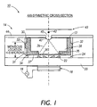
- FIGURE 1 is a cross-sectional view of an acoustic drop ejection unit 10, having a reagent cartridge 12 inserted within an acoustic drop ejection mechanism 14.
- a transducer 16 is supplied with energy by a power supply source 18.
- Transducer 16 is provided on a surface of substrate 20, such as glass.
- Patterned or located on an opposite surface of glass substrate 20 is a focusing lens configuration 22, such as a Fresnel lens. It is to be appreciated that other types of focusing configurations may also be used in place of Fresnel lens 22.
- a connecting layer 24, such as an acoustic coupling fluid is located between Fresnel lens 22 and reagent cartridge 12.
- the acoustic coupling fluid 24 is selected to have low acoustic attenuation.
- An example of an acoustic coupling fluid having beneficial acoustic characteristics for this application include water.
- connecting layer 24 may be provided as a thin layer of grease. The grease connection will be useful when the joining surfaces are relatively flat in order to minimize the possibility of trapped bubbles.
- a thin membrane 36 is formed on a lower surface 37 of cartridge 12, positioned substantially above Fresnel lens 22.
- Membrane 36 is an acoustically thin membrane, wherein acoustically thin is defined in this context to mean that the thickness of the membrane is small enough that it passes over 50% of its incident acoustic energy through to biofluid 38 within cartridge 12.
- transducer 16 In operation, energization of transducer 16 emits an acoustic wave which travels through glass substrate 20 to Fresnel lens 22.
- the lens produces a focused acoustic energy wave 39 that passes through acoustic coupling fluid 24 and membrane 36, reaching an apex at biofluid meniscus surface 40 of biofluid 38.
- Supplying of the focused energy to surface 40 causes disruptions in the surface resulting in ejection of a biofluid drop 42 from cartridge 12 to substrate 43, such as paper, glass, plastic or other appropriate material.
- the biofluid ejected can be as small as approximately 15um in diameter. However, this size limitation is based on the physical components used, and it is to be understood that drops ejected by an acoustic drop ejection unit can be made smaller or larger in accordance with design changes to the physical components.
- the surface from which biofluid drops 42 are ejected can be either totally open or contained by an aperture plate or lid 44.
- the lid 44 will have a suitably sized aperture 45, which is larger than the ejected drop size in order to avoid any interference with drop ejection.
- Aperture 45 must be sized so that the surface tension of meniscus 40 across aperture 45 sufficiently exceeds the gravitational force on biofluid 38. This design will prevent biofluid 38 from falling from regent cartridge 12 when cartridge 12 is turned with aperture 45 facing down.
- the aperture down configuration has a benefit of maintaining the biofluid 38 clean from material which may fall from substrate 43.
- transducer 16 Operation of transducer 16, power supply 18, glass substrate 20, and lens 22 function in a manner similar to previously discussed drop ejection units used in the field of acoustic ink printing. Such operation is well known in the art.
- Reagent cartridge 12 is separated from acoustic coupling fluid 24 by membrane 36.
- the entire cartridge may be injection molded from a biologically inert material, such as polyethylene or polypropylene.
- Cartridge 12 is operationally linked to the acoustic drop emitter mechanism 14 by a connection interface which includes membrane 36 and acoustic coupling fluid 24.
- the width of reagent cartridge 12 may be approximately 300 microns, and membrane 36 may be 3 microns thick.
- the meniscus location should be maintained within plus or minus five microns from an ideal surface level.
- Power supply source 18 is a controllably variable. By altering the output of power supply source 18, energy generated by transducer 16 is adjusted, which in turn may be used to alter the volume of an emitted biofluid drop 42.
- the location of the meniscus surface 40 must be maintained within tolerances defined by the device configuration. While in the previously discussed embodiment, due to the specific acoustic drop ejection mechanism being used, that tolerance is +/- 5 microns. It is to be appreciated other ranges exist for differently configured devices.
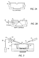
- FIGURE 2A shows reagent cartridge 12 when it is full of biofluid 38.
- FIGURE 2B the same cartridge 12 is shown in an empty state.
- empty in this embodiment refers to there being less biofluid 38 than the predetermined parameter height 46, in this instance 10 microns.
- the predetermined parameter height 46 in this instance 10 microns.
- biofluid drop ejection unit 10 For useful operation of biofluid drop ejection unit 10, it is desirable to provide a configuration which detects the biofluid level while the cartridge 12 is within acoustic drop mechanism 14.
- FIGURE 3 illustrated is a first embodiment of a biofluid level detection mechanism 50 which is capable of measuring the level of biofluid 38 within cartridge 12, when cartridge is within ejector mechanism 14.
- Biofluid level detection mechanism 50 includes a laser 52 positioned such that laser beam 54 emitted therefrom is reflected off of the upper surface 56 of biofluid 38.
- a laser detection configuration 58 includes a first laser beam detector 60 and a second laser beam detector 62.
- First laser beam detector 60 is positioned at an angle relative to the acoustic drop ejection unit 10 such that when cartridge 12 has biofluid within the predetermined parameters, the angle of reflected laser beam 64 will impinge upon sensor 60.
- Laser beam detector 62 is positioned at an angle relative to acoustic drop ejection unit 10 such that it will sense reflected laser beam 66 which is at an angle corresponding to the biofluid 38 being out of the acceptable range for proper operation.
- the outputs of sensor detector 60 and sensor detector 62 are provided to a controller 68.
- This information along with preprogrammed information as to location of the laser 52 and detectors 60, 62, is used to calculate the biofluid level.
- the information obtained by controller 68 may then be used in further control of the biofluid level, as will be discussed in greater detail below.
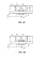
- controller 70 controls the output of power supply 72 to initiate a short pulse acoustic wave 76 to be transmitted from Fresnel lens 78 to the upper surface 80 of biofluid 38. Controller 70 controls the output from power supply 72 such that short pulse acoustic wave 76 is not sufficient to cause the emission or ejection of a biofluid drop. Rather, short pulse acoustic wave 76 is emitted, and sensed by lens 22. This outbound acoustic wave 76, as shown in FIGURE 4A reaches surface 80 and is then reflected back 84 towards lens 22, generating an rf signal provided to controller 70 with an indication of the emission and return of acoustic wave 76.
- the time taken for acoustic wave 76 to travel to surface 80 and back to lens 22 is used to determine whether the biofluid is at an appropriate level. This information will be used to adjust the fluid level, as will be discussed in further detail below. In an alternative embodiment, it is possible to vary the supplied frequency to shift the focus, in order to maintain the acoustic wave at the meniscus surface.
- Controller 70 is designed to determine the time from emission of the outbound acoustic wave 76 until receipt of the reflected wave 84 having been preprogrammed with parameters as to the speed of the acoustic wave, the depth of the biofluid in cartridge 12 when full, the viscosity of the biofluid as well as other required parameters. Using this information controller 70 calculates the biofluid level within cartridge 12. This information is then used in later level control designs which will be discussed in greater detail below.
- controller 70 may be designed to sense an amplitude of the returned wave.
- the sensed amplitude is correlated to the biofluid level.
- the returned signal of acoustic wave 76 will carry with it amplitude information. If the fluid height is not at an appropriate level, either too high or too low, the amplitude will be lower than expected.
- the returned amplitude will be at a peak when the fluid is at a correct level for ejector operation. Therefore, to determine the proper level the volume of biofluid is altered and a measurement is made to determine if the returned amplitude is closer or further from maximum amplitude. Dependent upon whether fluid was added or removed and the reaction of the amplitude, it can be determined whether more or less biofluid is needed.
- FIGURE 5 illustrated is a further embodiment of biofluid level detection in accordance with the present invention.
- Sound pulses emitted by lens 22 are supplied to controller 88.
- the controller 88 is configured to accumulate and count the pulses received, and to correlate that value to the known average volume of biofluid ejected in each drop. Controller 88 then inferentially calculates the level of biofluid 38 within cartridge 12. This biofluid level information is then used to control the biofluid level.
- FIGURE 6 illustrated is a first embodiment for altering the position of the reagent cartridge 12 located within the acoustic drop ejection mechanism 14.
- the position change is made in response to the detection of biofluid levels by techniques shown, for example, in connection with FIGURES 3, 4A, 4B or 5.
- auxiliary fluid chamber 90 placed in operational communication with chamber 30 via chamber connect 92.
- additional acoustic connection fluid 94 is supplied to chamber 30 by activation of plunger 96.
- Plunger 96 may be a high-precision plunger controlled by a computer-driven actuator 98.
- Computer-driven actuator 98 is provided with signals via any one of the controllers 68, 70 or 88 previously discussed in connection with FIGURES 3, 4A, 4B and 5.
- Plunger 96 is moved inward forcing supplementing acoustic connection fluid 94 into chamber 30 to raise reagent cartridge 12 to a sufficient amount to ensure that surface 80 is within the acceptable height range.
- FIGURE 7 is a side view of a two piece drop ejection unit 100 employing an alternative reagent cartridge 102 configuration.
- a main reservoir 106 is also provided to feed ejection reservoir 104.
- a connection path between the ejection reservoir 104 and main reservoir 106 is provided via reservoir connect 108.
- additional biofluid 38 is supplied via the main reservoir 106 and reservoir connect 108.
- Reagent cartridge 102 is in operational arrangement with acoustic drop ejection mechanism 110.
- Ejection reservoir 104 is located over lens 22, glass substrate 20, and transducer 16 in a manner which allows generated acoustic energy to be focused, and transferred to the ejection reservoir 104 with sufficient energy to emit biofluid drops.
- this two piece design connecting layer 24 such as an acoustic coupling fluid is provided, and a bottom portion of cartridge 102 is formed with membrane 112 which allows sufficient acoustic energy to be transferred to ejection reservoir 104.
- Main reservoir 106 is filled through filling port 114.
- the main reservoir 106 and reservoir connect 108 use capillary action to assist in an initial filling of the ejection reservoir 104 when it is in an empty state. Thereafter, as drops are ejected from ejection reservoir 104 surface tension causes biofluid from the main reservoir to be drawn into the ejection reservoir.
- aperture 45 of ejection reservoir 104 is sufficiently sized smaller than filling port 111 of main reservoir 106 and also small enough to overcome gravitational forces due to reservoir height, that biofluid in main reservoir 106 is drawn into the ejection reservoir 104.
- FIGURE 8 set forth is a single piece biofluid acoustic ejection unit 120. Distinctions between the two-piece biofluid drop ejection unit 10 and the single-piece unit 120, include that seal 32 of reagent cartridge 12 is no longer used. Rather, reagent cartridge 122 has side wall 124 with a planar external surface 126 in direct contact with walls 26,28 of mechanism 14. Therefore, a permanent connection is made between walls 26, 28 and reagent cartridge 122. Such connection may be made during the manufacture of the device via lithographic techniques and/or by use of known adhesion technology.
- lower surface 128, including membrane 130 may be removed allowing biofluid 38 to come into direct contact with lens 22. Still a further embodiment is to remove cartridge 112 and supply the biofluid directly into chamber 30, where chamber 30 acts as a non-contaminated biofluid containment area. Under this design chamber 30 is filled with biofluid in a contamination-free environment.
- FIGURE 9 shows an embodiment for supplying additional biofluid to reagent cartridge 140 in order to maintain the biofluid 38 at a desired level.
- auxiliary fluid holding area 142 has a bellows-shaped configuration with an interior 144 filled with biofluid 38.
- a level-sensing device e.g. FIGURES 3, 4A, 4B and 5
- a level-sensing device e.g. FIGURES 3, 4A, 4B and 5
- precision plunger 148 controlled by computer operated actuator 150, is moved inward compressing auxiliary biofluid holding chamber 142. This action forces a predetermined amount of biofluid 38 into main chamber 146 such that biofluid meniscus surface 152 is moved to an acceptable, usable level.
- FIGURE 10 depicts a second embodiment for supplying additional biofluid 38 to reagent chamber 160.
- collapsible auxiliary area or chamber 162 is in fluid communication with ejection reservoir 164.
- squeezing mechanism 166 is activated by a computer-controlled actuator 168 to provide inward force on collapsible chamber 162. Pressure is applied in a sufficient amount to resupply ejection reservoir 164 with biofluid, to an acceptable usable level.
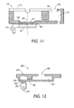
- FIGURE 11 illustrated is an alternative embodiment for a single piece acoustic drop ejection unit 170.
- ejection reservoir 172 and main reservoir 174 are placed in fluid communication by reservoir connect 176.
- Biofluid 38 is supplied from main reservoir 174 to ejection reservoir 172 due to surface tension at the meniscus, as discussed in connection with FIGURE 7.
- Transducer 16 is in operational connection to substrate 178 on a first surface 180, and lens 22 is on a second surface 182 whereby these components are formed as part of the single unit 170.
- connecting layer 24 of FIGURE 7 is not required due to the single component disposable nature of the present embodiment.
- biofluid comes into direct contact with lens 22. Therefore, there is no need for the acoustic coupling fluid provided in FIGURE 7.
- Main reservoir 174 is filled through filling port 183.
- FIGURE 12 is a side view of a single piece piezoelectric drop ejection unit 190.
- Ejection reservoir 192 is connected to main reservoir 194 via reservoir connect 196.
- Biofluid is supplied to main reservoir 194 via filling port 198.
- a piezo actuator 200 is in operational attachment to a lower surface 202 of ejection reservoir 192.
- An upper surface defining the ejection reservoir 192 has formed therein an ejection nozzle 204.
- piezo actuator 200 is actuated by power supply 210, which in combination with lower surface 202, define a unimorph, and deflects in response to an applied voltage.
- a force is imposed such that the unimorph configuration moves into ejection reservoir 192, thereby altering the volume of ejection reservoir 192, which in turn forces biofluid from the ejection reservoir 202 through nozzle 204 as an ejected biodrop.
- the size of nozzle 204 is a controlling factor as to the size of the ejected drops.
- main reservoir 194 has an internal dimension of 1 cm in length and 2.5 mm in height.
- the width of the overall piezoelectric drop ejection unit is 5 mm.
- the volume of biofluid in a full main reservoir may be from 50 to 150 microliters and the biofluid in the ejection reservoir may be between 5 and 25 microliters.
- the ratio of biofluid in the reservoirs may range from 2 to 1 up to 10 to 1. In other situations the ratio may be greater.
- the volume of biofluid drops may be in the picoliter range.
- lower surface 202 connected to piezo actuator 200 is integrated into the overall piezoelectric drop ejector unit 190. Under this construction, when biofluid of unit 190 is depleted, the entire unit 190 may be disposed.
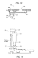
- FIGURE 13 illustrated is a side view of a two piece piezoelectric biofluid drop ejection unit 220 having a disposable portion and a reusable portion.
- the disposable portion includes a main reservoir 222 and an ejection reservoir 224 which has integrated therein an ejection nozzle 226.
- the ejection reservoir 226, being connected to main reservoir 222 via reservoir connect 230. Transmission of biofluid from main reservoir 222 to ejection reservoir 226, via reservoir connect 230 occurs due to surface tension existing in ejection reservoir 224.
- a filling port 232 is also included.
- the reusable portion of unit 220 includes piezo actuator 240 powered by a power supply source 234.
- the piezo actuator 240 is carried on a reusable frame 244.
- a lower surface of ejection reservoir 224 is formed as a membrane 246 and is connected to an upper surface or diaphragm 248 of reusable frame 244.
- Diaphragm 248 is bonded or otherwise connected to piezo actuator 240 such that diaphragm 248 acts as part of a unimorph structure to create a necessary volume change within ejection reservoir 226 in order to eject a biofluid drop from ejection nozzle 224.
- Membrane 246 of cartridge 222 acts to transfer the volume change in the reusable portion 244 into the disposable portion.
- the reusable portion has a flexible membrane with a piezo actuator on one surface to generate the volume displacement necessary to expel a biofluid drop.
- a container may be fabricated to place a connecting liquid in contact with the transducer/membrane. This liquid assists in transmitting the transducer-induced volume changes to a second membrane on a different container surface.
- the container edges are constructed to make a hermetic seal between the reusable and the disposable parts.
- the container has a provision for removing (bleeding) air bubbles from the connecting liquid.
- the opposite surface is open before assembling with the disposable part.
- a hermetic seal is provided between the disposable and reusable portions, and the reusable portion is filled with a connecting liquid to transmit the volume changes from the transducer to the disposable portion. To minimize compliance and absorption of volume changes, all air bubbles in this fluid are removed before operation by bleeding them through a bleeding mechanism in the reusable portion.
- piezo actuator configurations such as bulk or shear mode designs, may also be used in conjunction with the present invention.
- an adjustment of the generated acoustic wave is used to extend the operational capabilities of the system. This embodiment is applicable to both a Fresnel lens and a spherical lens.
- controller 70 supplies signal generator 12 with an indication to increase or decrease amplitude output when it is determined that the fluid height is not at the desired level. By this action, the focal point of the acoustic wave is adjusted to occur at the actual meniscus height.
- a further embodiment would be to again use the concepts of FIGURES 4A and 4B to detect that the fluid height is not at a desired level. Thereafter, when using a Fresnel lens, it is possible to change operational frequency in order to tune the focal point to the exact fluid height existing at a particular time within the device. For a Fresnel lens the focal position is substantially a linear function of frequency. Therefore, in FIGURES 4A and 4B, the initial step is measurement of the actual biofluid level. Then, controller 70 tunes the frequency of operation such that the focal point is moved to where the meniscus surface actually exists.
- the frequency and acoustic control concepts may be used alone, without the use of an actuator, or in connection with actuator concepts to provide a more refined control.
- initial operation may not produce desired drop output.
- air bubbles exist within the ejection reservoir, non-spherical drops, or drops which are not of a proper consistency or size may be ejected, and more likely no drops will be produced. Therefore, a priming of the ejection unit is desirable.
- FIGURE 14 illustrates a primer connection or mechanism 250 which may be used in accordance with the present invention.
- the primer connection 250 is located over a nozzle (204, 226) which is configured to emit biofluid from an ejection reservoir (192, 224).
- disposable primer connection 250 may be a robotically actuated device which moves over an ejection nozzle (204,226).
- the primer connection 250 includes a permanent vacuum nozzle 252 connected to a vacuum unit 254. Placed around permanent vacuum nozzle 252 is a disposable tubing or sleeve 256 made of an elastomaric or other suitable material.
- the vacuum nozzle 252 is moved downward, placing the disposable tubing 256 into a loose contact with nozzle (204, 226). Vacuuming action vacuums air out of the ejection reservoir (204,226).
- a robotically controlled fluid or liquid height detection sensor 258 determines when the biofluid has reached a level, such that air within the ejection reservoir has been removed. This priming operation permits for proper initial drop ejection operation. Once the detector 258 has sensed an appropriate priming level has been reached, the priming operation is ended by removal of the priming mechanism from operational attachment with the drop ejection unit.
- Robotically controlled primer connection 250 and liquid height detection sensor 258 may be controlled by a controller 259. Controller 259 generates actuation signals controlling movement of these robotically controlled elements. It is to be appreciated that detection sensor 258 may in fact be integrated as part of the primer connection 250. Movement of primer connection 250 and detection sensor 258 may be accomplished by one of many known configurations, and the mechanical components necessary for such movement are well known in the art.
- primer connection 250 and level detector 258 may themselves be stationary and it is the drop ejection unit which is moved appropriately underneath the primer connection 250. In either case, it is to be understood that primer connection 250 and level detector 258 represent a multiple number of such configurations to prime an array of drop ejector units in a single drop ejector head. Similarly, the embodiment which will be discussed in connection with FIGURE 15 is also representative of such an array of components.
- disposable tubing 256 may be replaced prior to a next priming operation.
- vacuum unit 254, controlled by controller 259 is capable of generating a controllable vacuum force which causes the vacuuming action previously described.
- controllable force By having the controllable force, adjustments dependent upon the viscosity of the biofluid can be taken into account. For example, a larger vacuum force may be applied for a biofluid with greater viscosity than a biofluid which is more liquid.
- vacuum nozzle 252 has been defined as permanent. By this discussion, permanent is intended to mean permanent compared to the disposable tubing 256.
- the connection between the vacuum unit 254 and vacuum nozzle 252 may have detachable characteristics.
- the vacuum nozzle may be attached by a snap-fit connection, a set screw or other connection technique which allows for removal of the nozzle.
- FIGURE 15 illustrated is a modified single piece piezoelectric drop ejection unit 260 designed in a manner similar to the ejection unit 190 illustrated in FIGURE 12. Therefore common elements are numbered similarly.
- the presently configured unit 260 also includes a priming reservoir 262 having a priming opening 264. Priming is accomplished by movement of priming system 250 to a position over priming opening 264. Once sleeve 256 is engaged with opening 264, a vacuum pressure is applied to draw the biofluid for priming purposes. During this operation, power supply 210 generates pulses for activation of piezo actuator 200 in order to move biofluid within ejection reservoir 192 up to nozzle 204.
Landscapes
- Health & Medical Sciences (AREA)
- Clinical Laboratory Science (AREA)
- Chemical & Material Sciences (AREA)
- Chemical Kinetics & Catalysis (AREA)
- Automatic Analysis And Handling Materials Therefor (AREA)
- Apparatus Associated With Microorganisms And Enzymes (AREA)
- Special Spraying Apparatus (AREA)
- Nozzles (AREA)
Applications Claiming Priority (2)
| Application Number | Priority Date | Filing Date | Title |
|---|---|---|---|
| US09/721,388 US6861034B1 (en) | 2000-11-22 | 2000-11-22 | Priming mechanisms for drop ejection devices |
| US721388 | 2000-11-22 |
Publications (3)
| Publication Number | Publication Date |
|---|---|
| EP1208914A2 true EP1208914A2 (de) | 2002-05-29 |
| EP1208914A3 EP1208914A3 (de) | 2003-10-15 |
| EP1208914B1 EP1208914B1 (de) | 2006-10-11 |
Family
ID=24897776
Family Applications (1)
| Application Number | Title | Priority Date | Filing Date |
|---|---|---|---|
| EP01126959A Expired - Lifetime EP1208914B1 (de) | 2000-11-22 | 2001-11-13 | Mechanismus zur Inbetriebnahme von Geräten zur Abgabe von Tropfen |
Country Status (4)
| Country | Link |
|---|---|
| US (1) | US6861034B1 (de) |
| EP (1) | EP1208914B1 (de) |
| JP (1) | JP3943907B2 (de) |
| DE (1) | DE60123735T2 (de) |
Cited By (6)
| Publication number | Priority date | Publication date | Assignee | Title |
|---|---|---|---|---|
| US6932097B2 (en) | 2002-06-18 | 2005-08-23 | Picoliter Inc. | Acoustic control of the composition and/or volume of fluid in a reservoir |
| US6938995B2 (en) | 2001-12-04 | 2005-09-06 | Picoliter Inc. | Acoustic assessment of fluids in a plurality of reservoirs |
| US7354141B2 (en) | 2001-12-04 | 2008-04-08 | Labcyte Inc. | Acoustic assessment of characteristics of a fluid relevant to acoustic ejection |
| US7454958B2 (en) | 2001-12-04 | 2008-11-25 | Labcyte Inc. | Acoustic determination of properties of reservoirs and of fluids contained therein |
| US7717544B2 (en) | 2004-10-01 | 2010-05-18 | Labcyte Inc. | Method for acoustically ejecting a droplet of fluid from a reservoir by an acoustic fluid ejection apparatus |
| US7900505B2 (en) | 2000-09-25 | 2011-03-08 | Labcyte Inc. | Acoustic assessment of fluids in a plurality of reservoirs |
Families Citing this family (14)
| Publication number | Priority date | Publication date | Assignee | Title |
|---|---|---|---|---|
| JP4606543B2 (ja) * | 2000-04-13 | 2011-01-05 | パナソニック株式会社 | 光学特性計測装置における被検溶液量確認方法および計測系制御方法 |
| US6749812B2 (en) * | 2000-06-26 | 2004-06-15 | Vistalab Technologies | Automatic pipette detipping |
| WO2002000346A2 (en) * | 2000-06-26 | 2002-01-03 | Vistalab Technologies, Inc. | Handheld pipette |
| US8122880B2 (en) * | 2000-12-18 | 2012-02-28 | Palo Alto Research Center Incorporated | Inhaler that uses focused acoustic waves to deliver a pharmaceutical product |
| US7121275B2 (en) * | 2000-12-18 | 2006-10-17 | Xerox Corporation | Method of using focused acoustic waves to deliver a pharmaceutical product |
| JP4095968B2 (ja) * | 2004-02-06 | 2008-06-04 | 株式会社日立ハイテクノロジーズ | 液体分注装置、それを用いた自動分析装置、及び液面検出装置 |
| US7946683B2 (en) * | 2007-07-20 | 2011-05-24 | Eastman Kodak Company | Printing system particle removal device and method |
| USD620602S1 (en) | 2008-01-03 | 2010-07-27 | Vistalab Technologies, Inc. | Pipette |
| US8333451B2 (en) * | 2010-08-12 | 2012-12-18 | Cordis Corporation | Sub-threshold voltage priming of inkjet devices to minimize first drop dissimilarity in drop on demand mode |
| WO2012032503A1 (en) * | 2010-09-07 | 2012-03-15 | University Of Limerick | A liquid droplet dispenser |
| WO2014057480A2 (en) * | 2012-10-12 | 2014-04-17 | Koninklijke Philips N.V. | Optical fill detection |
| EP3426408A4 (de) | 2016-07-27 | 2019-04-24 | Hewlett-Packard Development Company, L.P. | Vibrieren eines dosierkopfes zum bewegen von flüssigkeit |
| US10743109B1 (en) * | 2020-03-10 | 2020-08-11 | Recursion Pharmaceuticals, Inc. | Ordered picklist for liquid transfer |
| DE102020115515A1 (de) | 2020-06-10 | 2021-12-16 | Hamilton Bonaduz Ag | Pipettiervorrichtung mit durch Gasschall ausgelöster Dispensation von Flüssigkeitsmengen im Bereich von vorzugsweise 10 bis 500 nl |
Family Cites Families (68)
| Publication number | Priority date | Publication date | Assignee | Title |
|---|---|---|---|---|
| CA1082283A (en) | 1976-01-15 | 1980-07-22 | Kenneth H. Fischbeck | Separable liquid droplet instrument and piezoelectric drivers therefor |
| US4399711A (en) * | 1980-04-18 | 1983-08-23 | Beckman Instruments, Inc. | Method and apparatus ensuring full volume pickup in an automated pipette |
| JPS58194564A (ja) | 1982-05-11 | 1983-11-12 | Canon Inc | インクジェット装置 |
| US4633274A (en) | 1984-03-30 | 1986-12-30 | Canon Kabushiki Kaisha | Liquid ejection recording apparatus |
| US4797693A (en) | 1987-06-02 | 1989-01-10 | Xerox Corporation | Polychromatic acoustic ink printing |
| US5429952A (en) | 1988-02-02 | 1995-07-04 | Biocode, Inc. | Marking of products to establish identity and source |
| JPH087222B2 (ja) * | 1990-01-18 | 1996-01-29 | 持田製薬株式会社 | 自動分注希釈装置 |
| DE4024545A1 (de) | 1990-08-02 | 1992-02-06 | Boehringer Mannheim Gmbh | Verfahren und vorrichtung zum dosierten zufuehren einer biochemischen analysefluessigkeit auf ein target |
| US5229793A (en) | 1990-12-26 | 1993-07-20 | Xerox Corporation | Liquid surface control with an applied pressure signal in acoustic ink printing |
| US5163582A (en) * | 1991-04-30 | 1992-11-17 | Andronic Devices Ltd. | Apparatus and method for aliquotting blood serum or blood plasma |
| US5250962A (en) | 1991-10-16 | 1993-10-05 | Xerox Corporation | Movable ink jet priming station |
| JP3317308B2 (ja) | 1992-08-26 | 2002-08-26 | セイコーエプソン株式会社 | 積層型インクジェット記録ヘッド、及びその製造方法 |
| JP3144948B2 (ja) | 1992-05-27 | 2001-03-12 | 日本碍子株式会社 | インクジェットプリントヘッド |
| JP3144949B2 (ja) | 1992-05-27 | 2001-03-12 | 日本碍子株式会社 | 圧電/電歪アクチュエータ |
| WO1993025914A1 (en) | 1992-06-08 | 1993-12-23 | Behring Diagnostics, Inc. | Liquid dispensing system |
| FI922939A0 (fi) * | 1992-06-24 | 1992-06-24 | Labsystems Oy | Knappipett. |
| EP0608879B1 (de) * | 1993-01-29 | 1999-10-27 | Canon Kabushiki Kaisha | Tintenstrahlgerät |
| US5450105A (en) | 1993-04-30 | 1995-09-12 | Hewlett-Packard Company | Manual pen selection for clearing nozzles without removal from pen carriage |
| US5796417A (en) | 1993-10-29 | 1998-08-18 | Hewlett-Packard Company | Compliant interconnect assembly for mounting removable print cartridges in a carriage |
| US5684518A (en) | 1993-10-29 | 1997-11-04 | Hewlett-Packard Company | Interconnect scheme for mounting differently configured printheads on the same carriage |
| US5565113A (en) | 1994-05-18 | 1996-10-15 | Xerox Corporation | Lithographically defined ejection units |
| DE4423878A1 (de) * | 1994-07-07 | 1996-01-11 | Boehringer Mannheim Gmbh | Vorrichtung und Verfahren zum Abscheiden von magnetischen Mikropartikeln |
| JPH0894628A (ja) * | 1994-09-28 | 1996-04-12 | Lion Corp | 分析用容器前処理装置 |
| US5631678A (en) | 1994-12-05 | 1997-05-20 | Xerox Corporation | Acoustic printheads with optical alignment |
| US5912679A (en) * | 1995-02-21 | 1999-06-15 | Kabushiki Kaisha Toshiba | Ink-jet printer using RF tone burst drive signal |
| JPH08254446A (ja) | 1995-03-16 | 1996-10-01 | Fujitsu Ltd | 超音波印字方法,超音波印字装置及び音響レンズの成形方法 |
| US5895631A (en) * | 1995-03-20 | 1999-04-20 | Precision System Science Co., Ltd. | Liquid processing method making use of pipette device and apparatus for same |
| JPH08338849A (ja) * | 1995-04-11 | 1996-12-24 | Precision Syst Sci Kk | 液体の吸引判別方法およびこの方法により駆動制御される分注装置 |
| US6158269A (en) * | 1995-07-13 | 2000-12-12 | Bayer Corporation | Method and apparatus for aspirating and dispensing sample fluids |
| US5811306A (en) * | 1995-09-04 | 1998-09-22 | Fuji Photo Film Co., Ltd. | Liquid spotting method |
| US5658802A (en) | 1995-09-07 | 1997-08-19 | Microfab Technologies, Inc. | Method and apparatus for making miniaturized diagnostic arrays |
| US5665601A (en) * | 1996-01-22 | 1997-09-09 | Johnson & Johnson Clinical Diagnostics, Inc. | Avoiding bubble formation while sensing air-liquid interface using pressurized air flow |
| US6114122A (en) | 1996-03-26 | 2000-09-05 | Affymetrix, Inc. | Fluidics station with a mounting system and method of using |
| US5958342A (en) | 1996-05-17 | 1999-09-28 | Incyte Pharmaceuticals, Inc. | Jet droplet device |
| US5807523A (en) * | 1996-07-03 | 1998-09-15 | Beckman Instruments, Inc. | Automatic chemistry analyzer |
| US5945070A (en) * | 1996-10-31 | 1999-08-31 | Merck & Co., Inc. | Reaction vessel filter for combinatorial chemistry or biological use |
| US5877580A (en) | 1996-12-23 | 1999-03-02 | Regents Of The University Of California | Micromachined chemical jet dispenser |
| US5744096A (en) * | 1997-02-21 | 1998-04-28 | Cholestech Corporation | Automated immunoassay cassette |
| EP0865824B1 (de) | 1997-03-20 | 2004-05-19 | F. Hoffmann-La Roche Ag | Mikromechanische Pipettiervorrichtung |
| DE69823904T2 (de) | 1997-03-20 | 2005-06-16 | F. Hoffmann-La Roche Ag | Mikromechanische Pipettiervorrichtung |
| WO1998041531A2 (en) | 1997-03-20 | 1998-09-24 | University Of Washington | Solvent for biopolymer synthesis, solvent microdroplets and methods of use |
| JPH10286974A (ja) | 1997-04-14 | 1998-10-27 | Brother Ind Ltd | インクジェットプリンタ |
| US5935523A (en) * | 1997-05-29 | 1999-08-10 | Medical Laboratory Automation, Inc. | Apparatus for accessing a sealed container |
| WO1999001576A1 (en) | 1997-07-02 | 1999-01-14 | University Of Bristol | Method of determining the genotype of an organism using an allele specific oligonucleotide probe which hybridises to microsatellite flanking sequences |
| US5943075A (en) | 1997-08-07 | 1999-08-24 | The Board Of Trustees Of The Leland Stanford Junior University | Universal fluid droplet ejector |
| JP3577917B2 (ja) * | 1997-10-31 | 2004-10-20 | 株式会社日立製作所 | 自動分析装置 |
| DE19754000A1 (de) | 1997-12-05 | 1999-06-17 | Max Planck Gesellschaft | Vorrichtung und Verfahren zur elektrisch ausgelösten Mikrotropfenabgabe mit einem Dispensierkopf |
| US6060320A (en) * | 1997-12-05 | 2000-05-09 | Bayer Corporation | Method of verifying aspirated volume in automatic diagnostic system |
| US6063339A (en) * | 1998-01-09 | 2000-05-16 | Cartesian Technologies, Inc. | Method and apparatus for high-speed dot array dispensing |
| US6241947B1 (en) * | 1998-01-27 | 2001-06-05 | Fuji Photo Film Co., Ltd. | Chemical analysis system and blood filtering unit |
| US6235534B1 (en) * | 1998-04-27 | 2001-05-22 | Ronald Frederich Brookes | Incremental absorbance scanning of liquid in dispensing tips |
| US6165417A (en) | 1998-10-26 | 2000-12-26 | The Regents Of The University Of California | Integrated titer plate-injector head for microdrop array preparation, storage and transfer |
| IL127484A (en) | 1998-12-09 | 2001-06-14 | Aprion Digital Ltd | Laser container printing method and method |
| US6245518B1 (en) | 1998-12-11 | 2001-06-12 | Hyseq, Inc. | Polynucleotide arrays and methods of making and using the same |
| EP1141415A1 (de) | 1998-12-23 | 2001-10-10 | Rosetta Inpharmatics Inc. | Verfahren zur grobunterscheidung von profilen |
| US6242266B1 (en) | 1999-04-30 | 2001-06-05 | Agilent Technologies Inc. | Preparation of biopolymer arrays |
| ATE401125T1 (de) * | 1999-05-28 | 2008-08-15 | Bio Data Corp | Verfahren und vorrichtung zur direkten probenahme eines fluids für die mikrofiltration |
| US6322752B1 (en) * | 1999-09-08 | 2001-11-27 | Coulter International Corp. | Method and apparatus for aspirating and dispensing liquids |
| JP2001186880A (ja) | 1999-10-22 | 2001-07-10 | Ngk Insulators Ltd | Dnaチップの製造方法 |
| JP2001186881A (ja) | 1999-10-22 | 2001-07-10 | Ngk Insulators Ltd | Dnaチップの製造方法 |
| ATE358277T1 (de) | 1999-10-22 | 2007-04-15 | Ngk Insulators Ltd | Dna-chip und verfahren zur herstellung desselben |
| US6656432B1 (en) | 1999-10-22 | 2003-12-02 | Ngk Insulators, Ltd. | Micropipette and dividedly injectable apparatus |
| US6428750B1 (en) * | 2000-02-17 | 2002-08-06 | Rainin Instrument, Llc | Volume adjustable manual pipette with quick set volume adjustment |
| US6447723B1 (en) * | 2000-03-13 | 2002-09-10 | Packard Instrument Company, Inc. | Microarray spotting instruments incorporating sensors and methods of using sensors for improving performance of microarray spotting instruments |
| US20030048341A1 (en) | 2000-09-25 | 2003-03-13 | Mutz Mitchell W. | High-throughput biomolecular crystallization and biomolecular crystal screening |
| US6503454B1 (en) | 2000-11-22 | 2003-01-07 | Xerox Corporation | Multi-ejector system for ejecting biofluids |
| US6596239B2 (en) * | 2000-12-12 | 2003-07-22 | Edc Biosystems, Inc. | Acoustically mediated fluid transfer methods and uses thereof |
| US6869551B2 (en) | 2001-03-30 | 2005-03-22 | Picoliter Inc. | Precipitation of solid particles from droplets formed using focused acoustic energy |
-
2000
- 2000-11-22 US US09/721,388 patent/US6861034B1/en not_active Expired - Lifetime
-
2001
- 2001-11-13 EP EP01126959A patent/EP1208914B1/de not_active Expired - Lifetime
- 2001-11-13 DE DE60123735T patent/DE60123735T2/de not_active Expired - Lifetime
- 2001-11-15 JP JP2001350622A patent/JP3943907B2/ja not_active Expired - Fee Related
Cited By (8)
| Publication number | Priority date | Publication date | Assignee | Title |
|---|---|---|---|---|
| US7900505B2 (en) | 2000-09-25 | 2011-03-08 | Labcyte Inc. | Acoustic assessment of fluids in a plurality of reservoirs |
| US6938995B2 (en) | 2001-12-04 | 2005-09-06 | Picoliter Inc. | Acoustic assessment of fluids in a plurality of reservoirs |
| US7354141B2 (en) | 2001-12-04 | 2008-04-08 | Labcyte Inc. | Acoustic assessment of characteristics of a fluid relevant to acoustic ejection |
| US7454958B2 (en) | 2001-12-04 | 2008-11-25 | Labcyte Inc. | Acoustic determination of properties of reservoirs and of fluids contained therein |
| US7899645B2 (en) | 2001-12-04 | 2011-03-01 | Labcyte Inc. | Acoustic assessment of characteristics of a fluid relevant to acoustic ejection |
| US6932097B2 (en) | 2002-06-18 | 2005-08-23 | Picoliter Inc. | Acoustic control of the composition and/or volume of fluid in a reservoir |
| US7717544B2 (en) | 2004-10-01 | 2010-05-18 | Labcyte Inc. | Method for acoustically ejecting a droplet of fluid from a reservoir by an acoustic fluid ejection apparatus |
| US9221250B2 (en) | 2004-10-01 | 2015-12-29 | Labcyte Inc. | Acoustically ejecting a droplet of fluid from a reservoir by an acoustic fluid ejection apparatus |
Also Published As
| Publication number | Publication date |
|---|---|
| JP3943907B2 (ja) | 2007-07-11 |
| DE60123735T2 (de) | 2007-01-18 |
| EP1208914B1 (de) | 2006-10-11 |
| US6861034B1 (en) | 2005-03-01 |
| EP1208914A3 (de) | 2003-10-15 |
| JP2002210390A (ja) | 2002-07-30 |
| DE60123735D1 (de) | 2006-11-23 |
Similar Documents
| Publication | Publication Date | Title |
|---|---|---|
| US6623700B1 (en) | Level sense and control system for biofluid drop ejection devices | |
| EP1208914B1 (de) | Mechanismus zur Inbetriebnahme von Geräten zur Abgabe von Tropfen | |
| US6503454B1 (en) | Multi-ejector system for ejecting biofluids | |
| US6416294B1 (en) | Microdosing device | |
| EP2613889B1 (de) | Flüssigkeitstropfenspender | |
| US6713022B1 (en) | Devices for biofluid drop ejection | |
| US6280148B1 (en) | Microdosing device and method for operating same | |
| US7900850B2 (en) | Microdosing apparatus and method for dosed dispensing of liquids | |
| JP7803039B2 (ja) | 液滴吐出方法、組織体入り容器の製造方法及び液滴吐出装置 | |
| JP4241841B2 (ja) | 液体噴射装置のメンテナンス方法、及び液体噴射装置 | |
| EP1208912B1 (de) | Mehrfachejektorsystemprüfverfahren und -konfigurationen | |
| JPH08219956A (ja) | ピペット及びその使用方法 | |
| US6406130B1 (en) | Fluid ejection systems and methods with secondary dielectric fluid | |
| JP2003149093A (ja) | 液体分注装置および液体分注方法 | |
| US20060176341A1 (en) | Device for dispensing drops of a liquid | |
| JP2009137125A (ja) | 液体噴射装置のメンテナンス方法、及び液体噴射装置 |
Legal Events
| Date | Code | Title | Description |
|---|---|---|---|
| PUAI | Public reference made under article 153(3) epc to a published international application that has entered the european phase |
Free format text: ORIGINAL CODE: 0009012 |
|
| AK | Designated contracting states |
Kind code of ref document: A2 Designated state(s): AT BE CH CY DE DK ES FI FR GB GR IE IT LI LU MC NL PT SE TR |
|
| AX | Request for extension of the european patent |
Free format text: AL;LT;LV;MK;RO;SI |
|
| PUAL | Search report despatched |
Free format text: ORIGINAL CODE: 0009013 |
|
| AK | Designated contracting states |
Kind code of ref document: A3 Designated state(s): AT BE CH CY DE DK ES FI FR GB GR IE IT LI LU MC NL PT SE TR |
|
| AX | Request for extension of the european patent |
Extension state: AL LT LV MK RO SI |
|
| 17P | Request for examination filed |
Effective date: 20040415 |
|
| AKX | Designation fees paid |
Designated state(s): CH DE FR GB LI |
|
| 17Q | First examination report despatched |
Effective date: 20050615 |
|
| GRAP | Despatch of communication of intention to grant a patent |
Free format text: ORIGINAL CODE: EPIDOSNIGR1 |
|
| GRAS | Grant fee paid |
Free format text: ORIGINAL CODE: EPIDOSNIGR3 |
|
| GRAA | (expected) grant |
Free format text: ORIGINAL CODE: 0009210 |
|
| AK | Designated contracting states |
Kind code of ref document: B1 Designated state(s): CH DE FR GB LI |
|
| REG | Reference to a national code |
Ref country code: GB Ref legal event code: FG4D |
|
| REG | Reference to a national code |
Ref country code: CH Ref legal event code: EP Ref country code: CH Ref legal event code: NV Representative=s name: E. BLUM & CO. PATENTANWAELTE |
|
| REF | Corresponds to: |
Ref document number: 60123735 Country of ref document: DE Date of ref document: 20061123 Kind code of ref document: P |
|
| ET | Fr: translation filed | ||
| PLBE | No opposition filed within time limit |
Free format text: ORIGINAL CODE: 0009261 |
|
| STAA | Information on the status of an ep patent application or granted ep patent |
Free format text: STATUS: NO OPPOSITION FILED WITHIN TIME LIMIT |
|
| 26N | No opposition filed |
Effective date: 20070712 |
|
| REG | Reference to a national code |
Ref country code: CH Ref legal event code: PFA Owner name: XEROX CORPORATION Free format text: XEROX CORPORATION#XEROX SQUARE - 20A, 100 CLINTON AVENUE SOUTH#ROCHESTER, NEW YORK 14644 (US) -TRANSFER TO- XEROX CORPORATION#XEROX SQUARE - 20A, 100 CLINTON AVENUE SOUTH#ROCHESTER, NEW YORK 14644 (US) |
|
| PGFP | Annual fee paid to national office [announced via postgrant information from national office to epo] |
Ref country code: DE Payment date: 20101110 Year of fee payment: 10 |
|
| PGFP | Annual fee paid to national office [announced via postgrant information from national office to epo] |
Ref country code: GB Payment date: 20101110 Year of fee payment: 10 |
|
| PGFP | Annual fee paid to national office [announced via postgrant information from national office to epo] |
Ref country code: CH Payment date: 20111114 Year of fee payment: 11 Ref country code: FR Payment date: 20111118 Year of fee payment: 11 |
|
| REG | Reference to a national code |
Ref country code: CH Ref legal event code: PL |
|
| GBPC | Gb: european patent ceased through non-payment of renewal fee |
Effective date: 20121113 |
|
| PG25 | Lapsed in a contracting state [announced via postgrant information from national office to epo] |
Ref country code: LI Free format text: LAPSE BECAUSE OF NON-PAYMENT OF DUE FEES Effective date: 20121130 Ref country code: CH Free format text: LAPSE BECAUSE OF NON-PAYMENT OF DUE FEES Effective date: 20121130 |
|
| REG | Reference to a national code |
Ref country code: FR Ref legal event code: ST Effective date: 20130731 |
|
| REG | Reference to a national code |
Ref country code: DE Ref legal event code: R119 Ref document number: 60123735 Country of ref document: DE Effective date: 20130601 |
|
| PG25 | Lapsed in a contracting state [announced via postgrant information from national office to epo] |
Ref country code: DE Free format text: LAPSE BECAUSE OF NON-PAYMENT OF DUE FEES Effective date: 20130601 |
|
| PG25 | Lapsed in a contracting state [announced via postgrant information from national office to epo] |
Ref country code: GB Free format text: LAPSE BECAUSE OF NON-PAYMENT OF DUE FEES Effective date: 20121113 Ref country code: FR Free format text: LAPSE BECAUSE OF NON-PAYMENT OF DUE FEES Effective date: 20121130 |