EP1208926A2 - Vorrichtung zur Innenhochdruck-Umformung von Hohlkörpern - Google Patents
Vorrichtung zur Innenhochdruck-Umformung von Hohlkörpern Download PDFInfo
- Publication number
- EP1208926A2 EP1208926A2 EP01124188A EP01124188A EP1208926A2 EP 1208926 A2 EP1208926 A2 EP 1208926A2 EP 01124188 A EP01124188 A EP 01124188A EP 01124188 A EP01124188 A EP 01124188A EP 1208926 A2 EP1208926 A2 EP 1208926A2
- Authority
- EP
- European Patent Office
- Prior art keywords
- sealing
- stamp
- tool
- insertion piece
- stop
- Prior art date
- Legal status (The legal status is an assumption and is not a legal conclusion. Google has not performed a legal analysis and makes no representation as to the accuracy of the status listed.)
- Granted
Links
Images

Classifications
-
- B—PERFORMING OPERATIONS; TRANSPORTING
- B21—MECHANICAL METAL-WORKING WITHOUT ESSENTIALLY REMOVING MATERIAL; PUNCHING METAL
- B21J—FORGING; HAMMERING; PRESSING METAL; RIVETING; FORGE FURNACES
- B21J5/00—Methods for forging, hammering, or pressing; Special equipment or accessories therefor
-
- B—PERFORMING OPERATIONS; TRANSPORTING
- B21—MECHANICAL METAL-WORKING WITHOUT ESSENTIALLY REMOVING MATERIAL; PUNCHING METAL
- B21D—WORKING OR PROCESSING OF SHEET METAL OR METAL TUBES, RODS OR PROFILES WITHOUT ESSENTIALLY REMOVING MATERIAL; PUNCHING METAL
- B21D26/00—Shaping without cutting otherwise than using rigid devices or tools or yieldable or resilient pads, i.e. applying fluid pressure or magnetic forces
- B21D26/02—Shaping without cutting otherwise than using rigid devices or tools or yieldable or resilient pads, i.e. applying fluid pressure or magnetic forces by applying fluid pressure
- B21D26/033—Deforming tubular bodies
- B21D26/045—Closing or sealing means
-
- Y—GENERAL TAGGING OF NEW TECHNOLOGICAL DEVELOPMENTS; GENERAL TAGGING OF CROSS-SECTIONAL TECHNOLOGIES SPANNING OVER SEVERAL SECTIONS OF THE IPC; TECHNICAL SUBJECTS COVERED BY FORMER USPC CROSS-REFERENCE ART COLLECTIONS [XRACs] AND DIGESTS
- Y10—TECHNICAL SUBJECTS COVERED BY FORMER USPC
- Y10T—TECHNICAL SUBJECTS COVERED BY FORMER US CLASSIFICATION
- Y10T29/00—Metal working
- Y10T29/49—Method of mechanical manufacture
- Y10T29/49428—Gas and water specific plumbing component making
- Y10T29/49444—Elbow or L-shaped fitting making
Definitions
- the invention relates to a device for hydroforming hollow bodies, comprising an at least two-part tool and this on both Axial cylinders assigned to the sides, which seal the ends of the in the Close the contour space of the inserted hollow body, at least a sealing plunger a high pressure bore connected to a pressure medium source having.
- the pipe section After closing the ends of the Pipe section through the sealing stamp, the pipe section is made with the help of a suitable Pressurized with high internal pressure and at the same time Axial pressure (through the seals) on the pipe wall reshaped.
- the axial pressure and the internal pressure cause the pipe section to the inner contour or the final shape of the hollow body - creates the wall of the contour space of the forming tool.
- For hydroforming the material is brought into the plastic state, which during of the entire forming process taking into account material hardening and any tool forces are maintained.
- the invention is therefore based on the object in a device of the beginning to allow a more variable operating mode of the axial cylinder, in particular to improve the design of the sealing stamp.
- this object is achieved in an incredibly simple manner by that the sealing stamp is provided with a sealing head that can be detached from the front. This can be achieved in the event of wear or a program change more the entire sealing stamp, but only the one with a high-pressure cheese head screw attached sealing head needs to be replaced. This can be done from the full tool condition without mounting on the axial cylinder itself and thus happen very quickly, because after withdrawing the The releasable sealing head is freely accessible from the front, and this regardless of the particular design of the tool.
- a preferred embodiment of the invention provides that the sealing head at least is in two parts and from a leading arranged, with an inlet slope trained insertion piece and a subsequent guide receptacle consists.
- the invention is between the insertion piece and the A guide stop arranged. These components form a suitable screw connection a coherent unit.
- the stop provides a sealing edge in a development of the invention, on the stop creates the front edge of the workpiece to be formed the wearing part of the multi-part sealing head assembly, and only this wearing part needs to be replaced.
- a single and also much smaller wear part will continue to be also achieved when the insertion piece is advantageously formed with a sealing edge is.
- the specific location or the location of the course of the sealing edge on the insertion piece can be made dependent on the optimization of the centering.
- the insertion piece and the Stop hardened and the guide holder made of a material with good Toughness properties and high wear resistance exist.
- These deliberately different Material properties serve to increase the service life under Consideration of the stresses occurring on the individual components.
- bronze or a bronze alloy e.g. Gz-CuAlBzNi or AMPCO 25 or others comparable to it suitable materials. This offers good sliding properties of the sealing stamp or head in the upstream of the workpiece to be formed Tool inlet channel.
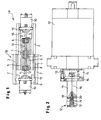
- FIG. 1 From a well known hydroforming (IHU) machine are left in Fig. 1 for the sake of simplicity in a drawing
- the tool 1a or 1b each has a clamping edge 2 provided upper and lower base plates 3 and 4.
- an upper and a lower base block 5 and 6 are the contour inserts 7 and end-side inlet channels 8 arranged.
- upstream consoles 9 On the inlet channels 8 upstream consoles 9 are Axial cylinder 10 attached, with a seal extension or Sealing plunger 11 arranged sealing plunger heads 12 are equipped, which are applied when it is loaded the axial cylinder 10 into a for forming in the tool cavity 13 inserted, to be formed hollow body-shaped workpiece 14 (see FIG. 5) in immerse the inlet channels 8 of the tool 1 in a sliding manner and from both ends seal it here.
- the axial cylinders 10 have the the Tool base blocks 5 or 6 facing ends an adapter 15 with it screwed on clamping ring 16 for receiving and holding the sealing stamp extension 11 on.
- This sealing stamp is accessible from the front High-pressure cheese head screw 17 a multi-part sealing head or sealing stamp head 12, 112 and 212 (see FIGS. 3 and 5) screwed on.
- the sealing head or sealing punch 12 engages with one of the anti-rotation devices serving paragraph 18 in the sealing plunger extension 11.
- High-pressure bore 19 extends through the sealing plunger extension 11 and the high-pressure cheese head screw 17 and thus opens in the operating position in the interior of the workpiece to be formed.
- Both between the adapter 15 and the clamping ring 16 as well as in the transition from the sealing stamp extension 11 to the sealing head or sealing stamp 12 (or 112 and 212) are sealing rings 20 arranged.
- FIG. 3 and 4 show an embodiment of a multi-part sealing head 112. This consists of one - in the order of the axial direction of movement Arrow 21 seen from the front when the axial cylinder 10 is acted upon - insertion piece 22, a stop 23 and a guide receptacle 24 together. These components 22, 23 and 24 are integrated into one unit by two cheese head screws 25 connected with each other.
- the insertion piece 22 has an entry slope 26 and an adjoining leading edge that tapers towards the stop 23 27 trained.
- the stop 23 is provided with a sealing edge 28 which in situ, i.e. when inserted into the open end of the hollow body to be formed Stamp seals the interior of the hollow body. In the lower one Half of FIG.
- the outer jacket 30 of the guide receptacle 24 lies when advancing the sealing punch arrangement of the inner wall of the inlet channel 8 (see. FIGS. 1 and 5) and ensures the leadership of the Sealing temple; there is no need for a separate guide unit become.
- the operating position is shown for the sealing stamp, in which the Sealing head 212 so far into the interior of the workpiece or hollow body 14 has penetrated that the sealing edge 28 of the stop 23 the inner cavity has applied sealingly to the end face of the workpiece 14. It is there further to see that the outer jacket 30 of the guide receptacle 24 in Interaction with the inlet channel 8 takes over the leadership of the sealing head 212 and the sealing punch extension 11 arranged in a guide bush 31 is.
- Pressure medium shortening length of the workpiece 14 becomes the sealing stamp arrangement advanced in the direction of arrow 21.
Landscapes
- Engineering & Computer Science (AREA)
- Mechanical Engineering (AREA)
- Physics & Mathematics (AREA)
- Fluid Mechanics (AREA)
- Shaping Metal By Deep-Drawing, Or The Like (AREA)
- Actuator (AREA)
- Perforating, Stamping-Out Or Severing By Means Other Than Cutting (AREA)
- Separation Using Semi-Permeable Membranes (AREA)
Abstract
Description
- Fig. 1
- ein Systembild eines IHU-Werkzeuges mit in den beiden Symmetriehälften dargestellten, voneinander verschiedenen Bauweisen;
- Fig. 2
- als Einzelheit in vergrößerter Darstellung einen Axialzylinder mit Dichtstempel;
- Fig. 3
- im Längsschnitt eine Ausführung eines mehrteiligen Dichtkopfes;
- Fig. 4
- den Dichtkopf nach Fig. 3 von rechts gesehen; und
- Fig. 5
- als Teilansicht eine andere Ausführung eines Dichtkopfes, mit seiner Führungsaufnahme im Einlaufkanal des Werkzeugs aufliegend und in ein umzuformendes Werkstück eingreifend gezeigt.
Claims (6)
- Vorrichtung zur Innenhochdruck-Umformung von Hohlkörpern, umfassend ein mindestens zweiteiliges Werkzeug und diesem an beiden Seiten zugeordnete Axialzylinder, die mit Dichtstempeln die Enden des in den Konturraum des Werkzeugs eingelegten Hohlkörpers verschließen, wobei zumindest ein Dichtstempel eine an eine Druckmittelquelle angeschlossene Hochdruckbohrung aufweist,
dadurch gekennzeichnet, daß der Dichtstempel (11) mit einem von vorne lösbaren Dichtkopf (12; 112;212) versehen ist. - Vorrichtung nach Anspruch 1,
dadurch gekennzeichnet, daß der Dichtkopf (112; 212) mindestens zweiteilig ist und aus einem voreilend angeordneten, mit einer Einlaufschräge (26) ausgebildeten Einführstück (22) sowie einer sich anschließenden Führungsaufnahme (24) besteht. - Vorrichtung nach Anspruch 2,
gekennzeichnet durch
einen zwischen dem Einführstück (22) und der Führungsaufnahme (24) angeordneten Anschlag (23). - Vorrichtung nach Anspruch 3,
dadurch gekennzeichnet, daß der Anschlag (23) eine Dichtkante (28) bereitstellt. - Vorrichtung nach Anspruch 2,
dadurch gekennzeichnet, daß das Einführstück (22) mit einer Dichtkante (29) ausgebildet ist. - Vorrichtung nach einem der Ansprüche 3 bis 5,
dadurch gekennzeichnet, daß das Einführstück (22) und der Anschlag (23) gehärtet sind und die Führungsaufnahme (24) aus einem Material mit guten Zähigkeitseigenschaften und hoher Verschleißfestigkeit besteht.
Applications Claiming Priority (2)
| Application Number | Priority Date | Filing Date | Title |
|---|---|---|---|
| DE10056610A DE10056610A1 (de) | 2000-11-15 | 2000-11-15 | Vorrichtung zur Innenhochdruck-Umformung von Hohlkörpern |
| DE10056610 | 2000-11-15 |
Publications (3)
| Publication Number | Publication Date |
|---|---|
| EP1208926A2 true EP1208926A2 (de) | 2002-05-29 |
| EP1208926A3 EP1208926A3 (de) | 2003-07-09 |
| EP1208926B1 EP1208926B1 (de) | 2004-12-08 |
Family
ID=7663396
Family Applications (1)
| Application Number | Title | Priority Date | Filing Date |
|---|---|---|---|
| EP01124188A Expired - Lifetime EP1208926B1 (de) | 2000-11-15 | 2001-10-11 | Vorrichtung zur Innenhochdruck-Umformung von Hohlkörpern |
Country Status (7)
| Country | Link |
|---|---|
| US (1) | US6591650B2 (de) |
| EP (1) | EP1208926B1 (de) |
| JP (1) | JP2002205126A (de) |
| KR (1) | KR20020038493A (de) |
| AT (1) | ATE284281T1 (de) |
| DE (2) | DE10056610A1 (de) |
| ES (1) | ES2233548T3 (de) |
Cited By (2)
| Publication number | Priority date | Publication date | Assignee | Title |
|---|---|---|---|---|
| CN102527812A (zh) * | 2011-12-26 | 2012-07-04 | 北京航空航天大学 | 一种管材自由胀形组合模具 |
| CN104596858A (zh) * | 2013-10-30 | 2015-05-06 | 上海汇众汽车制造有限公司 | 获取管材液压胀形基础性能参数的实验装置 |
Families Citing this family (10)
| Publication number | Priority date | Publication date | Assignee | Title |
|---|---|---|---|---|
| KR100789014B1 (ko) * | 2000-10-19 | 2007-12-26 | 코스마 인터내셔널 인크. | 관형 부품을 하이드로포밍하기 위한 장치 및 방법 |
| DE10236296B4 (de) * | 2002-08-08 | 2004-10-28 | Schuler Hydroforming Gmbh & Co. Kg | Vorrichtung zur Innenhochdruck-Umformung von Hohlkörpern |
| US20080092975A1 (en) * | 2006-09-15 | 2008-04-24 | Grimes David L | Heater core connector |
| DE102006047017A1 (de) * | 2006-10-02 | 2008-04-03 | Fachhochschule Köln Fakultät für Angewandte Sozialwissenschaften | Vorrichtung zur Innenhochdruckumformung |
| JP4772736B2 (ja) * | 2007-04-20 | 2011-09-14 | 東尾メック株式会社 | パイプ先端加工具 |
| US8511124B2 (en) | 2009-09-18 | 2013-08-20 | Nibco Inc. | T-fitting manufacturing method and tool |
| US8910500B2 (en) | 2012-09-10 | 2014-12-16 | National Research Council Of Canada | Low friction end feeding in tube hydroforming |
| US20140259398A1 (en) * | 2013-03-15 | 2014-09-18 | Christopher Reid Kendall | Conductive Exercise or Sleep Mat for Grounding a User |
| CL2014002270A1 (es) * | 2014-08-27 | 2014-11-28 | Mulet Martinez Mauricio Eduardo | Mulicamara con motocompresores o motobombas de ultra alta presión o hidráulica, para comprimir gas o liquido a ultra lata presión, que van formadas por varias cámaras de distinto tamaño de modo concéntricas, donde cada cámara contiene en su interior cámaras menores, y entre cámaras van instalados motores o bombas que permiten introducir fluido cada vez a mayor presión hacia las cámaras interiores. |
| CN114082827A (zh) * | 2021-11-09 | 2022-02-25 | 佛山市兴迪机械制造有限公司 | 薄型管材成形装置及方法 |
Family Cites Families (8)
| Publication number | Priority date | Publication date | Assignee | Title |
|---|---|---|---|---|
| US2837810A (en) * | 1955-06-17 | 1958-06-10 | Flexonics Corp | Method of producing fittings |
| US5233854A (en) * | 1992-05-11 | 1993-08-10 | General Motors Corporation | Press apparatus for hydroforming a tube |
| DE4309680A1 (de) * | 1993-03-25 | 1994-09-29 | Huber & Bauer Gmbh | Vorrichtung zum Innenhochdruckumformen eines rohrförmigen Rohlings |
| US5445002A (en) * | 1993-08-16 | 1995-08-29 | Ti Corporate Services Limited | Fill and pressurization apparatus |
| ES2209372T3 (es) * | 1998-10-08 | 2004-06-16 | ALCAN TECHNOLOGY & MANAGEMENT AG | Procedimiento y dispositivo para la transformacion de un perfil hueco o pieza de trabajo similar por medio de la transformacion a alta presion interior. |
| JP3688921B2 (ja) * | 1999-01-14 | 2005-08-31 | 日産自動車株式会社 | 液圧成形ノズルおよび液圧成形装置 |
| US6279364B1 (en) * | 1999-02-16 | 2001-08-28 | Gary E. Morphy | Sealing method and press apparatus |
| JP2001105043A (ja) * | 1999-10-13 | 2001-04-17 | Aida Eng Ltd | 液圧バルジ成形装置のノズル |
-
2000
- 2000-11-15 DE DE10056610A patent/DE10056610A1/de not_active Withdrawn
-
2001
- 2001-10-11 AT AT01124188T patent/ATE284281T1/de not_active IP Right Cessation
- 2001-10-11 EP EP01124188A patent/EP1208926B1/de not_active Expired - Lifetime
- 2001-10-11 DE DE2001504756 patent/DE50104756D1/de not_active Expired - Lifetime
- 2001-10-11 ES ES01124188T patent/ES2233548T3/es not_active Expired - Lifetime
- 2001-11-05 US US10/007,505 patent/US6591650B2/en not_active Expired - Fee Related
- 2001-11-13 KR KR1020010070454A patent/KR20020038493A/ko not_active Withdrawn
- 2001-11-15 JP JP2001350311A patent/JP2002205126A/ja active Pending
Cited By (3)
| Publication number | Priority date | Publication date | Assignee | Title |
|---|---|---|---|---|
| CN102527812A (zh) * | 2011-12-26 | 2012-07-04 | 北京航空航天大学 | 一种管材自由胀形组合模具 |
| CN104596858A (zh) * | 2013-10-30 | 2015-05-06 | 上海汇众汽车制造有限公司 | 获取管材液压胀形基础性能参数的实验装置 |
| CN104596858B (zh) * | 2013-10-30 | 2017-06-06 | 上海汇众汽车制造有限公司 | 获取管材液压胀形基础性能参数的实验装置 |
Also Published As
| Publication number | Publication date |
|---|---|
| JP2002205126A (ja) | 2002-07-23 |
| EP1208926A3 (de) | 2003-07-09 |
| ATE284281T1 (de) | 2004-12-15 |
| KR20020038493A (ko) | 2002-05-23 |
| DE50104756D1 (de) | 2005-01-13 |
| DE10056610A1 (de) | 2002-05-23 |
| EP1208926B1 (de) | 2004-12-08 |
| US6591650B2 (en) | 2003-07-15 |
| US20020056305A1 (en) | 2002-05-16 |
| ES2233548T3 (es) | 2005-06-16 |
Similar Documents
| Publication | Publication Date | Title |
|---|---|---|
| EP2062987B1 (de) | Warmformpresse | |
| DE1602394B1 (de) | Verfahren und einrichtung zur umformung eines langgestreckten hohlen rohlings | |
| EP1208926B1 (de) | Vorrichtung zur Innenhochdruck-Umformung von Hohlkörpern | |
| DE2415549B2 (de) | Vorrichtung für die spanlose Kaltverformung eines Rohlings | |
| DE3716176A1 (de) | Verfahren und vorrichtung zum umformen von hohlkoerpern sowie verwendung des verfahrens bzw. der vorrichtung und dosenkoerper | |
| DE19833006B4 (de) | Verfahren und Vorrichtung zur Herstellung rohrförmiger gebogener Hohlkörper durch Innenhochdruckumformen | |
| DE102012025117A1 (de) | Gießwerkzeug zur Herstellung eines Bauteils in einem Gasinnendruck-Spritzgussverfahren | |
| DE102013109880B4 (de) | Reibungsarmer Endennachschub beim Innenhochdruckumformen | |
| EP0941780B1 (de) | Verfahren und Vorrichtung zur Herstellung eines rohrförmigen Hohlkörpers mit einem Abstand angeordneten Ausbauchungen | |
| DE2033106A1 (de) | Stauch oder Schmiedepresse | |
| EP2076342B1 (de) | Vorrichtung zur innenhochdruckumformung | |
| EP0822017B1 (de) | Antriebsanordnung für eine Metallstrangpresse | |
| EP0849011A1 (de) | Verfahren und Einrichtung zur Herstellung von Hohlprofilen mit endseitigen Querschnittserweiterungen | |
| DE19751408C2 (de) | Verfahren und Vorrichtung zur Herstellung eines Integralgehäuses für Hydrolenkung | |
| DE69419206T2 (de) | Verfahren und Vorrichtung zum Herstellen eines metallischen Teils | |
| EP0906800B1 (de) | Verfahren und Vorrichtung zum Herstellen einer Hohlwelle mit äusseren radialen Erhebungen durch Innenhochdruck-Umformung | |
| DE9411461U1 (de) | Vorrichtung zum Hochdruckformen von Felgenkränzen | |
| EP0820820B1 (de) | Liegende Metallstrangpresse | |
| EP0314942B1 (de) | Verriegelungseinrichtung für den Plastifizierzylinder einer Kunststoff-Spritzgiessmaschine | |
| EP0785036A1 (de) | Verfahren und Vorrichtung zum Verformen von Hohlprofilwerkstücken | |
| DE10236296B4 (de) | Vorrichtung zur Innenhochdruck-Umformung von Hohlkörpern | |
| EP1203623A1 (de) | Verfahren zum Strangpressen von Rohrprofilen | |
| DE10358493B4 (de) | Vorrichtung zum Innenhochdruckumformen | |
| DE10350147B4 (de) | Segmentiertes Innenhochdruck-Umformwerkzeug | |
| CH525046A (de) | Verformungsvorrichtung |
Legal Events
| Date | Code | Title | Description |
|---|---|---|---|
| PUAI | Public reference made under article 153(3) epc to a published international application that has entered the european phase |
Free format text: ORIGINAL CODE: 0009012 |
|
| AK | Designated contracting states |
Kind code of ref document: A2 Designated state(s): AT BE CH CY DE DK ES FI FR GB GR IE IT LI LU MC NL PT SE TR |
|
| AX | Request for extension of the european patent |
Free format text: AL;LT;LV;MK;RO;SI |
|
| PUAL | Search report despatched |
Free format text: ORIGINAL CODE: 0009013 |
|
| AK | Designated contracting states |
Designated state(s): AT BE CH CY DE DK ES FI FR GB GR IE IT LI LU MC NL PT SE TR |
|
| AX | Request for extension of the european patent |
Extension state: AL LT LV MK RO SI |
|
| 17P | Request for examination filed |
Effective date: 20030906 |
|
| 17Q | First examination report despatched |
Effective date: 20031110 |
|
| AKX | Designation fees paid |
Designated state(s): AT BE CH CY DE DK ES FI FR GB GR IE IT LI LU MC NL PT SE TR |
|
| GRAP | Despatch of communication of intention to grant a patent |
Free format text: ORIGINAL CODE: EPIDOSNIGR1 |
|
| GRAS | Grant fee paid |
Free format text: ORIGINAL CODE: EPIDOSNIGR3 |
|
| GRAA | (expected) grant |
Free format text: ORIGINAL CODE: 0009210 |
|
| AK | Designated contracting states |
Kind code of ref document: B1 Designated state(s): AT BE CH CY DE DK ES FI FR GB GR IE IT LI LU MC NL PT SE TR |
|
| PG25 | Lapsed in a contracting state [announced via postgrant information from national office to epo] |
Ref country code: IE Free format text: LAPSE BECAUSE OF FAILURE TO SUBMIT A TRANSLATION OF THE DESCRIPTION OR TO PAY THE FEE WITHIN THE PRESCRIBED TIME-LIMIT Effective date: 20041208 Ref country code: NL Free format text: LAPSE BECAUSE OF FAILURE TO SUBMIT A TRANSLATION OF THE DESCRIPTION OR TO PAY THE FEE WITHIN THE PRESCRIBED TIME-LIMIT Effective date: 20041208 Ref country code: TR Free format text: LAPSE BECAUSE OF FAILURE TO SUBMIT A TRANSLATION OF THE DESCRIPTION OR TO PAY THE FEE WITHIN THE PRESCRIBED TIME-LIMIT Effective date: 20041208 Ref country code: FI Free format text: LAPSE BECAUSE OF FAILURE TO SUBMIT A TRANSLATION OF THE DESCRIPTION OR TO PAY THE FEE WITHIN THE PRESCRIBED TIME-LIMIT Effective date: 20041208 |
|
| REG | Reference to a national code |
Ref country code: GB Ref legal event code: FG4D Free format text: NOT ENGLISH |
|
| REG | Reference to a national code |
Ref country code: CH Ref legal event code: EP |
|
| REG | Reference to a national code |
Ref country code: IE Ref legal event code: FG4D Free format text: GERMAN |
|
| REF | Corresponds to: |
Ref document number: 50104756 Country of ref document: DE Date of ref document: 20050113 Kind code of ref document: P |
|
| REG | Reference to a national code |
Ref country code: SE Ref legal event code: TRGR |
|
| PG25 | Lapsed in a contracting state [announced via postgrant information from national office to epo] |
Ref country code: GR Free format text: LAPSE BECAUSE OF FAILURE TO SUBMIT A TRANSLATION OF THE DESCRIPTION OR TO PAY THE FEE WITHIN THE PRESCRIBED TIME-LIMIT Effective date: 20050308 Ref country code: DK Free format text: LAPSE BECAUSE OF FAILURE TO SUBMIT A TRANSLATION OF THE DESCRIPTION OR TO PAY THE FEE WITHIN THE PRESCRIBED TIME-LIMIT Effective date: 20050308 |
|
| GBT | Gb: translation of ep patent filed (gb section 77(6)(a)/1977) |
Effective date: 20050323 |
|
| NLV1 | Nl: lapsed or annulled due to failure to fulfill the requirements of art. 29p and 29m of the patents act | ||
| REG | Reference to a national code |
Ref country code: ES Ref legal event code: FG2A Ref document number: 2233548 Country of ref document: ES Kind code of ref document: T3 |
|
| REG | Reference to a national code |
Ref country code: IE Ref legal event code: FD4D |
|
| ET | Fr: translation filed | ||
| PG25 | Lapsed in a contracting state [announced via postgrant information from national office to epo] |
Ref country code: CY Free format text: LAPSE BECAUSE OF FAILURE TO SUBMIT A TRANSLATION OF THE DESCRIPTION OR TO PAY THE FEE WITHIN THE PRESCRIBED TIME-LIMIT Effective date: 20051011 |
|
| PLBE | No opposition filed within time limit |
Free format text: ORIGINAL CODE: 0009261 |
|
| STAA | Information on the status of an ep patent application or granted ep patent |
Free format text: STATUS: NO OPPOSITION FILED WITHIN TIME LIMIT |
|
| PG25 | Lapsed in a contracting state [announced via postgrant information from national office to epo] |
Ref country code: CH Free format text: LAPSE BECAUSE OF NON-PAYMENT OF DUE FEES Effective date: 20051031 Ref country code: BE Free format text: LAPSE BECAUSE OF NON-PAYMENT OF DUE FEES Effective date: 20051031 Ref country code: MC Free format text: LAPSE BECAUSE OF NON-PAYMENT OF DUE FEES Effective date: 20051031 Ref country code: LI Free format text: LAPSE BECAUSE OF NON-PAYMENT OF DUE FEES Effective date: 20051031 Ref country code: LU Free format text: LAPSE BECAUSE OF NON-PAYMENT OF DUE FEES Effective date: 20051031 |
|
| 26N | No opposition filed |
Effective date: 20050909 |
|
| REG | Reference to a national code |
Ref country code: CH Ref legal event code: PL |
|
| BERE | Be: lapsed |
Owner name: *SCHULER HYDROFORMING G.M.B.H. & CO. K.G. Effective date: 20051031 |
|
| PG25 | Lapsed in a contracting state [announced via postgrant information from national office to epo] |
Ref country code: PT Free format text: LAPSE BECAUSE OF NON-PAYMENT OF DUE FEES Effective date: 20050508 |
|
| PGFP | Annual fee paid to national office [announced via postgrant information from national office to epo] |
Ref country code: AT Payment date: 20091007 Year of fee payment: 9 Ref country code: DE Payment date: 20091109 Year of fee payment: 9 Ref country code: ES Payment date: 20091001 Year of fee payment: 9 Ref country code: SE Payment date: 20091015 Year of fee payment: 9 |
|
| PGFP | Annual fee paid to national office [announced via postgrant information from national office to epo] |
Ref country code: FR Payment date: 20091013 Year of fee payment: 9 Ref country code: GB Payment date: 20091008 Year of fee payment: 9 Ref country code: IT Payment date: 20091029 Year of fee payment: 9 |
|
| GBPC | Gb: european patent ceased through non-payment of renewal fee |
Effective date: 20101011 |
|
| PG25 | Lapsed in a contracting state [announced via postgrant information from national office to epo] |
Ref country code: FR Free format text: LAPSE BECAUSE OF NON-PAYMENT OF DUE FEES Effective date: 20101102 |
|
| REG | Reference to a national code |
Ref country code: FR Ref legal event code: ST Effective date: 20110630 |
|
| PG25 | Lapsed in a contracting state [announced via postgrant information from national office to epo] |
Ref country code: GB Free format text: LAPSE BECAUSE OF NON-PAYMENT OF DUE FEES Effective date: 20101011 Ref country code: AT Free format text: LAPSE BECAUSE OF NON-PAYMENT OF DUE FEES Effective date: 20101011 |
|
| PG25 | Lapsed in a contracting state [announced via postgrant information from national office to epo] |
Ref country code: SE Free format text: LAPSE BECAUSE OF NON-PAYMENT OF DUE FEES Effective date: 20101012 |
|
| REG | Reference to a national code |
Ref country code: ES Ref legal event code: FD2A Effective date: 20111118 |
|
| REG | Reference to a national code |
Ref country code: DE Ref legal event code: R119 Ref document number: 50104756 Country of ref document: DE Effective date: 20110502 |
|
| PG25 | Lapsed in a contracting state [announced via postgrant information from national office to epo] |
Ref country code: IT Free format text: LAPSE BECAUSE OF NON-PAYMENT OF DUE FEES Effective date: 20101011 |
|
| PG25 | Lapsed in a contracting state [announced via postgrant information from national office to epo] |
Ref country code: ES Free format text: LAPSE BECAUSE OF NON-PAYMENT OF DUE FEES Effective date: 20101012 |
|
| PG25 | Lapsed in a contracting state [announced via postgrant information from national office to epo] |
Ref country code: DE Free format text: LAPSE BECAUSE OF NON-PAYMENT OF DUE FEES Effective date: 20110502 |