EP3774601B1 - Poste de déchargement et procédé destiné au déchargement d'un récipient de produit à transporter chargé avec un produit à transporter - Google Patents
Poste de déchargement et procédé destiné au déchargement d'un récipient de produit à transporter chargé avec un produit à transporter Download PDFInfo
- Publication number
- EP3774601B1 EP3774601B1 EP19725839.5A EP19725839A EP3774601B1 EP 3774601 B1 EP3774601 B1 EP 3774601B1 EP 19725839 A EP19725839 A EP 19725839A EP 3774601 B1 EP3774601 B1 EP 3774601B1
- Authority
- EP
- European Patent Office
- Prior art keywords
- unloading
- container
- article
- bag body
- opening
- Prior art date
- Legal status (The legal status is an assumption and is not a legal conclusion. Google has not performed a legal analysis and makes no representation as to the accuracy of the status listed.)
- Active
Links
Images









Classifications
-
- B—PERFORMING OPERATIONS; TRANSPORTING
- B65—CONVEYING; PACKING; STORING; HANDLING THIN OR FILAMENTARY MATERIAL
- B65G—TRANSPORT OR STORAGE DEVICES, e.g. CONVEYORS FOR LOADING OR TIPPING, SHOP CONVEYOR SYSTEMS OR PNEUMATIC TUBE CONVEYORS
- B65G17/00—Conveyors having an endless traction element, e.g. a chain, transmitting movement to a continuous or substantially-continuous load-carrying surface or to a series of individual load-carriers; Endless-chain conveyors in which the chains form the load-carrying surface
- B65G17/30—Details; Auxiliary devices
- B65G17/32—Individual load-carriers
-
- B—PERFORMING OPERATIONS; TRANSPORTING
- B65—CONVEYING; PACKING; STORING; HANDLING THIN OR FILAMENTARY MATERIAL
- B65G—TRANSPORT OR STORAGE DEVICES, e.g. CONVEYORS FOR LOADING OR TIPPING, SHOP CONVEYOR SYSTEMS OR PNEUMATIC TUBE CONVEYORS
- B65G19/00—Conveyors comprising an impeller or a series of impellers carried by an endless traction element and arranged to move articles or materials over a supporting surface or underlying material, e.g. endless scraper conveyors
- B65G19/02—Conveyors comprising an impeller or a series of impellers carried by an endless traction element and arranged to move articles or materials over a supporting surface or underlying material, e.g. endless scraper conveyors for articles, e.g. for containers
- B65G19/025—Conveyors comprising an impeller or a series of impellers carried by an endless traction element and arranged to move articles or materials over a supporting surface or underlying material, e.g. endless scraper conveyors for articles, e.g. for containers for suspended articles
-
- B—PERFORMING OPERATIONS; TRANSPORTING
- B65—CONVEYING; PACKING; STORING; HANDLING THIN OR FILAMENTARY MATERIAL
- B65G—TRANSPORT OR STORAGE DEVICES, e.g. CONVEYORS FOR LOADING OR TIPPING, SHOP CONVEYOR SYSTEMS OR PNEUMATIC TUBE CONVEYORS
- B65G47/00—Article or material-handling devices associated with conveyors; Methods employing such devices
- B65G47/52—Devices for transferring articles or materials between conveyors i.e. discharging or feeding devices
- B65G47/60—Devices for transferring articles or materials between conveyors i.e. discharging or feeding devices to or from conveyors of the suspended, e.g. trolley, type
- B65G47/61—Devices for transferring articles or materials between conveyors i.e. discharging or feeding devices to or from conveyors of the suspended, e.g. trolley, type for articles
-
- B—PERFORMING OPERATIONS; TRANSPORTING
- B65—CONVEYING; PACKING; STORING; HANDLING THIN OR FILAMENTARY MATERIAL
- B65G—TRANSPORT OR STORAGE DEVICES, e.g. CONVEYORS FOR LOADING OR TIPPING, SHOP CONVEYOR SYSTEMS OR PNEUMATIC TUBE CONVEYORS
- B65G2201/00—Indexing codes relating to handling devices, e.g. conveyors, characterised by the type of product or load being conveyed or handled
- B65G2201/02—Articles
- B65G2201/0235—Containers
- B65G2201/0238—Bags
-
- B—PERFORMING OPERATIONS; TRANSPORTING
- B65—CONVEYING; PACKING; STORING; HANDLING THIN OR FILAMENTARY MATERIAL
- B65G—TRANSPORT OR STORAGE DEVICES, e.g. CONVEYORS FOR LOADING OR TIPPING, SHOP CONVEYOR SYSTEMS OR PNEUMATIC TUBE CONVEYORS
- B65G9/00—Apparatus for assisting manual handling having suspended load-carriers movable by hand or gravity
- B65G9/002—Load-carriers, rollers therefor
-
- B—PERFORMING OPERATIONS; TRANSPORTING
- B65—CONVEYING; PACKING; STORING; HANDLING THIN OR FILAMENTARY MATERIAL
- B65G—TRANSPORT OR STORAGE DEVICES, e.g. CONVEYORS FOR LOADING OR TIPPING, SHOP CONVEYOR SYSTEMS OR PNEUMATIC TUBE CONVEYORS
- B65G9/00—Apparatus for assisting manual handling having suspended load-carriers movable by hand or gravity
- B65G9/004—Loading or unloading arrangements
Definitions
- the invention relates to an unloading station and a method for unloading a conveying material container loaded with at least one conveying material according to the preamble of claims 1 and 15.
- the DE 20 2017 106 993 U1 discloses a conveyed goods container with a bag body with a front wall and a rear wall, a storage space delimited by the front wall and rear wall and an unloading opening formed on the side of the bag body at least in some areas between the front and rear walls.
- the bag body can be switched between a closed position in which the storage space is minimized in volume and the conveyed goods can be transported with the conveyed goods container, and an open position in which the storage space is maximized in volume and the conveyed goods can be manually removed from the conveyed goods container through the unloading opening. Automatic unloading is neither provided nor possible.
- the WO 2014/044601 A1 discloses an unloading station for unloading a conveying goods container loaded with at least one conveying goods according to the preamble of claim 1 and a method for unloading a conveying goods container loaded with at least one conveying goods according to the preamble of claim 15.
- the WO 2014/044601 A1 an automatic unloading of a conveyed material from a conveyed material container, in which the conveyed material container, which is suspended from a transport carrier via a hanging carrier, is tilted about a tilting axis that runs perpendicular to the hanging conveyor device.
- the conveyed material is dropped onto a discharge conveyor. Since the drop height should be as low as possible, the conveyed material containers are moved just above the discharge conveyor.
- the EP 2 686 258 B1 relates to a suspended conveyor system with a conveying goods container for the automatic unloading of a loaded conveying goods and with an unloading station.
- the conveying goods container has a horizontal floor on which the conveying goods can be stored for transport purposes.
- the floor interacts with a lifting device which is designed to raise the floor of the conveying goods container loaded with at least one conveying good in a vertical direction when the conveying goods container is in an unloading position in such a way that the at least one conveying good can be pushed out centrally by means of a pushing device through an end face of a base body of the conveying goods container, and wherein the pushing device has a slide which engages through another end face of the base body into an interior of the base body where the at least one conveying good is located when the floor is raised.
- the two opposite open end faces, the floor which can be raised in the vertical direction and the slide of the pushing device which reaches through one of the end faces are therefore required.
- Comparable containers for conveying goods and associated overhead conveyors are also available, for example, from EN 10 2004 018 569 A1 , EP 2 130 968 A1 or EP 2 196 415 A known.
- the transport containers described there are made of flexible materials in the form of a loop in which the transported goods are held. For loading, these transport bags are opened from above in order to be able to place the transported goods in the loop. Unloading takes place by either removing the transported goods from the side of the loop or ejecting them or, for example, according to the EP 2 130 968 A1 the loop is opened downwards.
- the WO 2018/130712 A2 which is a prior art document according to Article 54(3) EPC, discloses an unloading station for unloading a conveying container loaded with conveying material, which comprises a suspended conveyor device for transporting the conveying container to the unloading station and for transporting the conveying container away from the unloading station, an opening and closing device for adjusting a pocket body of the conveying container between a closed position and an open position, and an unloading device for unloading the conveying container.
- the conveying container comprises a pocket body with a base, a front wall and a rear wall.
- the conveying container comprises a storage space delimited by the front wall and rear wall and a Unloading opening formed on the side of the bag body between the front and rear walls.
- the bottom of the bag body is adjusted by the unloading device from a transport position to an ejection position in which a rear floor area opposite the unloading opening is higher than a front floor area so that the conveyed goods slide out of the conveyed goods container.
- One object of the invention is to provide an improved unloading station and an improved method for automatically unloading a conveyed goods container of a suspended conveyor system.
- the unloading process should be accelerated and the conveyed goods container should be able to be unloaded in a particularly gentle manner.
- the object of the invention is achieved by an unloading station for unloading a conveyed material from a conveyed material container according to claim 1.
- the unloading device of the unloading station comprises an actuating device by means of which the conveyed goods container with the pocket body can be tilted about a tilting axis running substantially parallel to the longitudinal extension of the overhead conveyor device between a provision position and an unloading position, wherein in the unloading position the conveyed goods can be discharged from the conveyed goods container through the unloading opening.
- the object of the invention is also achieved by a method for unloading a conveyed material from a conveyed material container according to claim 15.
- the discharge direction of the conveyed goods runs in a discharge plane that runs transversely to the transport direction of the conveyed goods container.
- the conveyed goods can therefore only be conveyed over a very short
- the material to be conveyed can be transported via a delivery path, which significantly reduces the delivery time compared to the unloading stations known from the prior art.
- a receiving level onto which the material to be conveyed is to be delivered can also be placed essentially at the level of the unloading opening, so that a particularly gentle transfer of the material to be conveyed to the receiving level is possible.
- the receiving level is defined, for example, by a conveyor device.
- the bag body can be adjusted from the ready position to the unloading position to the open position before the material container is tilted, or the material container can be adjusted from the ready position to the unloading position to the open position during the opening process of the bag body.
- the frame can be pivoted around the longitudinal axis of the holder without much effort, which makes opening and closing the bag body particularly easy.
- the frame has longitudinal struts and cross struts, wherein the front wall and the rear wall of the bag body are each attached (articulated) to one of the cross struts of the frame.
- the frame can have a rectangular or essentially square outer contour.
- a rectangular and essentially square outer contour does not only mean a correct square or rectangular shape, but also an outer contour with rounded corners or projections arranged on the longitudinal struts. If the cross struts are longer than the longitudinal struts in order to enable the front and rear walls to be as wide as possible, relatively long goods can be transported. Long longitudinal struts lead to a greater difference in the relative horizontal and vertical positions of the front and rear walls when switching between the closed position and the open position. This results in a maximum width of the goods that can be transported with the goods containers.
- the storage space is optimized for a wide range of goods to be conveyed.
- Another particular advantage is that in the open position the discharge opening is wide open between the front and rear walls, so that the unloading process can be carried out particularly reliably and easily.
- loading the goods container is also particularly easy to carry out.
- loading can be carried out from above through the frame or through a side wall opposite the discharge opening, if this is at least partially open.
- the bag body can also be loaded via the discharge opening. Loading can be carried out automatically or manually.
- the opening and closing device comprises an actuating device for automatically opening and closing the bag body, by means of which the frame can be pivoted about the longitudinal axis relative to the hanging support in such a way that the bag body can be switched between the closed position and the open position.
- the bag body can be switched between the closed position and the open position using the existing frame. This results in a particularly simple construction of the material container.
- the opening and closing device can also be constructed particularly easily.
- the driver mechanism does not require a drive and is therefore simple in design.
- the inlet section includes an inclined guide slot that can be brought into contact with the frame in such a way that the frame can be adjusted between different tilt positions and the bag body is switched from the closed position to the open position. Switching between the closed position and the open position can be carried out very gently.
- the conveyed goods container is treated gently.
- the continuous opening process of the bag body allows the conveyed goods to center themselves in the storage space, which facilitates the discharge of the conveyed goods from the conveyed goods container.
- the unloading section forms a substantially horizontal guide slot which can be brought into contact with the frame in such a way that the frame is held in the pivoted deflection position during the unloading process, whereby the bag body also remains in the open position.
- the material container can be guided during its tilting movement.
- the guide slot runs parallel to the transport direction of the material container, as does a tilting axis.
- outlet section forms an inclined guide slot which can be brought into contact with the frame in such a way that the frame is pivoted during the removal of the conveyed goods container from the unloading station, whereby the bag body is changed from the open position to the closed position.
- the outlet section includes an inclined guide slot that can be brought into contact with the frame in such a way that the frame can be adjusted between different tilt positions and the bag body is switched from the open position to the closed position. Switching between the open position and the closed position can be carried out very gently. The material container is handled gently.
- the actuating device has at least one opening flap that can be moved by means of a drive between a first flap position and a second flap position for adjusting the bag body between the closed position and the open position.
- the opening flap preferably acts on the frame of the conveyed goods container, in particular on one of the longitudinal struts. If the opening flap comprises a first opening flap and a second opening flap, the opening flaps act synchronously and preferably on the frame of the conveyed goods container, in particular on both longitudinal struts.
- the opening flap can be pivoted through an angle and can use this pivoting movement to displace, in particular pivot, the frame. In the closed position, the opening flap is pivoted out of a path of movement of the frame. In the open position, the opening flap is preferably located below the frame and brings it into a horizontal position.
- the opening flap in the second flap position has a guide surface running in the transport direction of the conveyed goods container for guiding the frame when leaving the unloading station.
- the guide surface allows the desired movement path of the material container to be achieved when leaving the unloading station. If necessary, any vibrations and/or oscillations that may occur when the material container is accelerating can also be dampened, so that an overall smoother ride and thus a more gentle transport of the material within the material container is possible.
- the frame prefferably fixed in a force-locking manner between the opening flap and a guide profile in the second flap position.
- the opening flap can be pressed against the frame, so that this in turn is pressed against the guide profile. This can create a force-locking connection.
- the overhead conveyor device for transporting the conveyed goods container into the unloading station and for transporting the conveyed goods container away from the unloading station comprises transport supports that can be moved by a drive device or by gravity, wherein the transport support and the overhead support are coupled to one another in an articulated manner, whereby the overhead support can be pivoted relative to the transport support about an axis that runs essentially parallel to the overhead conveyor device.
- the transport carriers can be moved by a friction drive or a form-fit drive.
- a design is also possible in which the transport carriers can be moved autonomously by their own drive.
- the transport carriers can be transported to and from the unloading station very dynamically, which promotes high unloading performance.
- the transport carriers can also be transported by gravity, provided that the profile rail on which the transport carriers are moved has a gradient. This design is suitable if the investment costs are to be kept low.
- the opening and closing device of the unloading station is associated with a locking device for locking the transport carrier during an unloading process of the conveyed goods container.
- the transport carrier is temporarily locked to unload the conveyed goods container, which prevents unwanted movement of the transport carrier during the tilting movement of the conveyed goods container. and the conveying material container in the direction of transport and/or across the direction of transport is avoided.
- the unloading process can be carried out particularly reliably even with large and/or heavy conveying materials.
- the opening and closing device of the unloading station may comprise a guide device for laterally guiding the transport carrier during a transport movement of the transport carrier through the overhead conveyor device for transporting the conveyed goods container into the unloading station and for transporting the conveyed goods container away from the unloading station.
- the transport carrier is guided sideways to unload the container, which prevents the transport carrier from tipping accidentally around an axis running in the direction of transport during the tipping movement of the container.
- the unloading process can be carried out particularly reliably even with large and/or heavy goods.
- the actuating device of the unloading device comprises a frame which can be tilted by means of a drive about an axis running parallel to the transport direction of the conveyed goods containers between an initial position and an actuating position and the actuating device of the opening and closing device is mounted on the frame.
- the opening and closing device is moved together with the frame, which can be tilted between the starting position and the operating position, whereby an opening process of the bag body and the tipping process of the conveyed goods container can be carried out simultaneously and/or a closing process of the bag body and the tipping back process of the conveyed goods container can be carried out simultaneously.
- the unloading process can thus be accelerated even further.
- the unloading process can be carried out without the transport movement coming to a standstill.
- the transport speed of the transport carriers and the conveyed goods container can vary on the transport movement along the unloading station.
- the discharge opening is adjacent to the first front edge, although this does not exclude the possibility of a side wall extending between the front wall and rear wall above the discharge opening. It is only necessary to ensure that the discharge opening is dimensioned in such a way that the largest goods can be moved through the discharge opening without colliding with the side wall. It is particularly advantageous that goods lying on the floor can be unloaded from the goods container through the discharge opening and over the first front edge.
- the first front edge can also function as a tipping edge, allowing the goods container to be unloaded reliably.
- the goods container can be manufactured particularly inexpensively.
- the bag body has a side wall stop adjacent to the second front edge, against which the material to be conveyed can be placed.
- the additional side wall stop can hold the goods in the storage space during transport.
- normal goods are held in the transport position of a respective goods container with sufficient holding force between the front wall, rear wall and, if applicable, the floor
- goods that deviate from the standard dimensions or standard shapes are also held by the side wall stop.
- the side wall stop can therefore prevent the goods from accidentally falling out during transport of the goods container.
- the goods can be easily pushed into the goods container until they rest against the side wall stop. The goods cannot accidentally fall out if the load is too dynamic. This can safely prevent the loading process.
- the floor is inclined towards the side wall stop in order to achieve even greater loading and/or transport safety.
- the conveying goods container can also be designed without an additional side wall stop. It has been shown that common conveying goods can be held between the front wall, rear wall and, if applicable, the floor with sufficient holding force in the closed position of the conveying goods container. This means that the production costs for the conveying goods container can be reduced to a minimum, since an additional work step in the production of the side wall stop can be omitted.
- Such a side wall stop is primarily cut out of a separate material sheet and attached to at least one material sheet for the front wall, rear wall and floor, in particular sewn onto the front wall and the floor or the rear wall and, if applicable, the floor.
- the conveying goods container can be unloaded unhindered at an open first side wall and loaded at an open second side wall.
- first longitudinal edge forms a first folding edge and the second longitudinal edge forms a second folding edge.
- the folding edges act as material hinges to which the floor is hinged and allow a relative displacement between the front wall and the rear wall. This allows the storage space or the storage volume to be increased or decreased.
- the conveyor containers can be used for different sized conveyor goods and/or can be buffered empty or transported back in a very space-saving manner.
- the width of the floor between the folding edges can be between 5 mm and 800 mm.
- the width of the floor between the folding edges can be varied. Specially adapted conveyor containers are therefore conceivable.
- the floor can have a side wall stop in the unloading opening (if a side wall stop is present according to a first embodiment) or in the loading opening (if a side wall stop is present according to a second embodiment).
- the receiving surface can also define a sliding surface.
- the receiving surface extends between the two longitudinal edges and the two front edges.
- the receiving surface is directly adjacent to the first front edge and the second front edge.
- the conveyed goods can be stored in a sliding manner on the sliding surface of the base. This can simplify loading and/or unloading of the conveyed goods container and in particular the conveyed goods can be pushed into and pulled out of the conveyed goods container particularly easily.
- the front wall and rear wall of the bag body comprise a flexible material suspended from the frame.
- the storage space can be created using the frame and the flexible material as well as the floor.
- a flexible material can be understood as a fabric, a film, a mesh, a knitted fabric, a woven fabric and/or similar.
- the suspended flexible material can be used to provide a very light and flexible material container.
- the conveyed goods container can hold the conveyed goods in the transport position between the floor and the flexible material, in particular by clamping it.
- the flexible material is preferably pliable and can optionally have elastic properties. This means that the conveyed goods can be tightly surrounded by the flexible material at least in some areas, for example at corners and edges. This can create a positive and/or force fit to hold the conveyed goods within the conveyed goods container.
- the positive and/or force fit can be reinforced by the gravity of the conveyed goods, whereby self-locking can occur.
- the flexible material can be at least partially planked to stiffen the container being conveyed.
- the planking can provide a more stable bag body.
- the planking can be adapted to different transport tasks and, for example, reinforce heavily loaded areas, especially the flexible material.
- the overhead conveyor device for transporting the conveyed goods container into the unloading station and for transporting the conveyed goods container away from the unloading station comprises a guide device and transport carriers that can be moved along the guide device by a drive device.
- the conveyor section forms a transport path along which the conveyed goods containers are transported, and if the at least one driver finger can be moved by the traction drive between an initial position retracted from the transport path and an engagement position protruding into the transport path, wherein the at least one driver finger can be brought into positive engagement with the transport carrier or conveyed goods container in the engagement position and by means of which the conveyed goods container can be moved along the conveyor section.
- the driver finger can engage in a form-fitting manner with the transport carrier on which the conveying material container is suspended via the hanging carrier, or with the hanging carrier.
- the actuating device of the unloading device comprises a frame that can be tilted by means of a drive about an axis running parallel to the transport direction of the conveyed goods containers between an initial position and an actuating position and that both the actuating device of the opening and closing device and the feed drive are mounted on the frame.
- a conveying material container positioning device is arranged in a conveying section along the unloading station and upstream of the opening and closing device, by means of which the conveying material container can be positioned relative to the opening and closing device.
- the conveyor section forms a transport path along which the conveyed goods containers are transported
- the conveyed goods container positioning device comprises stopper elements arranged on both sides of the transport path and symmetrically to a vertical plane running in the direction of the transport path, which can be moved by at least one drive between a release position retracted from the transport path and an engagement position protruding into the transport path, wherein the conveyed goods container can be positioned against the stopper elements moved into the engagement position.
- the conveyed goods container can be positioned with the frame and/or the front wall against the stopper elements moved into the engagement position, so that the conveyed goods container is in an exact takeover position when it is positioned against the stopper elements moved into the engagement position.
- the driver finger of the feed drive can thus reliably grip the conveyed goods container, in particular the hanging carrier.
- the stopper elements are formed, for example, by stopper fingers that can be pivoted about vertical axes between the release position and the engagement position.
- the conveyor section forms a transport path along which the conveyed goods containers are transported
- the conveyed goods container guide device comprises guide walls arranged on both sides of the transport path and symmetrically to a vertical plane running in the direction of the transport path.
- the guide walls are preferably set up stationary and the conveyed goods container is moved in the transport direction relative to the guide walls.
- the frame of the conveyed goods container is guided between the guide walls and a pendulum movement is limited by the guide walls.
- the guide walls can also form inlet slopes that are arranged symmetrically to the vertical plane running in the direction of the transport path and that converge at an angle in the direction of the opening and closing device. This makes it possible to center the conveyed goods container, in particular the pocket body, in relation to the transport path.
- At least one of the guide walls is provided with a driver mechanism, whereby the driver mechanism forms an inclined guide slot that can be brought into contact with the frame in such a way that the frame is pivoted into the opening and closing device during the transport of the conveyed goods container, whereby the bag body is switched from the closed position towards the open position.
- the bag body is already partially opened before the opening and closing device by the frame sliding along the guide slot.
- the bag body is therefore not opened suddenly, but continuously with a continuous transport movement.
- the conveyed goods held in the bag body are also moved in a "controlled" manner to the bottom of the opened bag body during the opening movement.
- the unloading station additionally comprises a filling device below the unloading position, by means of which in a first step i) the conveyed goods dropped from the conveyed goods container are received and in a second step ii) the conveyed goods are delivered to a receiving container.
- the filling device comprises a storage shelf and a floor opening that can be opened and closed by the storage shelf.
- the storage floor divides the drop height between the conveyed goods container and the receiving container into at least two (lower) height sections. This enables an "orderly" delivery of the conveyed goods from the conveyed goods container into the receiving container.
- the conveyed goods are moved through the rear wall towards the floor. Due to the tilting movement of the conveyed goods container, the conveyed goods slide on the floor towards the unloading opening and then fall onto a storage floor of the filling device at an angle of less than 60°, in particular at an angle between 30° and 45° to a horizontal plane.
- the angle results from the tilt angle of the conveyed goods container when it is tilted into the unloading position. This means that even pliable conveyed goods can be transferred to the storage floor in an "orderly” manner. The floor opening is then cleared by the storage floor and the conveyed goods fall essentially vertically downwards into the receiving container provided below the filling device. This also makes an "orderly” transfer from the filling device to the receiving container possible.
- the unloading station also includes a conveyor device for transporting a receiving container to a filling position and removing a receiving container from the filling position, which is arranged below the filling device.
- a conveyor device for transporting a receiving container to a filling position and removing a receiving container from the filling position, which is arranged below the filling device.
- This also allows an automatic transport of a receiving container to be filled and an automatic removal of a filled receiving container.
- a receiving container is filled according to a picking order.
- the picking order can include one or more conveyed goods. If several conveyed goods are required for a picking order, the conveyed goods containers are unloaded one after the other at the unloading station and the receiving container is filled. Once all the conveyed goods for this picking order have been loaded into the receiving container, the receiving container can be transported away.
- the bag body is adjusted to the open position before the (stationary) material container is tipped from the ready position to the unloading position. This ensures a particularly reliable unloading process.
- the bag body can be opened and the conveyed goods container can be tipped simultaneously. This can further speed up the unloading process.
- the unloading process can be carried out without the transport movement coming to a standstill.
- the transport speed of the transport carriers and the conveyed goods container can vary on the transport movement along the unloading station. Unloading performance can be maximized according to these measures.
- Step iii) and step iv) can be carried out sequentially or simultaneously.
- step iii) and step iv) are carried out one after the other, after the container is tipped back, it is moved out of the unloading station from a stationary position. The tipping back process and the closing process of the bag body follow one another (sequentially).
- step iii) and step iv) are carried out at the same time, a closing process of the pocket body and the tipping back process of the conveyed goods container are carried out simultaneously.
- the unloading process is carried out without the transport movement coming to a standstill.
- the transport speed of the transport carriers and the conveyed goods container can vary on the transport movement along the unloading station. According to these measures, unloading performance can be maximized.
- a section of a hanging conveyor system comprising a hanging conveyor device 1 for transporting goods containers 2 in a transport direction 3 and an unloading station 4 for automatically unloading one of the goods containers 2 (transport bag or hanging bag) is shown.
- the overhead conveyor device 1 is intended for transporting the conveyed goods containers 2 into the unloading station 4 and for transporting the conveyed goods containers 2 away from the unloading station 4.
- This comprises transport supports 6 that can be moved along the overhead conveyor device 1 by a drive device 5.
- the transport carriers 6 are moved by a friction drive (drive device 5).
- the transport carrier 6 shown comprises a hanging body 7, a (first) roller 8 rotatably mounted on an axle and a friction surface 9, the latter can be brought into frictional connection with an endlessly rotating friction belt 10 of the overhead conveyor device 1.
- the (second) roller 8 shown in the figures is optional and serves to guide the transport carrier 6 on a switching switch.
- the transport carrier 6 is guided via the (first) roller 8 on a profile rail 11 of the overhead conveyor device 1 and can be moved in the transport direction 3 by the friction drive.
- the profile rail 11 therefore forms a guide device for the (driven or non-driven) transport carriers 6.
- Such a transport carrier 6 is, for example, in the EN 10 2011 080 280 A1 described, whereby the embodiment shown differs from the transport carrier in the EN 10 2011 080 280 A1 differs in that the hanging body 7 comprises a swivel mount.
- the transport supports 6 can be moved by a positive-locking drive (drive device 5).
- a positive-locking drive drive device 5
- an endlessly rotating drive belt of the overhead conveyor device 1 can be provided with driver elements projecting from it, which engage the transport supports 6 or the overhead supports 13 in a positive-locking manner.
- a combination of a friction drive and a form-fit drive is also possible.
- the described drive devices 5 are in no way to be understood as limiting, but merely show different possibilities of how a drive force is transmitted to the transport carriers 6 in order to move them on the overhead conveyor device 1 in the transport direction 3 (driven).
- transport carriers 6 have a drive device and are moved (driven) on the overhead conveyor device 1 in the transport direction 3.
- a transport movement of the transport carriers 6 would also be possible without a drive device by moving the transport carriers 6 by gravity on the overhead conveyor device 1 in the transport direction 3 (not driven).
- the conveyed goods container 2 in a preferred embodiment comprises a hanging carrier 13, wherein the hanging carrier 13 and the transport carrier 6 are coupled to one another in an articulated manner via an articulated connection such that the hanging carrier 13 can be pivoted relative to the transport carrier 6 about an axis 14 running essentially parallel to the hanging conveyor device 1 (or essentially parallel to the transport direction 3).
- the transport carrier 6 can be provided with a first coupling element 15 and the hanging carrier 13 with a second coupling element 16, wherein the first coupling element 15 and second coupling element 16 can be coupled and form the articulated connection.
- the first coupling element 15 comprises a pivot mount 17 and the second coupling element 16 comprises a pivot bearing axis 18.
- the pivot bearing axis 18 is formed on a hook.
- the articulated connection between the hanging support 13 and the transport support 6 comprises an elastic body, in particular made of elastomer material, which is connected on the one hand to the hanging support 13 and on the other hand to the transport support 6.
- the hanging support 13 and the transport support 6 are preferably permanently or inseparably connected to one another via the elastic body (the elastic articulated connection).
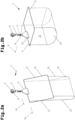
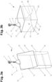
- a conveying material container 2 for transporting a conveying material 28 ( Fig.1 ) which comprises a frame 20 and a bag body attached to the frame 20.
- the frame 20 forms parallel cross struts 21 at a mutual distance and longitudinal struts 22 between the cross struts 21 at a mutual distance.
- the frame 20 forms a substantially rectangular or substantially square outer contour.
- a circumferential wire frame is used as the frame 20.
- the conveyed goods container 2 can also comprise the hanging carrier 13 for hanging transport on the overhead conveyor device 1, which is equipped with a holder 23 for storing the frame 20.
- the frame 20 is mounted with one of the cross struts 21 in the holder 23 on and relative to the hanging carrier 13 about a longitudinal axis 24 of the holder 23.
- the hanging carrier 13 is equipped with the second coupling element 16, for example a suspension element (hook).
- the conveyed goods container 2 can be suspended via the hanging carrier 13 either on the transport carrier 6 or, according to an embodiment not shown, on the overhead conveyor device 1.
- the bag body forms a front wall 25 and a rear wall 26.
- a storage space 27 is delimited by the front wall 25 and rear wall 26.
- the front wall 25 is hingedly attached to the first cross strut 21 at its end and the rear wall 26 is hingedly attached to the second cross strut 21 at its end.
- the ends of the front wall 25 and rear wall 26 that hang downwards from the frame 20 are preferably integrally connected to one another or formed in one piece, so that the front wall 25 and the rear wall 26 merge directly into one another.
- the bag body has on one of the side walls a discharge opening 29 formed at least partially between the front and rear walls 25, 26, through which a conveyed material 28 can be discharged from the conveyed material container 2 ( Fig.6 ).
- the bag body can have on one of the side walls, which is opposite the unloading opening 29, a side wall stop 30 arranged at least partially between the front and rear walls 25, 26, against which the conveyed material 28 can be placed and in order to prevent the conveyed material 28 from falling sideways out of the conveyed material container 2.
- the bag body can be switched between a closed position (transport position) and an open position by pivoting the frame 20.
- the storage space 27 In the closed position, the storage space 27 is volume-minimized (for example Fig.1 - right conveyor container 2 before unloading) and the conveyor material 28 is transported with the conveyor container 2.
- the storage space 27 In the open position, the storage space 27 is volume-maximized ( Fig.5 , 6 - Conveyor container 2 during unloading) and the conveyed material 28 is discharged from the conveyed material container 2 through the discharge opening 29.
- the horizontal distance is smaller than the corresponding horizontal distance in the open position.
- the horizontal distance is reduced to a minimum and results from the geometry/dimensions of the conveyed goods 28, which are received (stowed) in the storage space 27 for transport.
- the storage space 27 (transport space) between the front and rear walls 25, 26 is thus smaller, so that the conveyed goods 28 are reliably held in the storage space 27 by the front and rear walls 25, 26.
- comparatively space-saving transport on the overhead conveyor device 1 is made possible.
- the horizontal distance is greater than the corresponding horizontal distance in the closed position.
- the horizontal distance is preferably increased to a maximum in order to reliably unload the conveyed goods 28 from the storage space 27.
- the pocket body is always switched to the same opening position, which enables a particularly simple construction of the unloading station 4.
- the conveying goods container 2 can be used to transport different conveying goods 28 which vary in geometry/dimensions.
- the conveying goods 28 are, for example, boxes, film bags (so-called “polybags” made of polyethylene or polypropanol) and the like.
- film bags are mainly used in the textile industry and are used, for example, to package T-shirts, shirts and the like.
- the front wall 25 and rear wall 26 of the bag body are preferably made of a flexible material.
- a flexible material can be a fabric (textile), a film, a mesh, a knitted fabric, a woven fabric and/or the like.
- a very light and flexible conveying material container 2 can be provided.
- the conveyed material 28 can be held, in particular clamped, between the front and rear walls 25, 26 by the flexible material, in particular in the closed position.
- the flexible material is preferably pliable and can optionally have elastic properties. This means that the material being conveyed can be tightly surrounded by the flexible material at least in some areas, for example at corners and edges. This can result in a positive and/or force fit to hold the material being conveyed 28 within the pocket body.
- the positive and/or force fit can be reinforced by the gravity of the material being conveyed 28, whereby self-locking can occur.
- a second embodiment of a conveying material container 2 for transporting a conveying material 28 is shown, which differs from the first embodiment in the bag body.
- This comprises a frame 20 and a bag body attached to the frame 20.
- the frame 20 in turn forms cross struts 21 that run parallel at a mutual distance and longitudinal struts 22 that run parallel at a mutual distance between the cross struts 21.
- the frame 20 forms an essentially rectangular or an essentially square outer contour.
- a circumferential wire frame is preferably used as the frame 20.
- the bag body comprises the front wall 25, the rear wall 26 and a base 35.
- the front wall 25 and rear wall 26 of the bag body comprise a flexible material, wherein the flexible material is at least partially stiffened, in particular planked, on the inside or outside in the area of the front wall 25 and/or in the area of the rear wall 26.
- the front wall 25 is divided into a first front wall section (which is further away from the first cross strut 21 than the second front wall section) and a second front wall section (which is closer to the first cross strut 21 than the first front wall section), wherein the front wall 25 is stiffer in the first front wall section than in the second front wall section.
- the rear wall 26 is divided into a first rear wall section (which is further away from the second cross strut 21 than the second Rear wall section) and a second rear wall section (which is closer to the second cross strut 21 than the first rear wall section), wherein the rear wall 26 is more rigid in the second rear wall section than in the first rear wall section.
- the first rear wall section and the first front wall section are arranged adjacent to one another.
- the front wall 25 has a panel which forms the base 35 when the bag body is switched to the open position.
- the first front wall section defines the base 35.
- the panel is attached to the front wall 25, for example sewn or glued. The panel therefore serves to stiffen the flexible material when the bag body is switched to the closed position and as a "slide" when the bag body is switched to the open position.
- the front wall 25 can also form a reinforcement area in which the front wall 25 has a greater material thickness and/or a higher density. This reinforcement area forms the base 35 when the bag body is switched to the open position. According to this embodiment, the front wall 25 forms the base 35.
- first version - floor is formed by a planking and second version - floor is formed by the front wall
- the front wall 25 is provided with the floor 35.
- a panel 34 can be seen in the second rear wall section, which can be provided optionally and in this embodiment serves to stiffen the rear wall 26.
- the panel is attached to the rear wall 26, for example sewn or glued. The panel therefore serves to stiffen the flexible material when the bag body is switched to the closed position.
- the rear wall 26 can also form a reinforcement area in which the rear wall 26 has a greater material thickness and/or a higher density.
- the base 35 has a receiving surface 36 which opens into the discharge opening 29 and facilitates the unloading of the conveyed goods 28.
- the receiving surface 36 can optionally define a sliding surface.
- the conveyed goods 28 can rest on the receiving surface 36.
- the base 35 forms a first longitudinal edge 37a, a second longitudinal edge 37b running at a distance from the first longitudinal edge 37a, a first front edge 38a running between the first longitudinal edge 37a and the second longitudinal edge 37b, and a second front edge 38b running between the first longitudinal edge 37a and the second longitudinal edge 37b.
- the discharge opening 29 is delimited by the front wall 25 and rear wall 26 and borders on the first front edge 38a.
- the first longitudinal edge 37a forms a first folding edge and the second longitudinal edge 37b forms a second folding edge.
- the front wall 25 connects with the second front wall section to the first longitudinal edge 37a and the rear wall 26 connects with the first rear wall section to the second longitudinal edge 37a.
- the pocket body can have a side wall stop 30 adjacent to the second front edge 38b, against which the conveyed material 28 can be placed.
- the storage space 27 of the bag body is delimited by the front wall 25 and the rear wall 26.
- the front wall 25 is hinged at its end (first pivot bearing) to the first long side 22 and the rear wall 26 is hinged at its end (second pivot bearing) to the second long side 22.
- first pivot bearing first pivot bearing
- second pivot bearing second pivot bearing
- the ends of the front wall 25 and the rear wall 26 that hang downwards from the frame 20 are preferably integrally connected to one another or formed in one piece, so that the front wall 25 and the rear wall 26 merge directly into one another.
- the bag body has on one of the side walls the unloading opening 29 formed at least in part between the front and rear walls 25, 26, through which a conveyed material 28 can be discharged from the conveyed material container 2.
- the conveying material container 2 can also comprise the hanging carrier 13 for hanging transport on the overhead conveyor device 1, which is equipped with a receptacle 23 for storing the frame 20, as described above.
- the bag body can be switched between the closed position and the open position by pivoting the frame 20.
- the storage space 27 In the closed position, the storage space 27 is volume-minimized and the conveyed goods 28 are transported with the conveyed goods container 2.
- the storage space 27 In the open position, the storage space 27 is volume-maximized and the conveyed goods 28 are discharged from the conveyed goods container 2 through the discharge opening 29.
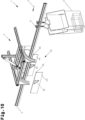
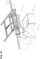
- the unloading station 4 is shown in different views.
- This comprises the overhead conveyor device 1 for transporting the conveyed goods container 2 into the unloading station 4 and transporting the conveyed goods container 2 away from the unloading station 4, a (first embodiment of an) opening and closing device 40 for adjusting the bag body between the closed position and the open position and an unloading device 39 for unloading the bag body adjusted to the open position.
- the opening and closing device 40 comprises an actuating device for automatically opening and closing the bag body, by means of which the frame 20 is relatively to the hanging support 13 about the longitudinal axis 24 such that the bag body can be switched between the closed position and the open position.
- the actuating device for automatically opening and closing the bag body comprises a driver mechanism.
- the driver mechanism preferably comprises a first driver mechanism 41 and a second driver mechanism 42, which are arranged on both sides and below the overhead conveyor device 1 for transporting the conveyed goods container 2 to the unloading station 4 and for transporting the conveyed goods container 2 away from the unloading station 4.
- the first driver mechanism 41 and second driver mechanism 42 are arranged symmetrically to one another with respect to the conveyed goods container 2, in particular the frame 20. In principle, however, only one of the driver mechanisms 41 can be provided.
- the first driver mechanism 41 is attached to a first support frame 43 and the second driver mechanism 42 is attached to a second support frame 44.
- the first support frame 43 and second support frame 44 are part of the actuating device.
- the first driver mechanism 41 comprises a lower guide arrangement and an upper guide arrangement
- the second driver mechanism 42 also comprises a lower guide arrangement and an upper guide arrangement.
- the lower guide arrangement and upper guide arrangement are arranged one above the other at a distance, so that one of the longitudinal struts 22 can be accommodated between the lower guide arrangement and upper guide arrangement of the first driver mechanism 41 and between the lower guide arrangement and upper guide arrangement of the second driver mechanism 42.
- the distance essentially corresponds to the diameter of the longitudinal strut 22.
- the first driver mechanism 41 and/or second driver mechanism 42 can also comprise only the lower guide slot.
- the lower guide arrangement and, if provided, the upper guide arrangement of the first driver mechanism 41 and, if provided, the second driver mechanism 42 comprise, in the transport direction 3 of the conveyed goods container 2, an upstream inlet section 45, a downstream outlet section 46 and an unloading section 47 arranged between the inlet section 45 and the outlet section 46.
- the lower The guide arrangement and, if provided, the upper guide arrangement of the first driver mechanism 41 and/or second driver mechanism 42 run parallel to the transport direction 3 of the conveyed goods container 2.
- the inlet section 45 forms an inclined guide slot 48 which can be brought into contact with the frame 20, in particular the longitudinal struts 22, in such a way that the frame 20 is pivoted during the transport of the conveyed goods container 2 into the unloading station 4, whereby the bag body is moved from the closed position towards the open position ( Fig.4 ).
- the unloading section 47 forms a substantially horizontal guide slot 49 which can be brought into contact with the frame 20, in particular the longitudinal struts 22, in such a way that the frame 20 is held in the pivoted deflection position during the unloading process, whereby the bag body also remains in the open position ( Fig.5 ).
- the outlet section 46 forms an inclined guide slot 50 which can be brought into contact with the frame 20, in particular the longitudinal struts 22, in such a way that the frame 20 is pivoted during the removal of the conveyed goods container 2 from the unloading station 4, whereby the bag body is moved from the open position towards the closed position ( Fig.8 ).
- the outlet section 46 could form a substantially horizontal guide slot 49 that can be brought into contact with the frame 20, in particular the longitudinal struts 22, in such a way that the frame 20 is "suddenly" pivoted during the removal of the conveyed goods container 2 from the unloading station 4 and after leaving the outlet section 46. This allows the bag body to be very quickly switched from the open position to the closed position and the unloading cycle to be accelerated.
- 11a and 11b is the unloading station 4 with the overhead conveyor device 1 for transporting the conveyed goods container 2 into the unloading station 4 and removing the conveyed goods container 2 from the unloading station 4, the unloading device 39 for unloading the bag body adjusted to the open position and a (second embodiment of) opening and closing device 53 for adjusting the bag body between the closed position and the open position.
- the opening and closing device 53 comprises, according to a second embodiment of the actuating device for automatically opening and closing the bag body, at least one by means of a drive 51 (see Fig. 11a, 11b ) between a first flap position ( Fig. 11a ) and a second flap position ( Fig. 11b ) movable opening flap 52 for adjusting the bag body between the closed position and the open position.
- Fig. 11b As can be seen, the conveyor container 2 has already been swivelled into its open position. For this purpose, starting from a Fig. 11a shown position, the opening flap 52 by an angle in a Fig. 11b shown further position is panned.
- the actuation or pivoting of the opening flap 52 between a first flap position and a second flap position is carried out by means of the drive 51.
- the drive 51 can be a stepper motor and/or any other drive.
- the drive 51 and the opening flap 52 are part of an opening and closing device 53 for adjusting the bag body between a closed position ( Fig. 11a ) and an opening position ( Fig. 11b ).
- the actuating device or opening flap 52 for opening the conveyed goods container 2 moves the frame 20 between a starting position and a deflection position.
- the frame 20 In the starting position, the frame 20 is arranged approximately vertically to obliquely depending on the load and in the deflection position it is arranged approximately horizontally.
- the opening flap 52 has a guide web or guide surface 54. This is located in the illustration of the Fig. 11a , i.e. in the closed position of the bag body, in front of the folded down frame 20. In the illustration according to Fig. 11b , i.e. in the
- the frame 20 lies between the guide web 54 and a guide profile 55.
- the frame 20 with the longitudinal struts 21 is fixed force-fittingly between the guide web 54 of the opening flap 52 and the guide profile 55.
- the guide web 54 rests on the frame 20 and holds it in a substantially horizontal position.
- the opening flap comprises a first opening flap 52 and a second opening flap 52, which are controlled synchronously and which are arranged on both sides and below the overhead conveyor device 1 for transporting the conveyed goods container 2 into the unloading station 4 and for transporting the conveyed goods container 2 away from the unloading station 4.
- the first opening flap 52 and the second opening flap 52 are arranged symmetrically to one another with respect to the conveyed goods container 2, in particular the frame 20. This allows the frame 20 to be moved without distortion when the bag body 2 is opened. Heavier conveyed goods 28 can be loaded into the conveyed goods container 2. In principle, however, only one of the opening flaps 52 can be provided.
- the first opening flap 52 is attached to a first support frame 43 and the second opening flap 52 is attached to a second support frame 44.
- Each opening flap 52 is assigned a guide profile 55.
- the guide profiles 55 are arranged on both sides and below the overhead conveyor device 1 for transporting the conveyed goods container 2 into the unloading station 4 and for transporting the conveyed goods container 2 away from the unloading station 4.
- the guide surface 54 running in the transport direction 3 of the conveyed goods container 2 serves to guide the frame 20 when leaving the unloading station 4.
- the guide surface 54 can be used to achieve a desired path of movement of the bag body when leaving the unloading station 4. If necessary, any possible acceleration of the Vibrations and/or oscillations occurring in the conveying material container 2 are dampened, so that an overall quieter ride and thus a more gentle transport of the conveying material 28 within the conveying material container 2 is possible.
- the unloading device 39 comprises an actuating device 56, by means of which the conveying material container 2 with the pocket body is tilted about a tilting axis 57 running essentially parallel to the longitudinal extension of the overhead conveyor device 1 between a provision position 58 ( Fig.5 , 12a ) and an unloading position 59 ( Fig.6 , 12b ) can be tilted, wherein in the unloading position 59 the conveyed goods 28 can be discharged from the conveyed goods container 2 through the unloading opening 29.
- the conveyed goods 28 are preferably loaded into a container (not shown) or onto a conveying device (not shown), for example a belt conveyor. This container can also represent the shipping box.
- the conveying material container 2 with the pocket body adjusted to the open position is rotated about the tilting axis 57 between a ready position 58 ( Fig.5 , 12a ) and an unloading position 59 ( Fig.6 , 12b ) is tilted.
- the pocket body is switched to the open position - the conveyed goods container 2 is now in the ready position 58
- the conveyed goods container 2 with the pocket body adjusted to the open position is pivoted about the tilting axis 57 - the conveyed goods container 2 is now in the unloading position 59.
- the material container 2 with the bag body adjusted to the open position is rotated about the tilting axis 57 from the unloading position 59 ( Fig.6 , 12a ) to the provision position 58 ( Fig.7 ) is tipped back.
- the material container 2 is then transported away by the overhead conveyor device 1.
- the unloading station 4 can be provided with a locking device 70 for locking the transport carrier 6 during an unloading process of the conveyed goods container 2.
- the locking of the transport carrier 6 takes place after the conveyed goods container 2 has reached the ready position 58.
- the conveying material container 2 is tilted about the tilting axis 57 between the ready position 58 and the unloading position 59 during the changeover movement of the pocket body between the closed position and the open position.
- the conveying material container 2 is tilted about the tilting axis 57 from the ready position 58 to the unloading position 59 during the opening process of the pocket body from the closed position in the direction of the open position.
- the conveying material container 2 can be tilted about the tilting axis 57 from the unloading position 59 to the ready position 58 during the closing process of the pocket body from the open position in the direction of the closed position.
- the actuating device 56 of the unloading device 39 comprises a frame 61 which can be tilted by means of a drive 60 about an axis running parallel to the transport direction 3 of the conveyed goods containers 2 between a starting position and an actuating position.
- the drive 60 is, for example, a fluid cylinder.
- the frame 61 is mounted on a stationary support structure 63 via guide arrangements 62.
- the guide arrangements 62 each comprise guide slots 64 and rollable guide rollers 65, 66 ( Fig.1 , 12a ).
- the guide slots comprise the (left) first guide slot 64 and the (right) second guide slot 64.
- the first guide slot 64 is attached to a first support frame 67 and the second guide slot 64 is attached to a second support frame 68.
- the frame 61 has opposite frame sides, with the guide rollers 65, 66 being arranged on the first frame side and the guide rollers 65, 66 being arranged on the second frame side.
- actuating device of the opening and closing device 40; 53 is mounted on the tiltable frame 61.
- first driver mechanism 41 is connected to the first support frame 43 and the second driver mechanism 42 is connected to the second support frame 44 according to the first embodiment or the first opening flap 52 is fastened to the first support frame 43 and the second opening flap 52 is fastened to the second support frame 44 according to the second embodiment via frame connections 69 on the frame 61.
- the opening and closing device 40; 53 is tilted together with the frame 61 and the conveyed goods container 2 is also held essentially fixed in the unloading position 59 (between the lower guide arrangement and upper guide arrangement of the first driver mechanism 41 and, if present, between the lower guide arrangement and upper guide arrangement of the second driver mechanism 42, one of the longitudinal struts 22 according to the first embodiment or between the first opening flap 52 and the first guide profile 55 and, if present, between the second opening flap 52 and the second guide profile 55).
- the unloading station 4 is shown with the first embodiment of the opening and closing device 40.
- the material container 2 is in the ready position 58 and the bag body is in its open position (see also Fig.5 ).
- Fig. 12b the material container 2 is in the unloading position 59 and the bag body is in its opening position (see also Fig.6 ).
- the unloading station 4 additionally comprises a locking device 70 for locking the transport carrier 6 during an unloading process of the conveyed goods container 2.
- the locking device 70 comprises a locking mechanism 71 for locking the transport carrier 6 between an ineffective starting position ( Fig. 12a ) and an effective actuation position ( Fig. 12b ) movable locking element 72.
- the locking element 72 comprises, for example, a stop against which a profile web 73 of the transport carrier 6 runs and positions the transport carrier 6 in the transport direction 3.
- the transport carrier 6 is locked when the conveyed goods container 2 has been stopped and has reached the provision position 58.
- the provision position 58 is monitored by a sensor 74, for example a proximity sensor.
- the unloading station 4 can further comprise a guide device 75 running parallel to the transport direction 3 for laterally guiding the transport carrier 6 during a transport movement of the transport carrier 6 by the overhead conveyor device 1 for transporting the conveyed goods container 2 into the unloading station 4 and for transporting the conveyed goods container 2 away from the unloading station 4.
- the guide device 75 is effective during the unloading process and when the conveyed goods container 2 is tilted about the tilting axis 57 between the provision position 58 and the unloading position 59, in that the transport carrier 6 is fixed against a sideways movement (transverse to the transport direction 3) or a sideways movement (transverse to the transport direction 3) is limited.
- a receiving profile 76 running parallel to the transport direction 3 is provided in the unloading station 4, on which the guide device 75 and/or the sensor system 74 and/or a pressing unit 77 are mounted.
- a friction drive (drive device 5) can be used to drive the transport carrier 6.
- the pressing unit 77 presses the transport carrier 6 against the friction belt 10 with a pressing means acted upon by a spring force.
- the locking element 72 can lift the transport carrier 6 off the friction belt 10 in the actuating position with an unlocking force acting counter to the spring force, so that the conveyed goods container 2 remains in the ready position 58 and is not acted upon by a driving force. It should be expressly pointed out, however, that such a pressing unit 77 can also be omitted.
- the conveyed good containers 2 can be stacked one behind the other in front of the unloading station 4 in the transport direction 3 ( Fig.1 ) and then separated via a singling device (not shown) before one of the conveyed goods containers 2 is transported to the unloading station 4.
- the bag body is moved from the closed position to the open position by the opening and closing device 40.
- the material container 2 is moved by the overhead conveyor 1 in the transport direction 3 and at the unloading station 4 the frame 20 contacts the inlet section 45, so that the transport movement causes the frame 20 to pivot in such a way that the bag body is moved from the closed position towards the open position ( Fig.4 ).
- the frame 20 Due to the continuous transport movement of the conveyed goods container 2, the frame 20 reaches the unloading section 47 and is pivoted in such a way that the bag body is completely moved into the open position and is held in the open position ( Fig.5 ).
- the conveying material container 2 is then stopped briefly. In the stopped position, the conveying material container 2, which has been switched to the open position, is in the ready position 58 ( Fig.5 , 12a ).
- the unloading device 39 tilts the conveyed goods container 2 with the pocket body (according to this embodiment) adjusted to the open position about the longitudinal axis 57 running essentially parallel to the longitudinal extension of the overhead conveyor device 1 from the ready position 58 into the unloading position 59, whereby the conveyed goods 28 are released, in particular ejected, from the conveyed goods container 2 through the unloading opening 29 ( Fig.6 , 12b ). If the locking device 70 is provided, the transport carrier 6 can be locked during the unloading process of the conveyed goods container 2.
- the conveyed goods container 2 is tilted back around the longitudinal axis 57 from the unloading position 59 to the ready position 58 by the unloading device 39 with the bag body adjusted to the open position ( Fig.7 , 12a ). If the locking device 70 is provided, the transport carrier 6 can also be locked during the tipping back (as a step in the unloading process) of the conveyed goods container 2.
- the conveyed goods container 2 is moved by the overhead conveyor device 1 in the transport direction 3 and the frame 20 contacts the outlet section 46, so that the transport movement causes the frame 20 to pivot in such a way that the bag body is moved from the open position towards the closed position ( Fig.8 ). If the locking device 70 is provided, the transport carrier 6 is initially released in order to allow a transport movement in the transport direction 3 again.
- step i) and step ii) are carried out in a temporally overlapping manner in that the conveyed goods container 2 is transported to the unloading station 4 by the overhead conveyor device 1 and is continuously moved along the unloading station 4, wherein during the continuous transport movement of the conveyed goods container 2 in step i) the pocket body 2 is adjusted from the closed position to the open position by the opening and closing device 40, and simultaneously in step ii) the conveyed goods container 2 with the pocket body is tilted by the unloading device 39 about the longitudinal axis 57 running essentially parallel to the longitudinal extension of the overhead conveyor device 1 from the ready position 58 to the unloading position 59, whereby the conveyed goods 28 are released from the conveyed goods container 2 through the unloading opening 29.
- the transport speed varies during the transport movement along the unloading station 4, but is always greater than zero.
- the conveyed goods container 2 is tilted about the tilt axis 57 between the ready position 58 and the unloading position 59 during the changeover movement of the pocket body between the closed position and the open position.
- the conveyed goods container 2 is tilted about the tilt axis 57 from the ready position 58 to the unloading position 59 during the opening process of the pocket body from the closed position in the direction of the open position.
- the conveyed goods container 2 can be tilted about the tilt axis 57 from the unloading position 59 to the ready position 58.
- the locking device 70 described above for locking the transport carrier 6 can be omitted.
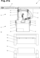
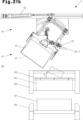
- 21a , 21b and 21c a section of a hanging conveyor system comprising the hanging conveyor device 1 for transporting goods containers 2 in the transport direction 3 and a modified version of an unloading station 4' for automatically unloading the goods containers 2 (transport bag or hanging bag) is shown.
- the hanging conveyor device 1 shown for transporting the conveyed goods containers 2 into the unloading station 4' and transporting the conveyed goods containers 2 away from the unloading station 4' comprises, in various conveyor sections 80a, 80b, 80c, a guide device 81 and transport supports 6 that can be moved (driven) along the guide device 81 by one of the drive devices 5 described above or a combination of the drive devices 5 described above.
- the overhead conveyor system can also comprise an overhead conveyor device (not shown) for transporting containers 2 to be conveyed, which has a guide device 81 and transport supports 6 that can be moved along the guide device 81 (not driven).
- an overhead conveyor device (not shown) for transporting containers 2 to be conveyed, which has a guide device 81 and transport supports 6 that can be moved along the guide device 81 (not driven).
- the overhead conveyor system can also comprise exclusively the guide device 81 and transport carriers 6 that can be moved (driven) along the guide device 81 by the drive device(s) 5 described above.
- Such a transport carrier 6 is described, for example, in the Austrian patent application AT50092/2019 described.
- the guide device 81 is formed on the profile rail 11.
- the transport carriers 6 can also be moved in the upstream conveyor section 80a (for transporting the conveyed goods containers 2) as well as in the downstream conveyor section 80b (for removing the conveyed goods containers 2) by a positive drive (drive device).
- a guide bar 90 described below and arranged in the conveyor section 80c can be omitted.
- the conveyor section 80c forms a transport path 82 parallel to the longitudinal extension of the overhead conveyor device 1 and along the removal station 4', along which the conveyed goods containers 2 are transported, in particular individually.
- the drive devices described are in no way to be understood as limiting, but merely show different possibilities of how a drive force is transmitted to the transport carriers 6 or the conveyed goods containers 2 in order to move them on the overhead conveyor device 1 in the transport direction 3 (driven).
- the drive device 5 is formed by a friction drive
- the guide device 81 in the conveyor section 80c has a guide bar 90 running parallel to the transport direction 3, by means of which the transport carrier 6 is lifted in a vertical direction to and from the friction belt 10, as shown in particular in the Fig. 13 and 22
- the transport carrier 6 is supported on the guide bar 90 in the ready position 58 and unloading position 59 of the conveyed goods container 2 and thus the unloading process can be carried out particularly reliably, as in Fig. 21a and 21b visible.
- the conveyed goods container 2 in the conveying section 80c can in principle also be moved by a friction and form-fitting drive.
- the drive device 5 in the conveyor section 80c comprises a feed drive 83, as shown in Fig. 23 shown in more detail.
- the feed drive 83 comprises a support frame 84, a traction mechanism drive mounted on the support frame 84 and a driver finger arranged with a traction mechanism 85 for driving the transport carrier 6 or the conveyed goods container 2 along the guide device 81.
- the traction mechanism drive comprises the traction mechanism 85, which is guided around a drive wheel 87 and deflection wheels 88.
- the drive wheel 87 is coupled to a drive motor 89.
- the feed drive 83 can also comprise a sensor 74, for example a proximity sensor, by which the provision position 59 is monitored.
- the driver finger can be moved by the traction drive between a starting position retracted from the transport path 82 and an engagement position protruding into the transport path 82, wherein the driver finger can be brought into a positive engagement with the conveying goods container 2 in the engagement position and by means of which the conveying goods container 2 can be moved along the conveying section 81c.
- the driver finger can comprise a first driver finger 86-1 and a second driver finger 86-2, which are arranged in the direction of rotation of the traction means 85 at a distance which is determined such that the plurality of driver fingers 86-1, 86-2 are alternately moved into the engagement position, wherein the respective driver finger 86-1, 86-2 can be brought into positive engagement with the conveyed goods container 2 in the engagement position and by means of which the conveyed goods container 2 can be moved along the conveying section 81c.
- Fig. 16 shows the driver finger 86-1 in the engagement position and Fig. 23 the driver finger 86-1 in the starting position.
- the first driver finger 86-1 can be brought into positive engagement with a first conveyed goods container 2 and moves the first conveyed goods container 2 along the conveying section 81c, see Fig. 16 and 17
- the second driver finger can be brought into positive engagement with a second conveyed goods container 2 and moves the second conveyed goods container 2 along the conveying section 81c.
- the first conveyed goods container 2 and the second conveyed goods container 2 are therefore transported one after the other through the conveying section 81c, but as soon as the first conveyed goods container 2 is transported out of the conveying section 81c by the first driver finger 86-1, the second conveyed goods container 2 can already be gripped by the second driver finger 86-2.
- the number of driving fingers can vary. More than two driving fingers can also be provided. A single driving finger is also conceivable.
- the modified version of the unloading station 4' comprises, like the unloading station 4, the overhead conveyor device 1 for transporting the conveyed goods container 2 into the unloading station 4' and for transporting the conveyed goods container 2 away from the unloading station 4', the opening and closing device 40; 53 for adjusting the bag body between the closed position and the open position and the unloading device 39 for unloading the bag body adjusted to the open position.
- the opening and closing device 40 for adjusting the bag body between the closed position and the open position
- the unloading device 39 for unloading the bag body adjusted to the open position.
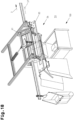
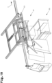
- the unloading device 39 corresponds to the embodiment described above and comprises the actuating device 56, by means of which the conveyed goods container 2 with the pocket body is tilted about a tilting axis 57 running essentially parallel to the longitudinal extension of the overhead conveyor device 1 between the provision position 58 ( Fig. 17 , 21a ) and the unloading position 59 ( Fig. 18 , 21b ) is tiltable, wherein in the unloading position 59 the conveyed material 28 can be discharged from the conveyed material container 2 through the unloading opening 29.
- the actuating device 56 by means of which the conveyed goods container 2 with the pocket body is tilted about a tilting axis 57 running essentially parallel to the longitudinal extension of the overhead conveyor device 1 between the provision position 58 ( Fig. 17 , 21a ) and the unloading position 59 ( Fig. 18 , 21b ) is tiltable, wherein in the unloading position 59 the conveyed material 28 can be discharged from the
- the actuating device 56 of the unloading device 39 comprises the frame 61, which can be tilted by means of a drive 60 about an axis running parallel to the transport direction 3 of the conveyed goods containers 2 between a starting position and an actuating position, as described above.
- the drive device 5 comprises the feed drive 83 described above, in which case the actuating device 41, 42; 52 of the opening and closing device 40; 53 and the feed drive 83 are mounted on the frame 61.
- the feed drive 83 and the opening and closing device 40; 53 are tilted together with the frame 61 and the conveyed goods container 2 is also held essentially fixed in the unloading position 59 (between the lower guide arrangement and upper guide arrangement of the first driver mechanism 41 and, if present, between the lower guide arrangement and upper guide arrangement of the second driver mechanism 42, one of the longitudinal struts 22 according to the first embodiment or between the first opening flap 52 and the first guide profile 55 and, if present, between the second opening flap 52 and the second guide profile 55).
- the unloading station 4' in the conveying section 80c upstream of the opening and closing device 40; 53 may comprise a conveying goods container positioning device 91.
- the conveyed goods container positioning device 91 comprises stopper elements 93 arranged on both sides of the transport path 82 and symmetrically to a vertical plane 92 running in the direction of the transport path 82.
- the stopper elements 93 are moved by a drive 94 between a release position retracted from the transport path 82 ( Fig. 15 , 16 ) and an engagement position projecting into the transport path 82 ( Fig. 13 , 14 ) movable.
- the stopper elements 93 are designed as stopper fingers or stopper plates. As can be seen in the figures, the stopper elements 93 are each coupled to a drive 94. The stopper elements 93 can, for example, each be pivoted about a vertical axis by the drive 94. The stopper elements 93 can, however, also be designed as stopper plates that can be moved perpendicular to the vertical plane 92 and toward and away from each other by drives, as is not shown in more detail.
- the positioning of the conveyed goods container 2 against the stopper elements 93 can be carried out in such a way that the conveyed goods container 2 is positioned with a frame 20 having these, with which the pocket body can be switched between the closed position and the open position, and/or with a pocket body against the stopper fingers 93 moved into the engagement position.
- a (preferably) individually transported material container 2 can be positioned against the stopper fingers.
- the material container 2 is now in a takeover position ( Fig. 14 ), in which the feed drive 83 described above with the driver finger 86-1 grips the conveyed goods container 2 and by means of which the conveyed goods container 2 is moved from the take-over position to a downstream provision position 58 ( Fig. 17 ) can be moved.
- the transport carrier 6 is moved by the drive device provided in the conveyor section 80a 5 and thus the conveyed goods container 2 is positioned against the stopper elements 93 moved into the engagement position.
- the transport carrier 6 in the conveying section 80a is driven by the endlessly rotating friction belt 10.
- the conveyed goods container 2 can be moved from the ready position 58 ( Fig. 17 ) into a transfer position provided downstream of this ( Fig. 20 ), at which the conveyed goods container 2 enters the conveying section 80b.
- the transport carrier 6 is driven by the drive device 5 provided in the conveying section 80b and thus the conveyed goods container 2 is transported away from the unloading station 4'.
- the transport carrier 6 in the conveying section 80b is driven by the endlessly rotating friction belt 10.
- the unloading station 4' can also have the locking device 70 described above for locking the transport carrier 6 during an unloading process of the conveyed goods container 2.
- the locking device 70 comprises a locking element 72 for locking the transport carrier 6, which can be moved by means of a drive 71 between an ineffective starting position and an effective actuating position.
- the locking element 72 comprises, for example, a stop against which the transport carrier 6 moved by the feed drive 83 runs and by which the transport carrier 6 is positioned in the transport direction 3.
- the transport carrier 6 is now positioned between the driver finger 86-1 arranged upstream of the transport carrier 6 and the locking element 72 arranged downstream of the transport carrier 6.
- the conveyed goods container 2 is now in the ready position 58 ( Fig. 17 ), in which the transport carrier 6 is locked.
- the provision position 58 will be discussed in Fig. 23 shown sensor system 74, for example a proximity sensor.
- locking is to be understood in such a way that the transport carrier 6 does not necessarily have to be fixed in the ready position 58, but can also be moved to a limited extent between the driver finger 86-1 and locking element 72. Nevertheless, sufficient positioning between the driver finger 86-1 and locking element 72 is provided and the unloading process can be carried out reliably even with highly dynamic tilting movements.
- the conveying goods container positioning device 91 can also comprise guide walls 96 arranged on both sides of the transport path 82 and symmetrically to a vertical plane 92 running in the direction of the transport path 82.
- the guide walls 96 form inlet slopes 97 which are arranged symmetrically to the vertical plane 92 running in the direction of the transport path 82 and which converge at an angle towards one another in the direction of the opening and closing device 40; 53.
- At least one of the guide walls 96 is provided with a driver mechanism 98, wherein the driver mechanism 98 forms an inclined guide slot 99 that can be brought into contact with the frame 20 in such a way that the frame 20 is pivoted into the opening and closing device 40; 53 during the transport of the conveyed goods container 2, whereby the bag body is switched from the closed position towards the open position.
- the bag body is not necessarily yet completely switched into the open position.
- the driver mechanism 98 comprises a first driver mechanism and a second driver mechanism, which are arranged on both sides of the transport path 82 and symmetrically to a vertical plane 92 running in the direction of the transport path 82, and which each form an inclined guide slot 99 that can be brought into contact with the frame 20, as in Fig. 16 visible.
- the unloading station 4' can additionally comprise a filling device 100 below the unloading position (or picking position), by means of which in a first step i) the conveyed goods 28 dropped from the conveyed goods container 2 are picked up and in a second Step ii) the conveyed material 28 is delivered to a receiving container 101, see in particular the Fig. 21a , 21b , 21c .
- the receiving container 101 can be formed, for example, by a container which is filled by a container arranged below the filling device 100 (exclusively in the Fig. 21a , 21b , 21c shown) conveyor device 102 into a filling position and is transported away from the filling position after filling.
- the filling device 100 comprises a storage base 103 and a base opening 104 that can be opened and closed by the storage base 103.
- the storage base 103 comprises, for example, base parts that can be pivoted in opposite directions about axes aligned transversely to the transport direction 3 (as in Fig. 19 clearly visible).
- the conveyed goods 28 slide on the floor 35 in the direction of the discharge opening 29 and then fall at an angle " ⁇ " of less than 60°, in particular at an angle " ⁇ " between 30° and 45° relative to a horizontal plane onto the storage floor 103 of the filling device 100, as shown in Fig. 21b
- the angle " ⁇ " results from the tilt angle of the conveying material container 2 when it is tilted into the unloading position 59.
- This method step comprises positioning the conveyed goods container 2 against the stopper elements 93 moved into the engagement position projecting into the transport path 82, specifically before the bag body is moved from the closed position to the open position (step i)), as is particularly shown in the Fig. 14 is evident.
- the unloading in step ii) can be carried out in such a way that in the unloading position 59 of the conveyed goods container 2, the conveyed goods 28 are initially transferred from the conveyed goods container 2 to the Filling device 100 and subsequently from the filling device 100 to a receiving container 101 provided below the filling device 100, as is particularly shown in the Fig. 21a and 21c is evident.
- the unloading station 4; 4' described above is arranged along a suspended conveyor system, which comprises the unloading station 4; 4' and at least the suspended conveyor device 1 for transporting the conveyed goods containers into the unloading station 4; 4' and for transporting the conveyed goods containers 2 away from the unloading station 4; 4'.
- the suspended conveyor system can also comprise the suspended conveyor device 1 for transporting the conveyed goods containers 2 into the unloading station 4; 4' and for transporting the conveyed goods containers 2 away from the unloading station 4; 4', a conveyor arranged upstream of the conveyor (indicated by dashed lines in Fig.1 indicated) overhead conveyor device for transporting containers 2 and a downstream conveyor device (indicated by dashed lines in Fig.1 indicated) overhead conveyor device for transporting containers 2.
- the overhead conveyor devices are in Fig.1 shown separately for the sake of clarity. In fact, the overhead conveyors are directly connected to one another.
- conveying container positioning device 91 and/or the filling device 100 and/or the conveying device 102 can also be arranged in the unloading station 4 ( Fig. 1 to 11 , 12a , 12b ) can be applied.
- the overhead conveyor system can comprise an overhead conveyor device 1 as described above for transporting conveyed goods containers 2 and a loading station for loading the conveyed goods containers 2, as not shown in more detail.
- the loading station is designed like the unloading station 4; 4', with the only difference that the actuating device 56 is omitted.
- the loading station comprises in any case the above-described overhead conveyor device 1 for transporting the conveyed goods containers 2 into the loading station and for transporting the conveyed goods containers 2 away from the loading station, the above-described opening and closing device 40 and the above-described conveyed goods container positioning device 91. If the feed drive 83 is also provided, it is arranged stationary.
- a conveying device for example a belt conveyor, is also provided, the conveying direction of which runs essentially perpendicular to the vertical plane 92.
- the conveyed goods 28 can be placed on the conveying device either manually by a person or automatically by a robot.
- the conveying material container 2 can be opened after the bag body has been moved out of the closed position ( Fig. 3a ) to the open position ( Fig. 3b ), can be loaded via the unloading opening 29, which in this case also forms a loading opening.
- a conveying plane of the conveying device preferably runs slightly higher than the floor 35. It can also be provided that a baffle wall aligned parallel to the vertical plane 92 is provided on a side opposite the loading opening in order to prevent a conveyed item 28 from falling out of the bag body during the loading process. The conveyed item 28 therefore does not necessarily have to be positioned against the side wall stop 29 when the conveyed item container 2 is loaded.
- the bag body is moved from the open position to the closed position by the opening and closing device 40 and the material 28 to be conveyed is held between the front wall 25 and the rear wall 26.
Landscapes
- Engineering & Computer Science (AREA)
- Mechanical Engineering (AREA)
- Supplying Of Containers To The Packaging Station (AREA)
- Intermediate Stations On Conveyors (AREA)
- Warehouses Or Storage Devices (AREA)
- Chain Conveyers (AREA)
- Control And Other Processes For Unpacking Of Materials (AREA)
- Specific Conveyance Elements (AREA)
Claims (20)
- Station de déchargement (4 ; 4') pour le déchargement d'un récipient de produit transporté (2) chargé avec au moins un produit transporté (28),ce récipient de produit transporté (2) comprenant- un corps de sac avec une paroi avant (25) et une paroi arrière (26),- un espace de conservation (27) délimité par la paroi avant (25) et la paroi arrière (26) et- une ouverture de déchargement (29) réalisée sur le corps de sac au moins à certains endroits entre les parois avant et arrière (25, 26), dans lequel le corps de sac peut être commuté entre une position de fermeture, dans laquelle l'espace de conservation (27) présente un volume minimal et le produit transporté (28) peut être transporté avec le récipient de produit transporté (2) et une position d'ouverture, dans laquelle l'espace de conservation (27) présente un volume maximal et le produit transporté (28) peut être distribué à travers l'ouverture de déchargement (29) hors du récipient de produit transporté,cette station de déchargement (4 ; 4') comprenant- un dispositif de transport suspendu (1) pour le transport du récipient de produit transporté (2) vers la station de déchargement (4 ; 4') et le transport du récipient de produit transporté (2) hors de la station de déchargement (4 ; 4'),- un dispositif d'ouverture et de fermeture (40 ; 53) pour le déplacement du corps de sac entre la position de fermeture et la position d'ouverture et- un dispositif de déchargement (39) pour le déchargement du récipient de produit transporté (2),dans lequel le dispositif de déchargement (39) comprend un dispositif d'actionnement (56) par l'intermédiaire duquel le récipient de produit transporté (2) avec le corps de sac peut être basculé autour d'un axe de basculement (57) entre une position de mise à disposition (58) et une position de déchargement (59) etdans lequel, dans la position de déchargement (59), le produit transporté (28) peut être distribué à travers l'ouverture de déchargement (29) hors du récipient de produit transporté (2),caractérisé en ce quel'ouverture de déchargement (29) est réalisée latéralement sur le corps de sac etl'axe de basculement (57) s'étend de manière globalement parallèle à l'extension longitudinale du dispositif de transport suspendu (1).
- Station de déchargement selon la revendication 1, caractérisé en ce que le récipient de produit transporté (2) comprend en outre- un support suspendu (13) pour le transport suspendu sur le dispositif de transport suspendu (1) et avec un logement (23) et- un châssis (20) par l'intermédiaire duquel le corps de sac est suspendu au support suspendu (13) et qui est logé de manière pivotante dans le logement (23) sur et par rapport au support suspendu (13) autour d'un axe longitudinal (24) du logement (23), ce qui permet de commuter le corps de sac entre la position de fermeture et la position d'ouverture.
- Station de déchargement selon la revendication 2, caractérisé en ce que le châssis (20) comprend des entretoises transversales (21) et des entretoises longitudinales (22) et en ce que la paroi avant (25) et la paroi arrière (26) du corps de sac sont montées respectivement sur une des entretoises transversales (21) du châssis (20).
- Station de déchargement selon l'une des revendications 1 à 3, caractérisé en ce que le dispositif d'ouverture et de fermeture (40 ; 53) comprend un dispositif d'actionnement (41, 42 ; 52) pour l'ouverture et la fermeture automatique du corps de sac, par l'intermédiaire de laquelle le châssis (20) peut pivoter par rapport au support suspendu (13) autour de l'axe longitudinal (24), de sorte que le corps de sac peut être commuté entre la position de fermeture et la position d'ouverture.
- Station de déchargement selon la revendication 1, caractérisé en ce que le dispositif d'actionnement (56) du dispositif de déchargement (39) comprend un cadre (61) pouvant être basculé, au moyen d'un entraînement (60), autour d'un axe s'étendant parallèlement à la direction de transport (3) des récipients de produit transporté (2), entre une position initiale et une position d'actionnement et le dispositif d'actionnement (41, 42 ; 52) du dispositif d'ouverture et de fermeture (40 ; 53) est logé sur le cadre (61).
- Station de déchargement selon l'une des revendications 1 à 5, caractérisé en ce que le dispositif de transport suspendu (1) comprend, pour le transport du récipient de produit transporté (2) vers la station de déchargement (4 ; 4') et le transport du récipient de produit transporté (2) hors de la station de déchargement (4 ; 4') comprend un dispositif de guidage (81) et des supports de transport (6) pouvant être déplacés par un dispositif d'entraînement (5) le long du dispositif de guidage (81).
- Station de déchargement selon la revendication 6, caractérisé en ce que le dispositif d'entraînement (5) comprend, dans une portion de transport (80c) le long de la station de déchargement (4'), un entraînement d'avance (83), cet entraînement d'avance (83)- un cadre de support (84),- une transmission à moyen de traction logé sur le cadre de support (84) avec un moyen de traction (85) pouvant être entraîné par un moteur d'entraînement (89) et- au moins un taquet d'entraînement (86-1, 86-2) couplé avec le moyen de traction (85), pour le mouvement d'entraînement du récipient de produit transporté (2) le long du dispositif de guidage (81).
- Station de déchargement selon la revendication 7, caractérisé en ce que la portion de transport (80c) forme un trajet de transport (82) le long duquel les récipients de produit transporté (2) sont transportés et en ce qu'au moins un taquet d'entraînement (86-1, 86-2) peut être déplacé par la transmission à moyen de traction entre une position initiale retirée hors du trajet de transport (82) et une position d'emboîtement dépassant dans le trajet de transport (82), dans laquelle l'au moins un taquet d'entraînement (86-1, 86-2), peut être mis, dans la position d'emboîtement, en emboîtement par complémentarité de forme avec le support de transport (6) ou le récipient de produit transporté (2) et par l'intermédiaire duquel le récipient de produit transporté (2) peut être déplacé le long de la portion de transport (80c).
- Station de déchargement selon la revendication 7, caractérisé en ce que le dispositif d'actionnement (56) du dispositif de déchargement (39) comprend un cadre (61) pouvant être basculé, au moyen d'un entraînement (60) autour d'un axe s'étendant parallèlement à la direction de transport (3) des récipients de produit transporté (2) entre une position initiale et une position d'actionnement et en ce que le dispositif d'actionnement (41, 42 ; 52) du dispositif d'ouverture et de fermeture (40 ; 53) ainsi que l'entraînement d'avance (83) sont logés sur le cadre (61).
- Station de déchargement selon l'une des revendications 6 à 9, caractérisé en ce que, dans une portion de transport (80c), le long de la station de déchargement (4 ; 4') et en amont du dispositif d'ouverture et de fermeture (40 ; 53), est prévu un dispositif de positionnement de récipient de produit transporté (91).
- Station de déchargement selon la revendication 10, caractérisé en ce que la portion de transport (80c) forme un trajet de transport (82) le long duquel les récipients de produit transporté (2) sont transportés et en ce que le dispositif de positionnement de récipient de produit transporté (91) comprend des éléments de butée (93), plus particulièrement des taquets de butée, disposés des deux côtés du trajet de transport (82) et symétriquement par rapport à un plan vertical (92) s'étendant en direction du trajet de transport (82), qui peuvent être déplacés, à l'aide d'au moins un entraînement (94), entre une position de libération retirée hors du trajet de transport (82) et une position d'emboîtement dépassant dans le trajet de transport (82), dans laquelle le récipient de produit transporté (2) peut être positionné contre les éléments de butée (93) déplacés vers la position d'emboîtement.
- Station de déchargement selon l'une des revendications 6 à 11, caractérisé en ce que, dans une portion de transport (80c), le long de la station de déchargement (4 ; 4') et en amont du dispositif d'ouverture et de fermeture (40 ; 53), est prévu un dispositif de guidage de récipient de produit transporté (91).
- Station de déchargement selon l'une des revendications 6 à 12, caractérisé en ce que la station de déchargement (4 ; 4') comprend en outre, en dessous de la position de déchargement, un dispositif de remplissage (100), à l'aide de laquelle, dans une première étape i) le produit transporté (28) éjecté du récipient de produit transporté (2) est logé et, dans une deuxième étape ii) le produit transporté (28) est distribué au niveau d'un récipient de logement (101).
- Station de déchargement selon la revendication 13, caractérisé en ce que la station de déchargement (4 ; 4') comprend en outre un dispositif de transport (102) pour le transport d'un récipient de logement (101) vers une position de remplissage et le transport d'un récipient de logement (101) hors de la position de remplissage, qui est disposé en dessous du dispositif de remplissage (102).
- Procédé de déchargement d'un produit transporté (28) hors d'un récipient de produit transporté (2) vers une station de déchargement (4 ; 4')ce récipient de produit transporté (2) comprenant- un corps de sac avec une paroi avant (25) et une paroi arrière (26),- un espace de conservation (27) délimité par la paroi avant (25) et la paroi arrière (26) et- une ouverture de déchargement (29) réalisée sur le corps de sac au moins à certains endroits entre les parois avant et arrière (25, 26), dans lequel le corps de sac peut être commuté entre une position de fermeture, dans laquelle l'espace de conservation (27) présente un volume minimal et le produit transporté (28) peut être transporté avec le récipient de produit transporté (2) et une position d'ouverture, dans laquelle l'espace de conservation (27) présente un volume maximal et le produit transporté (28) peut être distribué à travers l'ouverture de déchargement (29) hors du récipient de produit transporté,cette station de déchargement (4 ; 4') comprenant- un dispositif de transport suspendu (1) pour le transport du récipient de produit transporté (2) vers la station de déchargement (4 ; 4') et le transport du récipient de produit transporté (2) hors de la station de déchargement (4 ; 4'),- un dispositif d'ouverture et de fermeture (40 ; 53) pour le déplacement du corps de sac entre la position de fermeture et la position d'ouverture et- un dispositif de déchargement (39) pour le déchargement du récipient de produit transporté (2),dans lequel le récipient de produit transporté (2) est transporté par le dispositif de transport suspendu (1) vers la station de déchargement (4 ; 4') et est déchargé au niveau de la station de déchargement (4 ; 4') et, après un processus de déchargement, le récipient de produit transporté (2) est transporté par le dispositif de transport suspendu (1) hors de la station de déchargement (4 ; 4'),dans lequel, pour le déchargement d'un produit transporté (28) hors d'un récipient de produit transporté (2)i) dans une étape, le dispositif d'ouverture et de fermeture (40 ; 53) déplace le corps de sac de la position de fermeture vers la position d'ouverture etii) dans une étape, le récipient de produit transporté (2) est basculé par le dispositif de déchargement (39) avec le corps de sac autour d'un axe de basculement (57) d'une position de mise à disposition (58) vers une position de déchargement (59), ce qui permet de distribuer le produit transporté (28) à travers l'ouverture de déchargement (29) hors du récipient de produit transporté (2),caractérisé en ce quel'ouverture de déchargement (29) est réalisée latéralement sur le corps de sac etl'axe de basculement (57) s'étend de manière globalement parallèle à l'extension longitudinale du dispositif de transport suspendu (1).
- Procédé de déchargement d'un produit transporté selon la revendication 15, caractérisé en ce que l'étape i) et l'étape ii) sont exécutées successivement dans le temps, le récipient de produit transporté (2) étant transporté par le dispositif de transport suspendu (1) vers la station de déchargement (4 ; 4') et étant arrêté au niveau de la station de déchargement (4 ; 4') puis- dans la première étape i), le corps de sac est déplacé par le dispositif d'ouverture et de fermeture (40 ; 53) de la position de fermeture vers la position d'ouverture puis- dans la deuxième étape ii) le récipient de produit transporté (2) est basculé par le dispositif de déchargement (39), avec le corps de sac déplacé vers la position d'ouverture, autour de l'axe de basculement (57) s'étendant de manière globalement parallèle à l'extension longitudinale du dispositif de transport suspendu (1), de la position de mise à disposition (58) vers la position de déchargement (59), ce qui permet de distribuer le produit transporté (28) à travers l'ouverture de déchargement (29) hors du récipient de produit transporté (2).
- Procédé de déchargement d'un produit transporté selon la revendication 15, caractérisé en ce que l'étape i) et l'étape ii) sont exécutées simultanément, le récipient de produit transporté (2) étant transporté par le dispositif de transport suspendu (1) vers la station de déchargement (4 ; 4') et étant déplacé en continu au niveau de la station de déchargement (4 ; 4'), dans lequel, pendant le mouvement de transport en continu du récipient de produit transporté (2)- dans l'étape i), le corps de sac est déplacé par le dispositif d'ouverture et de fermeture (40 ; 53) de la position de fermeture vers la position d'ouverture et simultanément- dans l'étape ii) le récipient de produit transporté (2) est basculé par le dispositif de déchargement (39), avec le corps de sac autour de l'axe de basculement (57) s'étendant de manière globalement parallèle à l'extension longitudinale du dispositif de transport suspendu (1), de la position de mise à disposition (58) vers la position de déchargement (59), ce qui permet de distribuer le produit transporté (28) à travers l'ouverture de déchargement (29) hors du récipient de produit transporté (2).
- Procédé de déchargement d'un produit transporté selon l'une des revendications 15 à 17, caractérisé en ce que, après le déchargement du récipient de produit transporté (2)- dans une étape iii), le récipient de produit transporté (2) est rebasculé, par le dispositif de déchargement (39), avec le corps de sac, autour d'un axe de basculement (57) s'étendant de manière globalement parallèle à l'extension longitudinale du dispositif de transport suspendu (1), de la position de déchargement (59) vers la position de mise à disposition (58) et- dans une étape iv), le corps de sac est déplacé par le dispositif d'ouverture et de fermeture (40 ; 53) de la position d'ouverture vers la position de fermeture.
- Procédé de déchargement d'un produit transporté selon l'une des revendications 15 à 18, caractérisé en ce que, dans une portion de transport (80c) le long de la station de déchargement (4 ; 4') et en amont du dispositif d'ouverture et de fermeture (40 ; 53), est prévu un dispositif de positionnement de récipient de produit transporté (91), qui comprend des éléments de butée (93), plus particulièrement des taquets de butée, disposés des deux côtés du trajet de transport (82) et symétriquement par rapport à un plan vertical (92) s'étendant en direction du trajet de transport (82), qui peuvent être déplacés, à l'aide d'au moins un entraînement (94), entre une position de libération retirée hors du trajet de transport (82) et une position d'emboîtement dépassant dans le trajet de transport (82), dans lequel, avant l'étape i), le récipient de produit transporté (2) peut être positionné contre les éléments de butée (93) déplacés vers la position d'emboîtement dépassant dans le trajet de transport (82).
- Procédé de déchargement d'un produit transporté selon l'une des revendications 15 à 19, caractérisé en ce que, en outre, en dessous de la position de déchargement, est prévu un dispositif de remplissage (100), dans lequel dans l'étape ii), le produit transporté (28) est d'abord distribué du récipient de produit transporté (2) vers le dispositif de remplissage (100) puis du dispositif de remplissage (100) vers un récipient de logement (101) mis à disposition en dessous du dispositif de remplissage (100).
Applications Claiming Priority (3)
| Application Number | Priority Date | Filing Date | Title |
|---|---|---|---|
| ATA50320/2018A AT520517B1 (de) | 2018-04-13 | 2018-04-13 | Entladestation und Verfahren zum Entladen eines mit einem Fördergut beladenen Fördergutbehälters |
| ATA50109/2019A AT521110B1 (de) | 2018-04-13 | 2019-02-13 | Entladestation und Verfahren zum Entladen eines mit einem Fördergut beladenen Fördergutbehälters |
| PCT/AT2019/060121 WO2019195871A1 (fr) | 2018-04-13 | 2019-04-09 | Poste de déchargement et procédé destiné au déchargement d'un récipient de produit à transporter chargé avec un produit à transporter |
Publications (3)
| Publication Number | Publication Date |
|---|---|
| EP3774601A1 EP3774601A1 (fr) | 2021-02-17 |
| EP3774601B1 true EP3774601B1 (fr) | 2024-09-04 |
| EP3774601C0 EP3774601C0 (fr) | 2024-09-04 |
Family
ID=66476946
Family Applications (1)
| Application Number | Title | Priority Date | Filing Date |
|---|---|---|---|
| EP19725839.5A Active EP3774601B1 (fr) | 2018-04-13 | 2019-04-09 | Poste de déchargement et procédé destiné au déchargement d'un récipient de produit à transporter chargé avec un produit à transporter |
Country Status (6)
| Country | Link |
|---|---|
| US (1) | US11352216B2 (fr) |
| EP (1) | EP3774601B1 (fr) |
| CN (1) | CN111936400B (fr) |
| AT (2) | AT520517B1 (fr) |
| ES (1) | ES2996221T3 (fr) |
| WO (1) | WO2019195871A1 (fr) |
Families Citing this family (23)
| Publication number | Priority date | Publication date | Assignee | Title |
|---|---|---|---|---|
| US11878876B2 (en) * | 2017-01-31 | 2024-01-23 | Ferag Ag | Device for emptying transport bags conveyed in a suspended manner |
| DE112019003084A5 (de) | 2018-06-21 | 2021-04-15 | Tgw Logistics Group Gmbh | Lager- und kommissioniersystem sowie kommissionierverfahren mit verbessertem warentransfer zwischen zwei lagerbereichen |
| CA3104334A1 (fr) | 2018-06-21 | 2019-12-26 | Tgw Logistics Group Gmbh | Systeme de stockage et de preparation de commandes et procede de preparation de commandes avec transfert ameliore des marchandises entre deux zones de stockage |
| EP3810530B2 (fr) | 2018-06-21 | 2026-03-18 | TGW Logistics GmbH | Système d'emmagasinage et de préparation de commandes et procédé de préparation de commandes d'articles commandés provenant d'un sac suspendu et d'un autre moyen de chargement |
| CH715134A1 (de) * | 2018-06-28 | 2019-12-30 | Ferag Ag | Vorrichtung und Verfahren zur Inspektion von hängend förderbaren Transporttaschen. |
| EP3826943B1 (fr) | 2018-07-23 | 2022-06-08 | TGW Logistics Group GmbH | Système d'entreposage et de préparation de commandes présentant un temps de cycle réduit et procédé de fonctionnement de celui-ci |
| DE112019006556A5 (de) | 2019-01-04 | 2021-10-14 | Tgw Logistics Group Gmbh | Kommissionierstation und verfahren zum automatischen kommissionieren und automatischen verpacken von waren |
| AT521961B1 (de) * | 2019-01-25 | 2020-07-15 | Tgw Mechanics Gmbh | Fördergutbehälter für eine Hängefördervorrichtung und Entladestation zum Entladen desselben |
| AT522067B1 (de) | 2019-02-07 | 2020-08-15 | Tgw Mechanics Gmbh | Transportträgersystem und Hängefördervorrichtung mit Transportträgern zum Transport von Hängewaren |
| CN113423654B (zh) | 2019-02-11 | 2023-02-10 | Tgw物流集团有限公司 | 具有改进的入库性能的存放和拣选系统和用于运行其的方法 |
| AT522665B1 (de) * | 2019-05-22 | 2021-12-15 | Tgw Mechanics Gmbh | Hängefördersystem und Verfahren zum Bestimmen der Dicke einer Hängetasche |
| CH716519A1 (de) * | 2019-08-22 | 2021-02-26 | Ferag Ag | Vorrichtung und Verfahren zum Transferieren von Waren-Einheiten in Fördereinheiten und/oder aus Fördereinheiten eines Hängefördersystems. |
| DE102021002833A1 (de) * | 2021-06-02 | 2021-08-12 | Paul Janzen | Transporttasche zum hängenden Transport von Fördergut sowie Beladestation und Förderanlage für diese Transporttaschen |
| AT525233A1 (de) | 2021-06-30 | 2023-01-15 | Tgw Logistics Group Gmbh | Verbessertes Verfahren zum Beladen eines Zielladehilfsmittels und Lager- und Kommissioniersystem hierfür |
| WO2023272322A1 (fr) | 2021-06-30 | 2023-01-05 | Tgw Logistics Group Gmbh | Procédé amélioré de préparation de commandes de marchandises provenant de deux sous-systèmes différents, et système de stockage et de préparation de commandes associé |
| CN113879665B (zh) * | 2021-09-26 | 2023-02-21 | 西华大学 | 一种减震器储存设备 |
| US12275593B2 (en) * | 2022-03-11 | 2025-04-15 | Jack Pearson | Payload transport carrier |
| CN114772171B (zh) * | 2022-04-02 | 2023-07-04 | 江苏徐工工程机械研究院有限公司 | 一种伸缩输送装置及刮板输送机 |
| CA3261105A1 (fr) | 2022-06-30 | 2025-03-27 | Tgw Logistics Gmbh | Méthode et entrepôt de ramassage de commandes pour ramasser les articles de différentes commandes de ramassage |
| CN116788772B (zh) * | 2023-04-04 | 2026-01-06 | 杭州电子科技大学 | 一种农作物机械化自动控制运送装卸系统及方法 |
| CN116475881A (zh) * | 2023-04-21 | 2023-07-25 | 浙江宇盛工具有限公司 | 一种双轴承修边刀及其生产设备 |
| CN117262690B (zh) * | 2023-08-22 | 2026-04-24 | 中船鹏力(南京)智能装备系统有限公司 | 一种机器人自动跟随悬挂链上下料方法 |
| CN119240109B (zh) * | 2024-12-09 | 2025-03-07 | 四川立顿洗涤用品有限公司 | 一种洗衣粉生产用输送设备及洗衣粉生产线 |
Citations (1)
| Publication number | Priority date | Publication date | Assignee | Title |
|---|---|---|---|---|
| WO2018130712A2 (fr) * | 2017-01-16 | 2018-07-19 | Tgw Mechanics Gmbh | Contenant pour produit à transporter comprenant un dispositif d'éjection et dispositif de transport suspendu associé |
Family Cites Families (22)
| Publication number | Priority date | Publication date | Assignee | Title |
|---|---|---|---|---|
| US1994782A (en) * | 1932-05-21 | 1935-03-19 | American Linen Company | Hanger |
| DE1586692C3 (de) | 1967-02-11 | 1974-10-24 | Hammer-Lit Gmbh, 2950 Leer | An einer schwenkbaren Trag- oder Transportvorrichtung aufhängbarer Schlingenverschluß für das obere Ende eines Sackes |
| EP0099434B1 (fr) * | 1982-07-12 | 1988-08-17 | The Post Office | Système de tri |
| JP3609120B2 (ja) | 1994-05-09 | 2005-01-12 | 株式会社ケーエスシー | 折り畳まれた布製品の搬送用ホルダ及び搬送装置 |
| DE102004018569B4 (de) * | 2004-04-16 | 2016-06-09 | Psb Intralogistics Gmbh | Sammeleinrichtung zum Aufnehmen von Objekten beim sortierenden Sammeln der Objekte sowie Fördervorrichtung zum Transport von Sammeltaschen |
| DE102008026720A1 (de) * | 2008-06-04 | 2009-12-10 | Dürkopp Adler AG | Transport-Tasche und Förder-Anlage für eine Transport-Tasche |
| DE102008061685A1 (de) * | 2008-12-11 | 2010-06-17 | Dürkopp Adler AG | Belade-Station für in einer Hänge-Förder-Anlage transportierte Transport-Taschen |
| DE102010033905A1 (de) * | 2010-08-10 | 2012-02-16 | Dürkopp Fördertechnik GmbH | Förderanlage mit Tragetaschen für Fördergut |
| DE102010053590B4 (de) | 2010-12-06 | 2019-03-07 | Dürkopp Fördertechnik GmbH | Tragetasche für Fördergut und Förderanlage für eine Tragetasche |
| DE102011015138B4 (de) | 2011-03-17 | 2014-05-08 | SSI Schäfer PEEM GmbH | Hängeförder-Transporttasche und Verfahren zum automatisierten Entladen der Transporttasche |
| DE102011080280B4 (de) | 2011-08-02 | 2024-11-07 | Rsl Logistik Gmbh & Co. Kg | Fördergutträger für eine Hängefördereinrichtung |
| DE102012108757A1 (de) * | 2012-09-18 | 2014-03-20 | Psb Intralogistics Gmbh | Tragetasche für eine Hängefördervorrichtung für den hängenden Transport von Objekten, Schließmechanismus zum Schließen einer Tragetasche und Hängefördervorrichtung |
| DE102012018925B4 (de) * | 2012-09-18 | 2020-06-18 | Ssi Schäfer Automation Gmbh | Tasche für Hängeförderer, Beladestation, Entladestation und Taschen-Hängeförderanlage |
| DE102014224872A1 (de) | 2014-12-04 | 2016-06-09 | Vanderlande Industries B.V. | Transporttasche zum Transportieren einer Ware in einer Hängewarenförderanlage |
| CH710650A1 (de) | 2015-01-26 | 2016-07-29 | Ferag Ag | Transportvorrichtung, insbesondere in Form eines Hängeförderers. |
| EP3380416B1 (fr) | 2015-11-25 | 2022-07-20 | Ferag AG | Sac de transport et procédé de remplissage et de vidage d'un tel sac de transport |
| CN105501827B (zh) | 2015-12-29 | 2018-06-12 | 东风设计研究院有限公司 | 一种单龙门式自动旋转吊具 |
| CH712895A1 (de) * | 2016-09-09 | 2018-03-15 | Ferag Ag | Verfahren zum Öffnen einer an einem Laufwagen hängenden Transporttasche sowie Taschenöffnungsvorrichtung zur Durchführung des Verfahrens. |
| EP3301043B1 (fr) | 2016-09-29 | 2020-01-29 | Dürkopp Fördertechnik GmbH | Sac de transport pour convoyeur suspendu |
| DE202017106993U1 (de) * | 2017-11-17 | 2017-12-01 | Vanderlande Industries B.V. | Transporttasche zum Transportieren einer Ware in einer Hängewarenförderanlage |
| AT521961B1 (de) | 2019-01-25 | 2020-07-15 | Tgw Mechanics Gmbh | Fördergutbehälter für eine Hängefördervorrichtung und Entladestation zum Entladen desselben |
| AT522067B1 (de) | 2019-02-07 | 2020-08-15 | Tgw Mechanics Gmbh | Transportträgersystem und Hängefördervorrichtung mit Transportträgern zum Transport von Hängewaren |
-
2018
- 2018-04-13 AT ATA50320/2018A patent/AT520517B1/de active
-
2019
- 2019-02-13 AT ATA50109/2019A patent/AT521110B1/de active
- 2019-04-09 CN CN201980023439.7A patent/CN111936400B/zh active Active
- 2019-04-09 WO PCT/AT2019/060121 patent/WO2019195871A1/fr not_active Ceased
- 2019-04-09 EP EP19725839.5A patent/EP3774601B1/fr active Active
- 2019-04-09 US US17/045,636 patent/US11352216B2/en active Active
- 2019-04-09 ES ES19725839T patent/ES2996221T3/es active Active
Patent Citations (1)
| Publication number | Priority date | Publication date | Assignee | Title |
|---|---|---|---|---|
| WO2018130712A2 (fr) * | 2017-01-16 | 2018-07-19 | Tgw Mechanics Gmbh | Contenant pour produit à transporter comprenant un dispositif d'éjection et dispositif de transport suspendu associé |
Also Published As
| Publication number | Publication date |
|---|---|
| AT520517A4 (de) | 2019-05-15 |
| EP3774601A1 (fr) | 2021-02-17 |
| AT520517B1 (de) | 2019-05-15 |
| AT521110A2 (de) | 2019-10-15 |
| US20210155415A1 (en) | 2021-05-27 |
| ES2996221T3 (en) | 2025-02-12 |
| CN111936400A (zh) | 2020-11-13 |
| AT521110B1 (de) | 2020-04-15 |
| CN111936400B (zh) | 2022-04-29 |
| WO2019195871A1 (fr) | 2019-10-17 |
| US11352216B2 (en) | 2022-06-07 |
| EP3774601C0 (fr) | 2024-09-04 |
| AT521110A3 (de) | 2020-04-15 |
| CA3096726A1 (fr) | 2019-10-17 |
Similar Documents
| Publication | Publication Date | Title |
|---|---|---|
| EP3774601B1 (fr) | Poste de déchargement et procédé destiné au déchargement d'un récipient de produit à transporter chargé avec un produit à transporter | |
| EP3577041B1 (fr) | Dispositif et procédé pour faire tourner, ouvrir et remplir des sacs de transport qui sont transportés suspendus | |
| EP3922586B1 (fr) | Récipient pour produit à transporter et dispositif de transport suspendu associé | |
| EP3782936B1 (fr) | Sac de transport pour un système de transport suspendu | |
| DE102012018925B4 (de) | Tasche für Hängeförderer, Beladestation, Entladestation und Taschen-Hängeförderanlage | |
| EP3380416B1 (fr) | Sac de transport et procédé de remplissage et de vidage d'un tel sac de transport | |
| AT521961B1 (de) | Fördergutbehälter für eine Hängefördervorrichtung und Entladestation zum Entladen desselben | |
| EP3293130B1 (fr) | Procédé d'ouverture d'une poche de transport suspendue dans un chariot ainsi que dispositif d'ouverture de poche permettant la mise en uvre du procédé | |
| EP2152617B1 (fr) | Dispositif et procédé pour décharger des articles situés dans un contenant | |
| DE102012212518A1 (de) | Klappbehälter | |
| DE102022203414B3 (de) | Transporttasche, Traghaken, Transportvorrichtung und Hängefördersystem | |
| AT16353U1 (de) | Transporttasche sowie Verfahren zum Befüllen und Entleeren einer solchen Transporttasche | |
| DE102016208866A1 (de) | Fördergutübergabestation sowie eine damit ausgestattete Hängefördereinrichtung | |
| EP4200160A1 (fr) | Véhicule doté d'un réceptacle de charge | |
| DE102009036521A1 (de) | Verfahren zum Entladen einer Vielzahl von Stückgütern sowie Entladevorrichtung | |
| CH713082A1 (de) | Transporttasche sowie Verfahren zum Befüllen und Entleeren einer solchen Transporttasche. | |
| DE102015003110A1 (de) | Vorrichtung und Verfahren zum Entladen von Roll- oder Wechselbehältern | |
| DE1556211A1 (de) | Vorrichtung zur UEbertragung von Lasten |
Legal Events
| Date | Code | Title | Description |
|---|---|---|---|
| STAA | Information on the status of an ep patent application or granted ep patent |
Free format text: STATUS: UNKNOWN |
|
| STAA | Information on the status of an ep patent application or granted ep patent |
Free format text: STATUS: THE INTERNATIONAL PUBLICATION HAS BEEN MADE |
|
| PUAI | Public reference made under article 153(3) epc to a published international application that has entered the european phase |
Free format text: ORIGINAL CODE: 0009012 |
|
| STAA | Information on the status of an ep patent application or granted ep patent |
Free format text: STATUS: REQUEST FOR EXAMINATION WAS MADE |
|
| 17P | Request for examination filed |
Effective date: 20201111 |
|
| AK | Designated contracting states |
Kind code of ref document: A1 Designated state(s): AL AT BE BG CH CY CZ DE DK EE ES FI FR GB GR HR HU IE IS IT LI LT LU LV MC MK MT NL NO PL PT RO RS SE SI SK SM TR |
|
| AX | Request for extension of the european patent |
Extension state: BA ME |
|
| DAV | Request for validation of the european patent (deleted) | ||
| DAX | Request for extension of the european patent (deleted) | ||
| STAA | Information on the status of an ep patent application or granted ep patent |
Free format text: STATUS: EXAMINATION IS IN PROGRESS |
|
| 17Q | First examination report despatched |
Effective date: 20210811 |
|
| P01 | Opt-out of the competence of the unified patent court (upc) registered |
Effective date: 20230525 |
|
| GRAP | Despatch of communication of intention to grant a patent |
Free format text: ORIGINAL CODE: EPIDOSNIGR1 |
|
| STAA | Information on the status of an ep patent application or granted ep patent |
Free format text: STATUS: GRANT OF PATENT IS INTENDED |
|
| INTG | Intention to grant announced |
Effective date: 20231214 |
|
| GRAJ | Information related to disapproval of communication of intention to grant by the applicant or resumption of examination proceedings by the epo deleted |
Free format text: ORIGINAL CODE: EPIDOSDIGR1 |
|
| STAA | Information on the status of an ep patent application or granted ep patent |
Free format text: STATUS: EXAMINATION IS IN PROGRESS |
|
| GRAP | Despatch of communication of intention to grant a patent |
Free format text: ORIGINAL CODE: EPIDOSNIGR1 |
|
| STAA | Information on the status of an ep patent application or granted ep patent |
Free format text: STATUS: GRANT OF PATENT IS INTENDED |
|
| INTC | Intention to grant announced (deleted) | ||
| INTG | Intention to grant announced |
Effective date: 20240423 |
|
| GRAS | Grant fee paid |
Free format text: ORIGINAL CODE: EPIDOSNIGR3 |
|
| GRAA | (expected) grant |
Free format text: ORIGINAL CODE: 0009210 |
|
| STAA | Information on the status of an ep patent application or granted ep patent |
Free format text: STATUS: THE PATENT HAS BEEN GRANTED |
|
| AK | Designated contracting states |
Kind code of ref document: B1 Designated state(s): AL AT BE BG CH CY CZ DE DK EE ES FI FR GB GR HR HU IE IS IT LI LT LU LV MC MK MT NL NO PL PT RO RS SE SI SK SM TR |
|
| REG | Reference to a national code |
Ref country code: GB Ref legal event code: FG4D Free format text: NOT ENGLISH |
|
| REG | Reference to a national code |
Ref country code: CH Ref legal event code: EP |
|
| REG | Reference to a national code |
Ref country code: IE Ref legal event code: FG4D Free format text: LANGUAGE OF EP DOCUMENT: GERMAN |
|
| REG | Reference to a national code |
Ref country code: DE Ref legal event code: R096 Ref document number: 502019012049 Country of ref document: DE |
|
| U01 | Request for unitary effect filed |
Effective date: 20241003 |
|
| P04 | Withdrawal of opt-out of the competence of the unified patent court (upc) registered |
Free format text: CASE NUMBER: APP_57814/2024 Effective date: 20241022 |
|
| U07 | Unitary effect registered |
Designated state(s): AT BE BG DE DK EE FI FR IT LT LU LV MT NL PT RO SE SI Effective date: 20241025 |
|
| PG25 | Lapsed in a contracting state [announced via postgrant information from national office to epo] |
Ref country code: NO Free format text: LAPSE BECAUSE OF FAILURE TO SUBMIT A TRANSLATION OF THE DESCRIPTION OR TO PAY THE FEE WITHIN THE PRESCRIBED TIME-LIMIT Effective date: 20241204 |
|
| PG25 | Lapsed in a contracting state [announced via postgrant information from national office to epo] |
Ref country code: GR Free format text: LAPSE BECAUSE OF FAILURE TO SUBMIT A TRANSLATION OF THE DESCRIPTION OR TO PAY THE FEE WITHIN THE PRESCRIBED TIME-LIMIT Effective date: 20241205 Ref country code: PL Free format text: LAPSE BECAUSE OF FAILURE TO SUBMIT A TRANSLATION OF THE DESCRIPTION OR TO PAY THE FEE WITHIN THE PRESCRIBED TIME-LIMIT Effective date: 20240904 |
|
| PG25 | Lapsed in a contracting state [announced via postgrant information from national office to epo] |
Ref country code: HR Free format text: LAPSE BECAUSE OF FAILURE TO SUBMIT A TRANSLATION OF THE DESCRIPTION OR TO PAY THE FEE WITHIN THE PRESCRIBED TIME-LIMIT Effective date: 20240904 |
|
| PG25 | Lapsed in a contracting state [announced via postgrant information from national office to epo] |
Ref country code: RS Free format text: LAPSE BECAUSE OF FAILURE TO SUBMIT A TRANSLATION OF THE DESCRIPTION OR TO PAY THE FEE WITHIN THE PRESCRIBED TIME-LIMIT Effective date: 20241204 |
|
| PG25 | Lapsed in a contracting state [announced via postgrant information from national office to epo] |
Ref country code: RS Free format text: LAPSE BECAUSE OF FAILURE TO SUBMIT A TRANSLATION OF THE DESCRIPTION OR TO PAY THE FEE WITHIN THE PRESCRIBED TIME-LIMIT Effective date: 20241204 Ref country code: PL Free format text: LAPSE BECAUSE OF FAILURE TO SUBMIT A TRANSLATION OF THE DESCRIPTION OR TO PAY THE FEE WITHIN THE PRESCRIBED TIME-LIMIT Effective date: 20240904 Ref country code: NO Free format text: LAPSE BECAUSE OF FAILURE TO SUBMIT A TRANSLATION OF THE DESCRIPTION OR TO PAY THE FEE WITHIN THE PRESCRIBED TIME-LIMIT Effective date: 20241204 Ref country code: HR Free format text: LAPSE BECAUSE OF FAILURE TO SUBMIT A TRANSLATION OF THE DESCRIPTION OR TO PAY THE FEE WITHIN THE PRESCRIBED TIME-LIMIT Effective date: 20240904 Ref country code: GR Free format text: LAPSE BECAUSE OF FAILURE TO SUBMIT A TRANSLATION OF THE DESCRIPTION OR TO PAY THE FEE WITHIN THE PRESCRIBED TIME-LIMIT Effective date: 20241205 |
|
| REG | Reference to a national code |
Ref country code: ES Ref legal event code: FG2A Ref document number: 2996221 Country of ref document: ES Kind code of ref document: T3 Effective date: 20250212 |
|
| PG25 | Lapsed in a contracting state [announced via postgrant information from national office to epo] |
Ref country code: IS Free format text: LAPSE BECAUSE OF FAILURE TO SUBMIT A TRANSLATION OF THE DESCRIPTION OR TO PAY THE FEE WITHIN THE PRESCRIBED TIME-LIMIT Effective date: 20250104 |
|
| PG25 | Lapsed in a contracting state [announced via postgrant information from national office to epo] |
Ref country code: SM Free format text: LAPSE BECAUSE OF FAILURE TO SUBMIT A TRANSLATION OF THE DESCRIPTION OR TO PAY THE FEE WITHIN THE PRESCRIBED TIME-LIMIT Effective date: 20240904 |
|
| RAP4 | Party data changed (patent owner data changed or rights of a patent transferred) |
Owner name: TGW IMMOBILIEN WELS GMBH |
|
| U1H | Name or address of the proprietor changed after the registration of the unitary effect |
Owner name: TGW IMMOBILIEN WELS GMBH; AT |
|
| PG25 | Lapsed in a contracting state [announced via postgrant information from national office to epo] |
Ref country code: CZ Free format text: LAPSE BECAUSE OF FAILURE TO SUBMIT A TRANSLATION OF THE DESCRIPTION OR TO PAY THE FEE WITHIN THE PRESCRIBED TIME-LIMIT Effective date: 20240904 |
|
| PG25 | Lapsed in a contracting state [announced via postgrant information from national office to epo] |
Ref country code: SK Free format text: LAPSE BECAUSE OF FAILURE TO SUBMIT A TRANSLATION OF THE DESCRIPTION OR TO PAY THE FEE WITHIN THE PRESCRIBED TIME-LIMIT Effective date: 20240904 |
|
| RAP2 | Party data changed (patent owner data changed or rights of a patent transferred) |
Owner name: TGW LOGISTICS GMBH |
|
| U1K | Transfer of rights of the unitary patent after the registration of the unitary effect |
Owner name: TGW LOGISTICS GMBH; AT |
|
| U20 | Renewal fee for the european patent with unitary effect paid |
Year of fee payment: 7 Effective date: 20250425 |
|
| REG | Reference to a national code |
Ref country code: GB Ref legal event code: 732E Free format text: REGISTERED BETWEEN 20250529 AND 20250604 |
|
| PGFP | Annual fee paid to national office [announced via postgrant information from national office to epo] |
Ref country code: GB Payment date: 20250422 Year of fee payment: 7 Ref country code: ES Payment date: 20250507 Year of fee payment: 7 |
|
| PLBE | No opposition filed within time limit |
Free format text: ORIGINAL CODE: 0009261 |
|
| STAA | Information on the status of an ep patent application or granted ep patent |
Free format text: STATUS: NO OPPOSITION FILED WITHIN TIME LIMIT |
|
| PGFP | Annual fee paid to national office [announced via postgrant information from national office to epo] |
Ref country code: CH Payment date: 20250522 Year of fee payment: 7 |
|
| 26N | No opposition filed |
Effective date: 20250605 |
|
| PG25 | Lapsed in a contracting state [announced via postgrant information from national office to epo] |
Ref country code: MC Free format text: LAPSE BECAUSE OF FAILURE TO SUBMIT A TRANSLATION OF THE DESCRIPTION OR TO PAY THE FEE WITHIN THE PRESCRIBED TIME-LIMIT Effective date: 20240904 |
|
| PG25 | Lapsed in a contracting state [announced via postgrant information from national office to epo] |
Ref country code: IE Free format text: LAPSE BECAUSE OF NON-PAYMENT OF DUE FEES Effective date: 20250409 |