EP1209267A2 - Dispositif d'insertion de la trame pour métier à tisser à griffes - Google Patents
Dispositif d'insertion de la trame pour métier à tisser à griffes Download PDFInfo
- Publication number
- EP1209267A2 EP1209267A2 EP01124172A EP01124172A EP1209267A2 EP 1209267 A2 EP1209267 A2 EP 1209267A2 EP 01124172 A EP01124172 A EP 01124172A EP 01124172 A EP01124172 A EP 01124172A EP 1209267 A2 EP1209267 A2 EP 1209267A2
- Authority
- EP
- European Patent Office
- Prior art keywords
- rapier
- guide
- band
- head
- reinforcing portion
- Prior art date
- Legal status (The legal status is an assumption and is not a legal conclusion. Google has not performed a legal analysis and makes no representation as to the accuracy of the status listed.)
- Granted
Links
- 238000003780 insertion Methods 0.000 title claims abstract description 39
- 230000037431 insertion Effects 0.000 title claims abstract description 39
- 230000003014 reinforcing effect Effects 0.000 claims abstract description 113
- 230000005484 gravity Effects 0.000 claims description 24
- 230000000694 effects Effects 0.000 claims description 16
- 239000000463 material Substances 0.000 claims description 3
- 238000010276 construction Methods 0.000 abstract description 13
- 230000006872 improvement Effects 0.000 abstract description 3
- 238000000034 method Methods 0.000 description 18
- 230000008569 process Effects 0.000 description 18
- 235000014676 Phragmites communis Nutrition 0.000 description 16
- 230000015572 biosynthetic process Effects 0.000 description 12
- 239000004744 fabric Substances 0.000 description 10
- 230000000630 rising effect Effects 0.000 description 7
- 238000010586 diagram Methods 0.000 description 6
- 230000007246 mechanism Effects 0.000 description 6
- 238000005304 joining Methods 0.000 description 5
- 230000003405 preventing effect Effects 0.000 description 4
- 230000009471 action Effects 0.000 description 3
- 230000005540 biological transmission Effects 0.000 description 3
- 230000002265 prevention Effects 0.000 description 3
- 230000006641 stabilisation Effects 0.000 description 3
- 238000011105 stabilization Methods 0.000 description 3
- 238000005452 bending Methods 0.000 description 2
- 239000002184 metal Substances 0.000 description 2
- 230000009467 reduction Effects 0.000 description 2
- 230000000452 restraining effect Effects 0.000 description 2
- 229920000049 Carbon (fiber) Polymers 0.000 description 1
- 230000001133 acceleration Effects 0.000 description 1
- 239000004917 carbon fiber Substances 0.000 description 1
- 230000006835 compression Effects 0.000 description 1
- 238000007906 compression Methods 0.000 description 1
- 238000005336 cracking Methods 0.000 description 1
- 230000003292 diminished effect Effects 0.000 description 1
- 239000003822 epoxy resin Substances 0.000 description 1
- 238000004519 manufacturing process Methods 0.000 description 1
- VNWKTOKETHGBQD-UHFFFAOYSA-N methane Chemical compound C VNWKTOKETHGBQD-UHFFFAOYSA-N 0.000 description 1
- 238000000465 moulding Methods 0.000 description 1
- 230000002093 peripheral effect Effects 0.000 description 1
- 229920000647 polyepoxide Polymers 0.000 description 1
- 238000003825 pressing Methods 0.000 description 1
- 238000007493 shaping process Methods 0.000 description 1
- 238000009941 weaving Methods 0.000 description 1
Images






Classifications
-
- D—TEXTILES; PAPER
- D03—WEAVING
- D03D—WOVEN FABRICS; METHODS OF WEAVING; LOOMS
- D03D47/00—Looms in which bulk supply of weft does not pass through shed, e.g. shuttleless looms, gripper shuttle looms, dummy shuttle looms
- D03D47/27—Drive or guide mechanisms for weft inserting
- D03D47/277—Guide mechanisms
-
- D—TEXTILES; PAPER
- D03—WEAVING
- D03D—WOVEN FABRICS; METHODS OF WEAVING; LOOMS
- D03D47/00—Looms in which bulk supply of weft does not pass through shed, e.g. shuttleless looms, gripper shuttle looms, dummy shuttle looms
- D03D47/27—Drive or guide mechanisms for weft inserting
-
- D—TEXTILES; PAPER
- D03—WEAVING
- D03D—WOVEN FABRICS; METHODS OF WEAVING; LOOMS
- D03D47/00—Looms in which bulk supply of weft does not pass through shed, e.g. shuttleless looms, gripper shuttle looms, dummy shuttle looms
- D03D47/12—Looms in which bulk supply of weft does not pass through shed, e.g. shuttleless looms, gripper shuttle looms, dummy shuttle looms wherein single picks of weft thread are inserted, i.e. with shedding between each pick
- D03D47/20—Constructional features of the thread-engaging device on the inserters
- D03D47/23—Thread grippers
- D03D47/233—Carrying grippers
-
- D—TEXTILES; PAPER
- D03—WEAVING
- D03D—WOVEN FABRICS; METHODS OF WEAVING; LOOMS
- D03D47/00—Looms in which bulk supply of weft does not pass through shed, e.g. shuttleless looms, gripper shuttle looms, dummy shuttle looms
- D03D47/12—Looms in which bulk supply of weft does not pass through shed, e.g. shuttleless looms, gripper shuttle looms, dummy shuttle looms wherein single picks of weft thread are inserted, i.e. with shedding between each pick
- D03D47/20—Constructional features of the thread-engaging device on the inserters
- D03D47/23—Thread grippers
- D03D47/236—Drawing grippers
-
- D—TEXTILES; PAPER
- D03—WEAVING
- D03D—WOVEN FABRICS; METHODS OF WEAVING; LOOMS
- D03D47/00—Looms in which bulk supply of weft does not pass through shed, e.g. shuttleless looms, gripper shuttle looms, dummy shuttle looms
- D03D47/27—Drive or guide mechanisms for weft inserting
- D03D47/271—Rapiers
- D03D47/272—Rapier bands
Definitions
- the present invention relates to a weft insertion apparatus for a rapier loom.
- a weft insertion apparatus in which a rapier band to which a rapier head is attached is wrapped around a rapier wheel, the rapier head enters and retracts from a warp opening as the rapier wheel rotates forward and backward.
- the weft at a weft insertion standby position is inserted into the warp opening by a delivery rapier head.
- the weft inserted into the warp opening by the delivery rapier head is delivered to a receiving rapier head.
- the weft delivered to the receiving rapier head is passed through the warp opening as the receiving rapier head retracts from the warp opening.
- the delivery rapier head and the receiving rapier head In order for the delivery of the weft from the delivery rapier head to the receiving rapier head to be effected successfully, it is necessary for the delivery rapier head and the receiving rapier head to travel in a stable manner.
- the lower surface of the rapier head and the lower surface of the rapier band are flush with each other.
- the center of gravity of the rapier head is above the movement route of the rapier band.
- the traveling of the rapier head and the rapier band is guided by a large number of spaced teeth arranged in a row on a slay.
- the large number of spaced teeth guide only the lower surfaces of the rapier head and the rapier band.
- the traveling rapier head fluctuates vertically, and the traveling of the rapier head is rather unstable.
- the rapier loom disclosed in Japanese Utility Model Application Laid-open No. 5-27070 uses two rapier guides for guiding the upper and lower surfaces of the rapier band.
- One rapier guide guides the traveling of the rapier band while holding one widthwise end of the rapier band.
- the other rapier guide guides the traveling of the rapier band while holding the other widthwise end of the rapier band.
- this guide structure there is no vertical fluctuation of the traveling rapier head, and the traveling of the rapier head is stable.
- the forward end portions of the two rapier guides holding the widthwise ends of the rapier band push their way through the warp rows when the rapier head travels, and enter the warp opening. Further, the distance between the forward end portions of the two rapier guides in the warp extending direction, that is, in the direction in which the reed swings, is larger than the width of the rapier band, so that the forward end portions of the two rapier guides protrude outwardly from the ends of the rapier band inside the warp opening. Further, the forward end portion of one rapier guide (hereinafter referred to as the first rapier guide) protrudes toward the reed side from one end of the rapier band inside the warp opening. The forward end portion of the other rapier guide (hereinafter referred to as the second rapier guide) protrudes toward the weave front side of the fabric from the other end of the rapier band inside the warp opening.
- the first rapier guide protrudes toward the reed
- the present invention relates to a weft insertion apparatus for a rapier loom of the type which is equipped with a first rapier guide outside a warp opening and a second rapier guide inside the warp opening, in which a rapier band to which a rapier head for gripping a weft is mounted is guided by the first rapier guide, and in which the rapier band is caused to travel linearly on the second rapier guide to effect weft insertion.
- a reinforcing portion for maintaining a linear configuration of the forward end portion, wherein at least one of the lower surface of the reinforcing portion and the lower surface of the rapier head is below the lower surface of the rapier band in a linear state, wherein the height position of a guide position in the first rapier guide is different from the height position of a guide position in the second rapier guide, wherein at least the upper surface of the upper and lower surfaces of the rapier band is guided by the first rapier guide, wherein the lower surface of the reinforcing portion or the lower surface of the rapier head is guided by the second rapier guide, and wherein a driving force application position in the rapier band in the linear state is adjusted at least to a position near the height position of the center of gravity of the rapier head.
- both the upper and lower surfaces of the rapier band may be guided by the first rapier guide.
- the driving force applied to the rapier band is transmitted substantially linearly to the position of the center of gravity of the rapier head along the linear configuration of the rapier band.
- the reinforcing portion maintains the linear configuration of the forward end portion of the rapier band, and deflection of the rapier band at the forward end is prevented.
- the prevention of vertical movement of the rapier head and deflection of the rapier band contributes to stabilization in the traveling of the rapier head. As a result, the traveling of the rapier head is stabilized solely by guiding the lower surface of the rapier head or the reinforcing portion inside the warp opening.
- the reinforcing portion is formed as a recessed frame of a U-shaped configuration whose sectional configuration as seen in the length direction of the rapier band is formed so as to protrude further downward than the lower surface of the rapier band. This is because such a recessed frame provides a simple reinforcing portion.
- the reinforcing frame is desirable for the reinforcing frame to be integrally formed of the same material with the rapier band. This does not only simplify the production process as compared to the case in which a separate reinforcing portion is mounted to the rapier band, but also realize a smooth construction in which no scratch occurs with respect to the warp.
- the length of the reinforcing portion is preferably at least half the stroke of the rapier head.
- the rapier head In the first half of the process of inserting the rapier head into the warp opening, the rapier head is accelerated. In the latter half of the process of inserting the rapier head into the warp opening, the rapier head is decelerated. In the first half of the process of retracting the rapier head from the warp opening, the rapier head is accelerated. In the latter half of the process of retracting the rapier head from the warp opening, the rapier head is decelerated.
- the construction in which the length of the reinforcing portion is at least half the stroke of the rapier head helps to prevent rising of the rapier head and buckling of the rapier band.
- the prevention of rising of the rapier head and buckling of the rapier band greatly contributes to stabilization in the traveling of the rapier head.
- the reinforcing portion and the rapier band may be formed as separate components, joining the rapier head to the forward end of the reinforcing member or the rapier band.
- the rapier head may be provided with a guide frame, a part of the guide frame extending to constitute the reinforcing portion.
- the sectional configuration of the reinforcing portion may be bilaterally symmetrical or bilaterally asymmetrical.
- the driving force application position in the rapier band in the linear state is particularly desirable for the driving force application position in the rapier band in the linear state to be adjusted to a position near the height position of the center of gravity of a combination of the rapier head and the reinforcing portion. Further, it is desirable for the height position of the center of gravity of the rapier head to be set so as to fall within the range of the thickness of the rapier band in the linear state. The height position of the movement route of the center of gravity of the combination of the rapier head and the reinforcing portion may be somewhat deviated upwardly or downwardly from the range of the thickness of the rapier band in the linear state.
- the rear half of the lower wall of the rapier head is lower than the front half of this lower wall, and the rear half of the lower wall can be secured to the bottom wall of the reinforcing portion of the rapier band.
- the reinforcing portion may also be formed as a protruding frame of a reverse-U-shaped configuration whose sectional configuration as seen in the length direction of the rapier band is formed so as to protrude further upward than the upper surface of the rapier band.
- the reinforcing portion may be mostly balanced if taking a shape in which the sectional shape of the rapier band forming the reinforcing portion is vertically symmetrical.
- reference numeral 11 indicates a delivery rapier head to be inserted into the opening of a warp T (shown in Fig. 4) from the weft insertion start side
- reference numeral 12 indicates a receiving rapier head to be inserted into the opening of the warp T from the weft insertion end side.
- the delivery rapier head 11 is secured to the forward end of a rapier band 13A
- the receiving rapier head 12 is secured to the forward end of a rapier band 13B.
- the rapier band 13A is wrapped around a rapier wheel 14, and the rapier band 13B is wrapped around a rapier wheel 15.
- the rapier bands 13A and 13B are formed by performing epoxy resin molding on a laminate of carbon fiber in a thread or cloth form.
- a large number of power receiving holes 133 are provided in a row in the rapier bands 13A and 13B, and power transmission teeth 141 and 151 are arranged in a row on the peripheral surfaces of the rapier wheels 14 and 15.
- the power receiving holes 133 of the rapier bands 13A and 13B are engaged with the power transmission teeth 141 and 151 of the rapier wheels 14 and 15, and the rotation of the rapier wheels 14 and 15 is transmitted to the rapier bands 13A and 13B through the engagement of the power transmission teeth 141 and 151 with the power receiving holes 133.
- the rapier wheels 14 and 15 are reciprocally rotated in synchronism with the rotation of the loom.
- the delivery rapier head 11 and the receiving rapier head 12 are inserted into the warp opening by the reciprocal rotation of the rapier wheels 14 and 15, and meet at the central portion with respect to the weaving width as indicated by the chain lines in Figs. 8A and 8B.
- the weft Y inserted into the warp opening by the delivery rapier head 11 is delivered to the receiving rapier head 12.
- the delivery rapier head 11 and the receiving rapier head 12 are retraced from the warp opening by backward rotation of the rapier wheels 14 and 15, and the weft Y is passed through the warp opening.
- the rapier band 13A is guided by a first rapier guide 16A provided outside the warp opening on the weft insertion start side.
- the rapier band 13B is guided by a first rapier guide 16B provided outside the warp opening on the weft insertion end side.
- the first rapier guide 16A is formed by joining a constraining member 162a on a supporting member 161.
- Guide gaps 163 are formed between the supporting member 161 and the constraining member 162.
- the widthwise ends of the rapier band 13A pass through the guide gaps 163.
- Guide surfaces 164 on top of the supporting member 161 defining the guide gaps 163 guide the lower surface 132 at the widthwise ends of the rapier band 13A.
- Guide surfaces 165 constituting the lower surfaces of the constraining member 162 defining the guide gaps 163 guide the upper surface 131 at the widthwise ends of the rapier band 13A.
- the first rapier guide 16B is of the same construction as the first rapier guide 16A, and the width wise end portions of the rapier band 13B pass through the guide gaps 163.
- the guide surfaces 164 of the first rapier guide 16B guide the lower surface 132 of the rapier band 13B at the widthwise end thereof.
- the guide surfaces 165 of the first rapier guide 16B guide the upper surface 131 of the rapier band 13B at the widthwise ends thereof.
- the delivery rapier head 11 and the receiving rapier head 12 inserted into the warp opening travel over second rapier guides 19 arranged in a row on a slay 18 supporting a reed 17.
- the maximum width of the second rapier guides 19 in the swinging direction of the reed 17, that is, guide edges 191 on top of the second rapier guides 19, is smaller than the width of the rapier bands 13A and 13B.
- a reinforcing recessed frame 20 is integrally formed in the forward end portions of the rapier band 13A, 13B.
- the reinforcing recessed frame 20 is formed of the same material as those of the rapier band 13A, 13B and shaped simultaneously therewith.
- the reinforcing recessed frame 20 is composed of a pair of vertical walls 201 and 202 extending vertically downward and a bottom wall 203 connecting the lower ends of the vertical walls 201 and 202. As shown in Figs.
- the reinforcing recessed frame 20 as seen in the longitudinal direction of the rapier band 13A, 13B has a U-shaped sectional configuration protruding further downward than the lower surfaces 132 of the rapier band 13A, 13B. From the forward ends of the rapier band 13A, 13B toward the power receiving holes 133, most of the lower surface 204 of the bottom wall 203 of the reinforcing recessed frame 20 is parallel to the upper surface 131 or the lower surface 132 of the rapier band 13A, and, at a position 205, the lower surface 204 is smoothly connected to the lower surface 132 of the rapier band 13A. As shown in Figs. 8A and 8B, the length D of the reinforcing recessed frame 20 is equal to or somewhat larger than half the stroke L of the delivery rapier head 11 and that of the receiving rapier head 12.
- the delivery rapier head 11 is composed of a guide frame 21 formed by bending a single metal plate, and a gripping mechanism 22 secured to the guide frame 21.
- the gripping mechanism 22 is composed of a stationary gripping member 221, a movable gripping member 222 that can be deflected, and a plate spring 223 holding the movable gripping member 222 in press contact with the stationary gripping member 221.
- the guide frame 21 is composed of a lower wall 23, a vertical wall 24 extending vertically upward on one side of the lower wall 23 (that is, the weave front W1 side of the woven cloth W shown in Fig. 9), a side wall 25 extending vertically upward on the other side of the lower wall 23 (that is, on the side of the reed 17 over the slay 18), an upper wall 26 connected to the side wall 25 and opposed to the lower wall 23, and a vertical wall 27 extending vertically downward from the upper wall 26.
- the stationary gripping member 221, the movable gripping member 222, and the plate spring 223 are bundled together from above in that order and fastened to the upper surface of the lower wall 23 by a screw. As shown in Fig.
- the guide frame 21 is fastened to the bottom wall 203 of the reinforcing recessed frame 20 of the rapier band 13A by a screw to form an integral unit. That is, the reinforcing recessed frame 20 of the rapier band 13A and the delivery rapier head 11 are formed as an integral unit.
- a flush formation plate 211 is secured to the lower surface of the lower wall 23.
- the lower surface 212 of the flush formation plate 211 is flush with the lower surface 204 of the bottom wall 203 of the reinforcing recessed frame 20 of the rapier band 13A.
- the lower surface 212 of the flush formation plate 211 is flush with the lower surface of the delivery rapier head 11.
- weft guide edges 241 and 242 Formed at the upper edge of the vertical wall 24 extending vertically upward are weft guide edges 241 and 242, which respectively slope upward and downward as seen from the forward end, and a horizontal weft guide edge 243.
- the upwardly sloping weft guide edge 241 also serves as a warp guide edge.
- a position control recess 261 is formed in the upper wall 26.
- the weft Y gripped by the gripping mechanism 22 is engaged with the position control recess 261.
- the gripping route of the weft Y gripped by the gripping mechanism 22 is controlled by the position control recess 261.
- warp guide edges 251 and 252 Formed in the upper and lower end edges at the forward end of the side wall 25 are warp guide edges 251 and 252 extending away from each other from the forward end.
- the side wall 25 guides the upper and lower warps T along the warp guide edges 251 and 252, pushing them apart.
- the warp guiding effect due to the warp guide edge 252 is taken over by the warp guiding effect due to the forward end edge 231 of the lower wall 23 and the lower surface of the flush formation plate 211.
- the warp guiding effect due to the warp guide edge 251 is taken over by the warp guiding effect of the upper surface of the upper wall 26.
- the warp guiding effect due to the lower surface of the flush formation plate 211 is taken over by the warp guiding effect of lower surface 204 of the bottom wall 203 of the reinforcing recessed frame 20 of the rapier band 13A.
- the receiving rapier head 12 is composed of a guide frame 28 formed by bending a single metal plate, and a gripping mechanism 29 mounted to the guide frame 28.
- the gripping mechanism 29 is composed of a stationary gripping member 291 integrally formed at the forward end of the guide frame 28, a movable gripping member 292 supported so as to be movable in the longitudinal direction of the receiving rapier head 12, a compression spring 293 keeping the movable gripping member 292 in press contact with the stationary gripping member 291, and a lever 294 linked with the movable gripping member 292.
- the stationary gripping member 291 of the receiving rapier head 12 finds its way between the side wall 25 and the vertical wall 27 extending vertically downward of the delivery rapier head 11.
- the weft Y gripped by the delivery rapier head 11 is delivered and gripped between the stationary gripping member 291 and the movable gripping member 292.
- the lever 294 abuts a stationary cam (not shown) at the weft insertion end side, and rotates around a support pin 295.
- the movable gripping member 292 is separated from the stationary gripping member 291, and the weft Y is released from the gripping action of the stationary gripping member 291 and the movable gripping member 292.
- the guide frame 28 is composed of a lower wall 30, and side walls 31 and 32 provided on both sides of the lower wall 30. As shown in Fig. 7B, the guide frame 28 is fastened to the bottom wall 203 of the reinforcing recessed frame 20 of the rapier band 13B by a screw to form an integral unit. That is, the reinforcing recessed frame 20 of the rapier band 13B and the receiving rapier head 12 are formed as an integral unit. As shown in Fig. 6A, a flush formation plate 281 is secured to the lower surface of the lower wall 30. The lower surface 282 of the flush formation plate 281 is flush with the lower surface of the rapier band 13B. The lower surface 282 of the flush formation plate 281 constitutes the lower surface of the receiving rapier head 12.
- the side walls 31 and 32 guide the upper and lower warps T while pushing them apart.
- the upper edges 311 and 321 of the side walls 31 and 32 of the receiving rapier head 12 guide the upper warp T.
- the warp guiding effect due to the upper edges 311 and 321 of the side walls 31 and 32 is taken over by the upper surface 131 of the rapier band 13B.
- the warp guiding effect due to the inclined surface 301 of the lower wall 30 is taken over by the warp guiding effect due to the lower surface of the flush formation plate 281.
- the warp guiding effect due to the lower surface of the flush formation plate 281 is taken over by the warp guiding effect of the lower surface 204 of the bottom wall 203 of the reinforcing recessed frame 20 of the rapier head 13B.
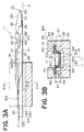
- the height position of the guide gaps 163 constituting the guide positions for the first rapier guide 16A is set to be higher than the height position of the guide edges 191 of the second rapier guides 19. That is, the height position of the guide gaps 163 is set to be higher than the guide position G (indicated by the dashed line in Fig. 3A) of the second rapier guides 19 formed by the row of guide edges 191.
- the delivery rapier head 11 moves linearly over the guide position G.
- the difference ⁇ 1 between the height position of the center of gravity 111 of a combination of the delivery rapier head 11 and the reinforcing recessed frame 20 and the height position of the lower surface 204 of the bottom wall 203 of the reinforcing recessed frame 20 of the rapier band 13A is substantially the same as the difference ⁇ 1 between the height position of the guide surfaces 164 of the first rapier guide 16A and the height position of the guide position G of the second rapier guides 19.
- reference symbol F1 indicates the position where the driving force transmitted from the rapier wheel 14 to the rapier band 13A in a linear state is applied.
- the driving force application position F1 affects the delivery rapier head 11 through the rapier band 13A, and the rapier band 13A and the delivery rapier head 11 travel integrally.
- the height position of the driving force application position F1 in the rapier band 13A in the linear state is adjusted to the height position of the movement route K1 by which the center of gravity 111 of the combination of the delivery rapier head 11 and the reinforcing recessed frame 20 moves as the delivery rapier head 11 moves. That is, the height position of the movement route K1 of the center of gravity 111 of the combination of the delivery rapier head 11 and the reinforcing recessed frame 20 is set to be within the range of the thickness of the rapier band 13A in the linear state.
- the height position of the guide gaps 163 constituting the guide positions in the first rapier guide 16B is set to be above the height position of the guide edges 191 of the second rapier guides 19. That is, the height position of the guide gaps 163 is set to be above the height position of the guide position G (indicated by the dashed line in Fig. 6A) of the second rapier guides 19 formed by the row of guide edges 191.
- the receiving rapier head 12 moves linearly over the guide position G.
- the difference ⁇ 1 between the height position of the center of gravity 111 of a combination of the receiving rapier head 12 and the reinforcing recessed frame 20 and the height positions of the lower surface 204 of the bottom wall 203 of the reinforcing recessed frame 20 of the rapier band 13B is substantially the same as the difference ⁇ 2 between the height position of the guide surfaces 164 of the first rapier guide 16B and the guide position G of the second rapier guides 19.
- numeral F2 indicates the position where the driving force transmitted from the rapier wheel 15 to the rapier band 13B in a linear state is applied.
- the driving force application position F2 affects the receiving rapier head 12 through the rapier band 13B, and the rapier band 13B and the receiving rapier head 12 travel integrally.
- the height position of the driving force application position F2 of the rapier band 13B in the linear state is adjusted to the height position of the movement route K2 by which the center of gravity 121 of the combination of the receiving rapier head 12 and the reinforcing recessed frame 20 moves as the receiving rapier head 12 moves. That is, the height position of the movement route K2 of the center of gravity 121 of the combination of the receiving rapier head 12 and the reinforcing recessed frame 20 is set to be within the range of the thickness of the rapier band 13B in the linear state.
- the first embodiment provides the following effects.
- the driving force application position F1, F2 in the rapier band 13A, 13B is adjusted to the height position in the vertical direction of the center of gravity 111, 121 of the combination of the rapier head 11, 12 and the reinforcing recessed frame 20.
- the driving force applied to the rapier band 13A, 13B is linearly transmitted to the center of gravity 111, 121 of the combination of the rapier head 11, 12 and the reinforcing recessed frame 20 along the linear configuration of the rapier band 13A, 13B in the linear state.
- generation of rotational moment around the center of gravity 111, 121 is restrained.
- the restraining of the generation of the rotational moment around the center of gravity 111, 121 helps to restrain vertical movement of the rapier head 11, 12. Further, the configuration of the reinforcing recessed frame 20 maintains the linear configuration of the forward end portion of the rapier band 13A, 13B, so that deflection of the forward end portion of the rapier band 13A, 13B is prevented.
- the restraining of vertical movement of the rapier head 11, 12 and the prevention of deflection of the rapier band 13A, 13B provide stability in the traveling of the rapier head 11, 12.
- the traveling of the rapier head 11, 12 is stable even in the case in which only the lower surface 204 of the reinforcing recessed frame 20 or the lower surface 212, 282 of the rapier head 11, 12 is guided.
- the reinforcing recessed frame 20 which is a reinforcing portion for maintaining the linear configuration of the forward end portion of the rapier band 13A, 13B, is bent substantially at right angles at four positions in the width direction of the rapier band 13A, 13B to be formed into a U-shape. Such a bent shape is superior in preventing deflection, and is easy to form.
- the reinforcing recessed frame 20 of this bent shape provides a simple reinforcing portion, and is of a smooth configuration involving no catching of warp.
- Fig. 8A illustrates the first half of the process of inserting the delivery rapier head 11 into the warp opening, or the latter half of the process of retracting the delivery rapier head 11 from the warp opening.
- FIG. 8B illustrates the first half of the process of inserting the receiving rapier head 12 into the warp opening, or the latter half of the process of retracting the receiving rapier head 12 from the warp opening.
- This setting of the length of the reinforcing recessed frame 20 is made in order that, during the first half of the process of inserting the rapier head 11, 12 into the warp opening and during the latter half of the process of retracting the rapier head 11, 12 from the warp opening, the end portions of the reinforcing recessed frame 20 of the rapier band 13A, 13B may undergo guiding action of the guide surface 165 of the first rapier guide 16A, 16B.
- the guiding action of the guide surface 165 of the first rapier guide 16A, 16B exerted on the reinforcing recessed frame 20 of the rapier band 13A, 13B helps to prevent rising of the reinforcing recessed frame 20.
- the reinforcing recessed frame 20 which prevents rising of the rapier head 11, 12, greatly contributes to stabilization in the traveling of the rapier head 11, 12.
- the reinforcing recessed frame 20, which is integrated with the rapier band 13A, 13B, can be easily formed by die shaping.
- the process of mounting a reinforcing portion formed as a separate component to the rapier band is a cumbersome task involving operations, such as screwing, pin connection, and adhesion.
- the reinforcing recessed frame 20 is integrated with the rapier band 13A, 13B, there is no need to carry out such cumbersome mounting process.
- connection area of the connecting portion between the rapier band and the reinforcing portion must be an appropriate one.
- a construction would be simple in which a reinforcing portion of a recessed sectional configuration is joined to a flat rapier band. In that case, however, the joint structure consisting of the rapier band and the reinforcing portion would be heavier than the rapier band including the reinforcing recessed frame 20 of this embodiment.
- the construction in which the rapier band and the reinforcing portion are integrated contributes to a reduction in the weight of the joint structure consisting of the rapier band and the reinforcing portion. This reduction in weight is advantageous in achieving an increase in loom speed.
- the rear half 232 of the lower wall 23 of the delivery rapier head 11C is lower than the front half 233 of the lower wall 23.
- the rear half 232 of the lower wall 23 is secured to the bottom wall 203 of the reinforcing recessed frame 20 of the rapier band 13A.
- the difference ⁇ 2 between the height position of the center of gravity 111 of the delivery rapier head 11C and the height position of the lower surface 204 of the bottom wall 203 of the reinforcing recessed frame 20 of the rapier band 13A is larger than the difference ⁇ 1 in the first embodiment.
- the rear half 302 of the lower wall 30 of the receiving rapier head 12C is lower than the front half 303 of the lower wall 30.
- the rear half 302 of the lower wall 30 is secured to the bottom wall 203 of the reinforcing recessed frame 20 of the rapier band 13B.
- the difference ⁇ 2 between the height position of the center of gravity 121 of the receiving rapier head 12C and the height position of the lower surface 204 of the bottom wall 203 of the reinforcing recessed frame 20 of the rapier band 13B is larger than the difference ⁇ 1 in the first embodiment.
- the second embodiment provides the same effect as the first embodiment. Since the height position of the lower surface 204 of the bottom wall 203 of the reinforcing recessed frame 20 is lower than in the first embodiment, the height position of the guide edges 191 of the second rapier guides 19 is also lower. Thus, the interruption amount (the amount of protrusion from the lower to the higher warp) of the guide edges 191 when the second rapier guides 19 of the second embodiment enter the warp opening is less than in the first embodiment. The less the interruption amount of the guide edges 191, the less the possibility of warp breakage and wale streak occurring.
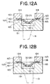
- a reinforcing portion 33 integrally formed at the forward end of the rapier band 13A, 13B may have a sectional configuration as shown in Figs. 12A and 12B.
- the joining of the rapier head 11, 12 to the reinforcing portion 33 can be easily effected by matching the configuration of the lower wall 23, 30 of the rapier head 11, 12 to the configuration of the upper surface of the reinforcing portion 33.
- the second rapier guides 19 guide the lower surface of the rapier head 11, 12, and the lower surface of the reinforcing portion 33 is not guided by the second rapier guides 19 in sliding contact therewith.
- a reinforcing portion 34 integrally formed at the forward end of the rapier band 13A, 13B may have a sectional configuration as shown in Figs. 13A and 13B.
- the joining of the rapier head 11, 12 to the reinforcing portion 34 can be easily effected by matching the configuration of the lower wall 23, 30 of the rapier head 11, 12 to the configuration of the upper surface of the reinforcing portion 34.
- the second rapier guides 19 guide the lower surface of the rapier head 11, 12, and the lower surface of the reinforcing portion 34 is not guided by the second rapier guides 19 in sliding contact therewith.
- a reinforcing portion 35 integrally formed at the forward end of the rapier band 13A, 13B may have a sectional configuration as shown in Figs. 14A and 14B.
- the reinforcing portion 35 is formed as a protruding frame having a reverse-U-shaped sectional configuration such that it protrudes upwardly beyond the upper surface of the rapier band 13A, 13B.
- the connection of the rapier head 11, 12 to the reinforcing portion 35 can be easily effected by matching the configurations of the lower wall 23, 30 of the rapier head 11, 12 to the configuration of the lower surface of the reinforcing portion.
- the second rapier guides 19 guide the lower surface of the rapier head 11, 12, and the lower surface of the reinforcing portion 35 is not guided by the second rapier guides 19 in sliding contact therewith.
- a weft insertion apparatus for a rapier loom according to a sixth embodiment of the present invention will be described with reference to Figs. 15A and 15B.
- the components, which are the same as those of the first embodiment, are indicated by the same reference symbols.
- the first rapier guide 16C is formed by joining a constraining member 162C from above to a supporting member 161C.
- Guide gaps 163C are formed between the supporting member 161C and the constraining member 162C.
- Guide surfaces 165C constituting the lower surfaces of the constraining member 162C forming the guide gaps 163C guide the widthwise end portions of the upper surface 131 of the rapier band 13A.
- a guide surface 164C constituting the upper surface of the supporting member 161C forming the guide gaps 163C guides the lower surface 204 of the bottom wall 203 of the reinforcing recessed frame 20 of the rapier band 13A or the lower surface of the lower wall 23 of the rapier head.
- a first rapier guide 16D has the same construction as the first rapier guide 16C.
- Guide surfaces 165C guide the widthwise end portions of the upper surface 131 of the rapier band 13B.
- a guide surface 164C guides the lower surface 204 of the bottom wall 203 of the reinforcing recessed frame 20 of the rapier band 13B or the lower surface of the lower wall 23 of the rapier head.
- the first rapier guides 16C and 16D outside the warp opening guide the upper surface of the upper and lower surfaces of the rapier band 13A, 13B and the lower surface 204 of the reinforcing recessed frame 20 or the lower surface of the lower wall 23 of the rapier head.
- this embodiment provides the same effect as the first embodiment.
- a weft insertion apparatus in which it is possible to achieve an improvement in the traveling stability of the rapier head even in a construction which adopts a guide guiding the rapier head or the rapier band only underneath the same inside the warp opening.
- the height position of guide position (163) in a first rapier guide (16A) outside the warp opening is set to be above the height position of guide edges (191) of second rapier guides (19) inside the warp opening.
- a delivery rapier head (11) linearly moves on the guide edges (191).
- the first rapier guide (16A) guides the widthwise end portions of a rapier band (13A), and the second rapier guides (19) guide the lower surface (204) of a reinforcing recessed frame (20) formed in the forward end portion of the rapier band (13A).
Landscapes
- Engineering & Computer Science (AREA)
- Textile Engineering (AREA)
- Looms (AREA)
Applications Claiming Priority (2)
| Application Number | Priority Date | Filing Date | Title |
|---|---|---|---|
| JP2000311866A JP4595187B2 (ja) | 2000-10-12 | 2000-10-12 | レピア織機における緯入れ装置 |
| JP2000311866 | 2000-10-12 |
Publications (3)
| Publication Number | Publication Date |
|---|---|
| EP1209267A2 true EP1209267A2 (fr) | 2002-05-29 |
| EP1209267A3 EP1209267A3 (fr) | 2003-05-02 |
| EP1209267B1 EP1209267B1 (fr) | 2006-07-26 |
Family
ID=18791564
Family Applications (1)
| Application Number | Title | Priority Date | Filing Date |
|---|---|---|---|
| EP01124172A Expired - Lifetime EP1209267B1 (fr) | 2000-10-12 | 2001-10-10 | Dispositif d'insertion de la trame pour métier à tisser à griffes |
Country Status (6)
| Country | Link |
|---|---|
| EP (1) | EP1209267B1 (fr) |
| JP (1) | JP4595187B2 (fr) |
| KR (1) | KR100428824B1 (fr) |
| CN (1) | CN1287025C (fr) |
| DE (1) | DE60121702T2 (fr) |
| TW (1) | TW508384B (fr) |
Cited By (4)
| Publication number | Priority date | Publication date | Assignee | Title |
|---|---|---|---|---|
| EP1688521A1 (fr) * | 2005-02-07 | 2006-08-09 | Officina Meccanica Trinca Colonel Silvio & Figlio Sergio S.n.c. | Dispositif pour enclencher la bande de support de pince pour insérer le fil de trame dans des machines pour faire du tissu |
| EP1749912A1 (fr) * | 2005-08-05 | 2007-02-07 | Smit S.p.A. - Unipersonale | Tête de ruban pour métier à tisser à griffes et procédé pour sa réalisation |
| BE1022753B1 (nl) * | 2015-02-02 | 2016-08-30 | Picanol | Lans, grijperweefmachine en werkwijze voor het vervaardigen van een lans |
| CN109322045A (zh) * | 2018-11-09 | 2019-02-12 | 江苏理工学院 | 一种剑杆织机的送纬装置及引纬装置 |
Families Citing this family (4)
| Publication number | Priority date | Publication date | Assignee | Title |
|---|---|---|---|---|
| CN105113107A (zh) * | 2015-09-14 | 2015-12-02 | 广西华虹绸缎有限责任公司 | 剑杆织机的浮动式导钩机构 |
| CN106637602B (zh) * | 2016-12-06 | 2018-02-27 | 中材科技股份有限公司 | 一种多层三维预成型体非对称双向剑杆引纬装置及其引纬方法 |
| CN109457370A (zh) * | 2018-09-21 | 2019-03-12 | 航宸石家庄新材料科技有限公司 | 一种储纬式双剑杆薄片带状丝束碳纤维编织机 |
| KR102562449B1 (ko) * | 2021-12-13 | 2023-08-02 | 일성기계공업 주식회사 | 위사 운반용 캐리어 |
Family Cites Families (11)
| Publication number | Priority date | Publication date | Assignee | Title |
|---|---|---|---|---|
| JPH0222387U (fr) * | 1988-07-28 | 1990-02-14 | ||
| US5176185A (en) * | 1990-07-24 | 1993-01-05 | Sulzer Brothers Limited | Guide teeth for a rapier picking tape |
| JPH0527070U (ja) * | 1991-09-17 | 1993-04-06 | 津田駒工業株式会社 | レピアヘツド |
| DE59309766D1 (de) * | 1992-07-03 | 1999-10-14 | Picanol Nv | Greiferwebmaschine |
| BE1007003A3 (nl) * | 1993-04-15 | 1995-02-14 | Picanol Nv | Weefmachine voorzien van een lans en geleidingsmiddelen. |
| JPH06299440A (ja) * | 1993-04-13 | 1994-10-25 | Ishikawa Seisakusho Ltd | レピア織機の緯糸搬送体と緯糸搬送体案内ガイド |
| IT1271130B (it) * | 1994-11-30 | 1997-05-26 | Vamatex Nuova Spa | Mezzi per guidare il moto di una coppia di pinze all'interno del passo di telai di tessitura |
| JPH1136160A (ja) * | 1997-07-16 | 1999-02-09 | Toyota Autom Loom Works Ltd | レピア織機における緯入れ装置 |
| JPH1136158A (ja) * | 1997-07-17 | 1999-02-09 | Toyota Autom Loom Works Ltd | レピア織機における緯入れ装置 |
| JPH11100749A (ja) * | 1997-09-22 | 1999-04-13 | Tsudakoma Corp | レピア織機におけるレピアバンドのガイド装置 |
| JP2000234241A (ja) * | 1999-02-15 | 2000-08-29 | Tsudakoma Corp | レピア織機におけるレピアヘッド |
-
2000
- 2000-10-12 JP JP2000311866A patent/JP4595187B2/ja not_active Expired - Fee Related
-
2001
- 2001-09-07 TW TW090122221A patent/TW508384B/zh not_active IP Right Cessation
- 2001-09-20 KR KR10-2001-0058286A patent/KR100428824B1/ko not_active Expired - Fee Related
- 2001-10-10 EP EP01124172A patent/EP1209267B1/fr not_active Expired - Lifetime
- 2001-10-10 DE DE60121702T patent/DE60121702T2/de not_active Expired - Lifetime
- 2001-10-12 CN CNB011431504A patent/CN1287025C/zh not_active Expired - Fee Related
Cited By (5)
| Publication number | Priority date | Publication date | Assignee | Title |
|---|---|---|---|---|
| EP1688521A1 (fr) * | 2005-02-07 | 2006-08-09 | Officina Meccanica Trinca Colonel Silvio & Figlio Sergio S.n.c. | Dispositif pour enclencher la bande de support de pince pour insérer le fil de trame dans des machines pour faire du tissu |
| EP1749912A1 (fr) * | 2005-08-05 | 2007-02-07 | Smit S.p.A. - Unipersonale | Tête de ruban pour métier à tisser à griffes et procédé pour sa réalisation |
| BE1022753B1 (nl) * | 2015-02-02 | 2016-08-30 | Picanol | Lans, grijperweefmachine en werkwijze voor het vervaardigen van een lans |
| CN109322045A (zh) * | 2018-11-09 | 2019-02-12 | 江苏理工学院 | 一种剑杆织机的送纬装置及引纬装置 |
| CN109322045B (zh) * | 2018-11-09 | 2024-02-23 | 江苏理工学院 | 一种剑杆织机的送纬装置及引纬装置 |
Also Published As
| Publication number | Publication date |
|---|---|
| DE60121702T2 (de) | 2007-08-02 |
| JP2002115152A (ja) | 2002-04-19 |
| JP4595187B2 (ja) | 2010-12-08 |
| EP1209267B1 (fr) | 2006-07-26 |
| CN1349009A (zh) | 2002-05-15 |
| KR100428824B1 (ko) | 2004-04-29 |
| EP1209267A3 (fr) | 2003-05-02 |
| DE60121702D1 (de) | 2006-09-07 |
| TW508384B (en) | 2002-11-01 |
| CN1287025C (zh) | 2006-11-29 |
| KR20020029298A (ko) | 2002-04-18 |
Similar Documents
| Publication | Publication Date | Title |
|---|---|---|
| JPS63165555A (ja) | 織機の杼口内における横糸支持グリッパの運動案内装置 | |
| EP1209267B1 (fr) | Dispositif d'insertion de la trame pour métier à tisser à griffes | |
| US5413151A (en) | Gripper loom rapier guide arrangement | |
| US5129431A (en) | Giver for a gripper loom | |
| CN1705778A (zh) | 片梭织机的给料片梭 | |
| US5348057A (en) | Taker gripper in which the wedge moves axially within the hook | |
| JP3796268B2 (ja) | グリッパ式織機 | |
| US4062382A (en) | Extending carrier for looms with removal of the filling yarn from stationary bobbins | |
| JPH1136159A (ja) | レピア織機における緯入れ装置 | |
| JP2002146648A (ja) | レピア織機における緯入れ装置 | |
| KR100514171B1 (ko) | 제직용 바디 | |
| EP0665909A1 (fr) | Systeme de transfert pour metiers a tisser | |
| KR102047438B1 (ko) | 위사인출 그립퍼 | |
| US4235261A (en) | Pair of grippers for weaving looms without shuttle | |
| EP1394302B1 (fr) | Améliorations de pinces-trames pour métiers à tisser et de métiers à tisser avec de moyens de guidage pour celles-ci | |
| ITMI942426A1 (it) | Mezzi per guidare il moto di una coppia di pinze all'interno del passo di telai di tessitura | |
| CN220643395U (zh) | 一种减震式片梭纱夹 | |
| US4611637A (en) | Reed for looms | |
| JP2002146649A (ja) | レピア織機における緯入れ装置 | |
| CN214089063U (zh) | 一种洗衣机悬挂弹簧及其安装结构 | |
| JPS6011116Y2 (ja) | 筬装置 | |
| JPH1053936A (ja) | レピア織機の糸クランプの搬送体及び搬送体を有するグリッパ | |
| JP2001348759A (ja) | レピア織機の緯入れ装置 | |
| BE1013013A3 (nl) | Grijperband voor een grijperweefmachine. | |
| JPH08232138A (ja) | レピアバンドのガイドユニット |
Legal Events
| Date | Code | Title | Description |
|---|---|---|---|
| PUAI | Public reference made under article 153(3) epc to a published international application that has entered the european phase |
Free format text: ORIGINAL CODE: 0009012 |
|
| 17P | Request for examination filed |
Effective date: 20011010 |
|
| AK | Designated contracting states |
Kind code of ref document: A2 Designated state(s): AT BE CH CY DE DK ES FI FR GB GR IE IT LI LU MC NL PT SE TR |
|
| AX | Request for extension of the european patent |
Free format text: AL;LT;LV;MK;RO;SI |
|
| PUAL | Search report despatched |
Free format text: ORIGINAL CODE: 0009013 |
|
| AK | Designated contracting states |
Designated state(s): AT BE CH CY DE DK ES FI FR GB GR IE IT LI LU MC NL PT SE TR |
|
| AX | Request for extension of the european patent |
Extension state: AL LT LV MK RO SI |
|
| AKX | Designation fees paid |
Designated state(s): BE DE IT |
|
| 17Q | First examination report despatched |
Effective date: 20040816 |
|
| GRAP | Despatch of communication of intention to grant a patent |
Free format text: ORIGINAL CODE: EPIDOSNIGR1 |
|
| GRAS | Grant fee paid |
Free format text: ORIGINAL CODE: EPIDOSNIGR3 |
|
| GRAA | (expected) grant |
Free format text: ORIGINAL CODE: 0009210 |
|
| AK | Designated contracting states |
Kind code of ref document: B1 Designated state(s): BE DE IT |
|
| PG25 | Lapsed in a contracting state [announced via postgrant information from national office to epo] |
Ref country code: IT Free format text: LAPSE BECAUSE OF FAILURE TO SUBMIT A TRANSLATION OF THE DESCRIPTION OR TO PAY THE FEE WITHIN THE PRESCRIBED TIME-LIMIT;WARNING: LAPSES OF ITALIAN PATENTS WITH EFFECTIVE DATE BEFORE 2007 MAY HAVE OCCURRED AT ANY TIME BEFORE 2007. THE CORRECT EFFECTIVE DATE MAY BE DIFFERENT FROM THE ONE RECORDED. Effective date: 20060726 |
|
| REF | Corresponds to: |
Ref document number: 60121702 Country of ref document: DE Date of ref document: 20060907 Kind code of ref document: P |
|
| PLBE | No opposition filed within time limit |
Free format text: ORIGINAL CODE: 0009261 |
|
| STAA | Information on the status of an ep patent application or granted ep patent |
Free format text: STATUS: NO OPPOSITION FILED WITHIN TIME LIMIT |
|
| 26N | No opposition filed |
Effective date: 20070427 |
|
| REG | Reference to a national code |
Ref country code: DE Ref legal event code: R084 Ref document number: 60121702 Country of ref document: DE Effective date: 20130606 Ref country code: DE Ref legal event code: R084 Ref document number: 60121702 Country of ref document: DE Effective date: 20130521 |
|
| PGFP | Annual fee paid to national office [announced via postgrant information from national office to epo] |
Ref country code: DE Payment date: 20131002 Year of fee payment: 13 Ref country code: BE Payment date: 20131014 Year of fee payment: 13 |
|
| PGFP | Annual fee paid to national office [announced via postgrant information from national office to epo] |
Ref country code: IT Payment date: 20131011 Year of fee payment: 13 |
|
| REG | Reference to a national code |
Ref country code: DE Ref legal event code: R119 Ref document number: 60121702 Country of ref document: DE |
|
| PG25 | Lapsed in a contracting state [announced via postgrant information from national office to epo] |
Ref country code: BE Free format text: LAPSE BECAUSE OF NON-PAYMENT OF DUE FEES Effective date: 20141031 |
|
| PG25 | Lapsed in a contracting state [announced via postgrant information from national office to epo] |
Ref country code: DE Free format text: LAPSE BECAUSE OF NON-PAYMENT OF DUE FEES Effective date: 20150501 |
|
| PG25 | Lapsed in a contracting state [announced via postgrant information from national office to epo] |
Ref country code: IT Free format text: LAPSE BECAUSE OF NON-PAYMENT OF DUE FEES Effective date: 20141010 |