EP1209330A1 - Rohrförmige Vorrichtung zur Abscheidung und Verbrennung von Russteilchen in Abgasströmen, insbesondere Dieselruss, und Verfahren zum Entfernen von Russteilchen in Abgasströmen, insbesondere Dieselabgasen - Google Patents
Rohrförmige Vorrichtung zur Abscheidung und Verbrennung von Russteilchen in Abgasströmen, insbesondere Dieselruss, und Verfahren zum Entfernen von Russteilchen in Abgasströmen, insbesondere Dieselabgasen Download PDFInfo
- Publication number
- EP1209330A1 EP1209330A1 EP01127830A EP01127830A EP1209330A1 EP 1209330 A1 EP1209330 A1 EP 1209330A1 EP 01127830 A EP01127830 A EP 01127830A EP 01127830 A EP01127830 A EP 01127830A EP 1209330 A1 EP1209330 A1 EP 1209330A1
- Authority
- EP
- European Patent Office
- Prior art keywords
- filter
- exhaust gas
- soot particles
- soot
- catalyst
- Prior art date
- Legal status (The legal status is an assumption and is not a legal conclusion. Google has not performed a legal analysis and makes no representation as to the accuracy of the status listed.)
- Granted
Links
Images

Classifications
-
- F—MECHANICAL ENGINEERING; LIGHTING; HEATING; WEAPONS; BLASTING
- F01—MACHINES OR ENGINES IN GENERAL; ENGINE PLANTS IN GENERAL; STEAM ENGINES
- F01N—GAS-FLOW SILENCERS OR EXHAUST APPARATUS FOR MACHINES OR ENGINES IN GENERAL; GAS-FLOW SILENCERS OR EXHAUST APPARATUS FOR INTERNAL-COMBUSTION ENGINES
- F01N3/00—Exhaust or silencing apparatus having means for purifying, rendering innocuous, or otherwise treating exhaust
- F01N3/02—Exhaust or silencing apparatus having means for purifying, rendering innocuous, or otherwise treating exhaust for cooling, or for removing solid constituents of, exhaust
- F01N3/021—Exhaust or silencing apparatus having means for purifying, rendering innocuous, or otherwise treating exhaust for cooling, or for removing solid constituents of, exhaust by means of filters
- F01N3/0217—Exhaust or silencing apparatus having means for purifying, rendering innocuous, or otherwise treating exhaust for cooling, or for removing solid constituents of, exhaust by means of filters the filtering elements having the form of hollow cylindrical bodies
-
- F—MECHANICAL ENGINEERING; LIGHTING; HEATING; WEAPONS; BLASTING
- F01—MACHINES OR ENGINES IN GENERAL; ENGINE PLANTS IN GENERAL; STEAM ENGINES
- F01N—GAS-FLOW SILENCERS OR EXHAUST APPARATUS FOR MACHINES OR ENGINES IN GENERAL; GAS-FLOW SILENCERS OR EXHAUST APPARATUS FOR INTERNAL-COMBUSTION ENGINES
- F01N13/00—Exhaust or silencing apparatus characterised by constructional features
- F01N13/009—Exhaust or silencing apparatus characterised by constructional features having two or more separate purifying devices arranged in series
- F01N13/0097—Exhaust or silencing apparatus characterised by constructional features having two or more separate purifying devices arranged in series the purifying devices are arranged in a single housing
-
- F—MECHANICAL ENGINEERING; LIGHTING; HEATING; WEAPONS; BLASTING
- F01—MACHINES OR ENGINES IN GENERAL; ENGINE PLANTS IN GENERAL; STEAM ENGINES
- F01N—GAS-FLOW SILENCERS OR EXHAUST APPARATUS FOR MACHINES OR ENGINES IN GENERAL; GAS-FLOW SILENCERS OR EXHAUST APPARATUS FOR INTERNAL-COMBUSTION ENGINES
- F01N3/00—Exhaust or silencing apparatus having means for purifying, rendering innocuous, or otherwise treating exhaust
- F01N3/02—Exhaust or silencing apparatus having means for purifying, rendering innocuous, or otherwise treating exhaust for cooling, or for removing solid constituents of, exhaust
- F01N3/021—Exhaust or silencing apparatus having means for purifying, rendering innocuous, or otherwise treating exhaust for cooling, or for removing solid constituents of, exhaust by means of filters
- F01N3/0212—Exhaust or silencing apparatus having means for purifying, rendering innocuous, or otherwise treating exhaust for cooling, or for removing solid constituents of, exhaust by means of filters with one or more perforated tubes surrounded by filtering material, e.g. filter candles
-
- F—MECHANICAL ENGINEERING; LIGHTING; HEATING; WEAPONS; BLASTING
- F01—MACHINES OR ENGINES IN GENERAL; ENGINE PLANTS IN GENERAL; STEAM ENGINES
- F01N—GAS-FLOW SILENCERS OR EXHAUST APPARATUS FOR MACHINES OR ENGINES IN GENERAL; GAS-FLOW SILENCERS OR EXHAUST APPARATUS FOR INTERNAL-COMBUSTION ENGINES
- F01N3/00—Exhaust or silencing apparatus having means for purifying, rendering innocuous, or otherwise treating exhaust
- F01N3/02—Exhaust or silencing apparatus having means for purifying, rendering innocuous, or otherwise treating exhaust for cooling, or for removing solid constituents of, exhaust
- F01N3/021—Exhaust or silencing apparatus having means for purifying, rendering innocuous, or otherwise treating exhaust for cooling, or for removing solid constituents of, exhaust by means of filters
- F01N3/022—Exhaust or silencing apparatus having means for purifying, rendering innocuous, or otherwise treating exhaust for cooling, or for removing solid constituents of, exhaust by means of filters characterised by specially adapted filtering structure, e.g. honeycomb, mesh or fibrous
- F01N3/0226—Exhaust or silencing apparatus having means for purifying, rendering innocuous, or otherwise treating exhaust for cooling, or for removing solid constituents of, exhaust by means of filters characterised by specially adapted filtering structure, e.g. honeycomb, mesh or fibrous the structure being fibrous
-
- F—MECHANICAL ENGINEERING; LIGHTING; HEATING; WEAPONS; BLASTING
- F01—MACHINES OR ENGINES IN GENERAL; ENGINE PLANTS IN GENERAL; STEAM ENGINES
- F01N—GAS-FLOW SILENCERS OR EXHAUST APPARATUS FOR MACHINES OR ENGINES IN GENERAL; GAS-FLOW SILENCERS OR EXHAUST APPARATUS FOR INTERNAL-COMBUSTION ENGINES
- F01N3/00—Exhaust or silencing apparatus having means for purifying, rendering innocuous, or otherwise treating exhaust
- F01N3/02—Exhaust or silencing apparatus having means for purifying, rendering innocuous, or otherwise treating exhaust for cooling, or for removing solid constituents of, exhaust
- F01N3/021—Exhaust or silencing apparatus having means for purifying, rendering innocuous, or otherwise treating exhaust for cooling, or for removing solid constituents of, exhaust by means of filters
- F01N3/033—Exhaust or silencing apparatus having means for purifying, rendering innocuous, or otherwise treating exhaust for cooling, or for removing solid constituents of, exhaust by means of filters in combination with other devices
- F01N3/035—Exhaust or silencing apparatus having means for purifying, rendering innocuous, or otherwise treating exhaust for cooling, or for removing solid constituents of, exhaust by means of filters in combination with other devices with catalytic reactors
-
- F—MECHANICAL ENGINEERING; LIGHTING; HEATING; WEAPONS; BLASTING
- F01—MACHINES OR ENGINES IN GENERAL; ENGINE PLANTS IN GENERAL; STEAM ENGINES
- F01N—GAS-FLOW SILENCERS OR EXHAUST APPARATUS FOR MACHINES OR ENGINES IN GENERAL; GAS-FLOW SILENCERS OR EXHAUST APPARATUS FOR INTERNAL-COMBUSTION ENGINES
- F01N2330/00—Structure of catalyst support or particle filter
- F01N2330/10—Fibrous material, e.g. mineral or metallic wool
-
- F—MECHANICAL ENGINEERING; LIGHTING; HEATING; WEAPONS; BLASTING
- F01—MACHINES OR ENGINES IN GENERAL; ENGINE PLANTS IN GENERAL; STEAM ENGINES
- F01N—GAS-FLOW SILENCERS OR EXHAUST APPARATUS FOR MACHINES OR ENGINES IN GENERAL; GAS-FLOW SILENCERS OR EXHAUST APPARATUS FOR INTERNAL-COMBUSTION ENGINES
- F01N2330/00—Structure of catalyst support or particle filter
- F01N2330/12—Metallic wire mesh fabric or knitting
-
- F—MECHANICAL ENGINEERING; LIGHTING; HEATING; WEAPONS; BLASTING
- F01—MACHINES OR ENGINES IN GENERAL; ENGINE PLANTS IN GENERAL; STEAM ENGINES
- F01N—GAS-FLOW SILENCERS OR EXHAUST APPARATUS FOR MACHINES OR ENGINES IN GENERAL; GAS-FLOW SILENCERS OR EXHAUST APPARATUS FOR INTERNAL-COMBUSTION ENGINES
- F01N2330/00—Structure of catalyst support or particle filter
- F01N2330/14—Sintered material
-
- F—MECHANICAL ENGINEERING; LIGHTING; HEATING; WEAPONS; BLASTING
- F01—MACHINES OR ENGINES IN GENERAL; ENGINE PLANTS IN GENERAL; STEAM ENGINES
- F01N—GAS-FLOW SILENCERS OR EXHAUST APPARATUS FOR MACHINES OR ENGINES IN GENERAL; GAS-FLOW SILENCERS OR EXHAUST APPARATUS FOR INTERNAL-COMBUSTION ENGINES
- F01N2510/00—Surface coverings
- F01N2510/06—Surface coverings for exhaust purification, e.g. catalytic reaction
- F01N2510/065—Surface coverings for exhaust purification, e.g. catalytic reaction for reducing soot ignition temperature
-
- F—MECHANICAL ENGINEERING; LIGHTING; HEATING; WEAPONS; BLASTING
- F01—MACHINES OR ENGINES IN GENERAL; ENGINE PLANTS IN GENERAL; STEAM ENGINES
- F01N—GAS-FLOW SILENCERS OR EXHAUST APPARATUS FOR MACHINES OR ENGINES IN GENERAL; GAS-FLOW SILENCERS OR EXHAUST APPARATUS FOR INTERNAL-COMBUSTION ENGINES
- F01N3/00—Exhaust or silencing apparatus having means for purifying, rendering innocuous, or otherwise treating exhaust
- F01N3/02—Exhaust or silencing apparatus having means for purifying, rendering innocuous, or otherwise treating exhaust for cooling, or for removing solid constituents of, exhaust
- F01N3/021—Exhaust or silencing apparatus having means for purifying, rendering innocuous, or otherwise treating exhaust for cooling, or for removing solid constituents of, exhaust by means of filters
- F01N3/023—Exhaust or silencing apparatus having means for purifying, rendering innocuous, or otherwise treating exhaust for cooling, or for removing solid constituents of, exhaust by means of filters using means for regenerating the filters, e.g. by burning trapped particles
Definitions
- the invention relates to a tubular device for the separation and combustion of Soot particles in exhaust gas streams, in particular diesel soot, with a catalyst and a filter, and a method for removing soot particles in exhaust gas streams, in particular diesel exhaust gases, by means of a tubular device, the soot particles being deposited on a filter are.
- the NO-containing exhaust gas is first passed without a filter over a catalytic converter in order to convert the NO in the exhaust gas to NO 2 , before filtering to remove it particles.
- the N0 2 containing exhaust gas is then used to burn the trapped on the filter particles, wherein the amount of converted to NO 2 NO sufficient to enable it to continue the combustion of the trapped on the filter particles at a temperature of less than 400 ° C ,
- the associated device disclosed therein initially consists of a tubular device in which the above-mentioned catalyst for converting NO to NO 2 is located, after which a second tubular body has the above-mentioned filter for depositing the diesel soot.
- a disadvantage of this method and this device is the fact that one is not always satisfactory interaction in terms of efficiency between catalyst and filter can occur and in connection with this the ratio of the volume consumed to Effectiveness of the device, especially when applied to passenger cars, is unfavorable appears.
- practice shows that only sulfur-free diesel fuel is used may be.
- this problem is solved by a device according to claim 1 A method according to claim 5 and solved by a use according to claim 9.
- a catalyst for lowering is on a first filter the soot ignition point temperature applied as a coating, with a second filter first filter in the longitudinal direction of the tubular device and / or radially at least partially encloses.
- the exhaust gas containing soot particles is passed through the first filter, the soot particles are separated on the first filter and the second filter, at the same time the exhaust gas on the first filter is conditioned with the aid of the catalytic converter in order to burn of the soot particles deposited on the first and second filters.
- the device according to the invention is thus designed as a so-called filter candle.
- the spatial Fixing and spacing of the first and second filters from one another takes place in the Usually through radial perforated plates.
- the first filter can be provided with a catalytic aluminum oxide-containing coating be, which are also inorganic oxides of rare earth metals and / or La, Ti, Zr, Hf and others May contain metals.
- the coating can be precious metals, for example, as active components Pt, Pd, Rh, Ru or Ir included.
- the second filter contains a further substance that lowers the soot ignition point, for example Fe, Cu, Mo, La, Cs, V, Ce, Zr, Si as oxides or mixed oxides and / or with the catalyst conditioning the exhaust gas, for example Pt, Pd, Ru, Rh; Ir or combinations of this, is coated, since in the first case the combustion of those deposited on the second filter Soot particles relieved and in the second case by the one fixed on the second filter A catalyst redundancy is available.
- a further substance that lowers the soot ignition point for example Fe, Cu, Mo, La, Cs, V, Ce, Zr, Si as oxides or mixed oxides and / or with the catalyst conditioning the exhaust gas, for example Pt, Pd, Ru, Rh; Ir or combinations of this, is coated, since in the first case the combustion of those deposited on the second filter Soot particles relieved and in the second case by the one fixed on the second filter A catalyst redundancy is available.
- the first filter is a wire mesh filter and / or the second Filters made of a ceramic or metallic knitted fabric, fabric, flow, fiber or sintered body exists because these embodiments have proven themselves in practice.
- exhaust gas containing soot particles is passed through a first with a filter coated to reduce the soot ignition temperature and the soot particles are separated on the first and on a second filter and simultaneously with the help of the catalytic converter, the exhaust gas for burning those separated on the first and second filters Soot particles conditioned, the second filter the first filter lengthways and / or at least partially radially.
- the second filter contains a further substance that lowers the ignition point and / or is coated with the exhaust gas conditioning catalyst, since in the first case the burning of the soot particles separated on the second filter is facilitated and in the second If the catalyst is fixed to the second filter, conditioning redundancy is available stands.
- the first filter is a wire mesh filter and / or the second Filters made of a ceramic or metallic knitted fabric, fabric, flow, fiber or sintered body exists because these embodiments have proven themselves in practice.
- the device according to the invention is primarily used to remove soot particles in exhaust gas streams, especially diesel exhaust. Surprisingly, it has been shown that the The device according to the invention also works with sulfur-containing diesel exhaust gases the combustion of fuel with a maximum concentration of 500 ppm sulfur.
- Figure 1 is a sketch of a tubular device according to the invention for removing Soot particles shown in exhaust gas streams.
- the device according to the invention essentially consists of one in the longitudinal direction extending center axis tubular inner first wire mesh filter 1, the has a catalytic coating to lower the soot ignition point temperature.
- This first filter 1 is by means of a tubular perforated plate 3 from an adjacent and the first filter 1 in the longitudinal direction and radially enclosing second filter 2.
- the second filter 2 is in turn radially surrounded by another perforated plate 3 in the longitudinal direction.
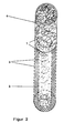
- FIG. 2 shows a sketch of another tubular device for removal according to the invention represented by soot particles in exhaust gas streams.
- the device according to the invention essentially consists of one in the longitudinal direction extending center axis tubular inner first wire mesh filter 1, the has a catalytic coating to lower the soot ignition point temperature.
- the first filter is by means of a tubular perforated plate 3 from an adjacent one and the first filter 1 partially in the longitudinal direction and completely radially enclosing second filter 2 spaced.
- the second filter 2 is in turn from another perforated plate 3 in the longitudinal direction surrounded radially.
- the first to flow through is a filter with a wire mesh filter 1 filled tubular jacket 4. This special design shows unexpectedly high burn rates the soot particles and a correspondingly highly efficient conditioning of the exhaust gas.
Landscapes
- Engineering & Computer Science (AREA)
- Chemical & Material Sciences (AREA)
- Combustion & Propulsion (AREA)
- Mechanical Engineering (AREA)
- General Engineering & Computer Science (AREA)
- Chemical Kinetics & Catalysis (AREA)
- Processes For Solid Components From Exhaust (AREA)
- Exhaust Gas After Treatment (AREA)
- Filtering Of Dispersed Particles In Gases (AREA)
Abstract
Description
- Figur 1
- eine skizzenhafte Darstellung einer erfindungsgemäßen rohrförmigen Vorrichtung.
- Figur 2
- eine skizzenhafte Darstellung einer weiteren erfindungsgemäßen rohrförmigen Vorrichtung.
Claims (10)
- Rohrförmige Vorrichtung zur Abscheidung und Verbrennung von Rußteilchen in Abgasströmen, insbesondere Dieselruß, mit einem Katalysator und einem Filter, dadurch gekennzeichnet, dass der Rußzündpunkttemperatur absenkende Katalysator als Beschichtung auf einem ersten Filter (1) aufgebracht ist, wobei ein zweiter Filter (2) den ersten Filter (1) in Längsrichtung und/öder radial zumindest teilweise umschließt, so dass Rußteilchen enthaltendes Abgas durch den ersten Filter (1) geführt wird, dabei die Rußteilchen am ersten Filter (1) und am zweiten Filter (2) abgeschieden werden und gleichzeitig am ersten Filter (1) das Abgas zum Verbrennen der am ersten und zweiten Filter (1, 2) abgeschiedenen Rußteilchen konditioniert wird.
- Vorrichtung nach Anspruch 1, dadurch gekennzeichnet, dass der zweite Filter (2) mit einer weiteren rußzündpunkterniedrigenden Substanz und/oder mit dem das Abgas konditionierenden Katalysator beschichtet ist.
- Vorrichtung nach einem der Ansprüche 1 bis 2, dadurch gekennzeichnet, dass der erste Filter (1) ein Drahtgestrickfilter ist.
- Vorrichtung nach einem der Ansprüche 1 bis 3, dadurch gekennzeichnet, dass der zweite Filter (2) aus einem keramischen oder metallischen Gestrick, Gewebe, Fließ, Faser- oder Sinterkörper besteht.
- Verfahren zum Entfernen von Rußteilchen in Abgasströmen, insbesondere Dieselabgasen, mittels einer rohrförmigen Vorrichtung, wobei die Rußteilchen auf einem Filter abgelagert sind, dadurch gekennzeichnet, dass Rußteilchen enthaltendes Abgas durch einen ersten mit einem die Rußzündpunkttemperatur absenkenden Katalysator beschichteten Filter (1) geführt wird, dabei die Rußteilchen am ersten und an einem zweiten Filter (1, 2) abgeschieden werden, gleichzeitig mit Hilfe des Katalysators das Abgas zum Verbrennen der am ersten und zweiten Filter (1, 2) abgeschiedenen Rußteilchen konditioniert wird, wobei der zweite Filter (2) den ersten Filter (1) in Längsrichtung radial zumindest teilweise umschließt.
- Verfahren nach Anspruch 5, dadurch gekennzeichnet, dass der zweite Filter (2) mit einer weiteren rußzündpunkterniedrigenden Substanz und/oder mit dem das Abgas konditionierenden Katalysator beschichtet ist.
- Verfahren nach einem der Ansprüche 5 bis 6, dadurch gekennzeichnet, dass der erste Filter (1) ein Drahtgestrickfilter ist.
- Verfahren nach einem der Ansprüche 5 bis 7, dadurch gekennzeichnet, dass der zweite Filter (2) aus einem Keramikgestrick, Keramikfließ oder aus Metallfasern besteht.
- Verwendung einer Vorrichtung nach einem der Ansprüche 1 bis 4 zum Entfernen von Rußteilchen in Abgasströmen, insbesondere Dieselabgasen.
- Verwendung nach Anspruch 9, dadurch gekennzeichnet, dass es sich bei den Abgasströmen um schwefelhaltige Dieselabgase handelt, die aus der Verbrennung von Kraftstoff mit einer Maximalkonzentration von 500 ppm Schwefel stammen.
Applications Claiming Priority (2)
| Application Number | Priority Date | Filing Date | Title |
|---|---|---|---|
| DE10058824 | 2000-11-27 | ||
| DE10058824A DE10058824A1 (de) | 2000-11-27 | 2000-11-27 | Rohrförmige Vorrichtung zur Abscheidung und Verbrennung von Rußteilchen in Abgasströmen, insbesondere Dieselruß, und Verfahren zum Entfernen von Rußteilchen in Abgasströmen, insbesondere Dieselabgasen |
Publications (2)
| Publication Number | Publication Date |
|---|---|
| EP1209330A1 true EP1209330A1 (de) | 2002-05-29 |
| EP1209330B1 EP1209330B1 (de) | 2004-09-08 |
Family
ID=7664818
Family Applications (1)
| Application Number | Title | Priority Date | Filing Date |
|---|---|---|---|
| EP01127830A Expired - Lifetime EP1209330B1 (de) | 2000-11-27 | 2001-11-22 | Rohrförmige Vorrichtung zur Abscheidung und Verbrennung von Russteilchen in Abgasströmen, insbesondere Dieselruss, und Verfahren zum Entfernen von Russteilchen in Abgasströmen, insbesondere Dieselabgasen |
Country Status (2)
| Country | Link |
|---|---|
| EP (1) | EP1209330B1 (de) |
| DE (2) | DE10058824A1 (de) |
Cited By (3)
| Publication number | Priority date | Publication date | Assignee | Title |
|---|---|---|---|---|
| WO2004015251A1 (de) * | 2002-08-02 | 2004-02-19 | Emitec Gesellschaft Für Emissionstechnologie Mbh | Abgasfilter und verfahren zum reinigen eines abgases |
| WO2008118275A1 (en) * | 2007-03-27 | 2008-10-02 | Caterpillar Inc. | Exhaust particulate filter for a machine engine system and assembly method therefor |
| US9689354B1 (en) | 2016-01-19 | 2017-06-27 | Ford Global Technologies, Llc | Engine exhaust gas recirculation system with at least one exhaust recirculation treatment device |
Families Citing this family (1)
| Publication number | Priority date | Publication date | Assignee | Title |
|---|---|---|---|---|
| DE10309862B4 (de) * | 2003-03-06 | 2006-07-13 | Rhodius Gmbh | Vorrichtung zum Entfernen von Schadstoffen aus einem Abgas einer Brennkraftmaschine, insbesondere eines Dieselmotors |
Citations (6)
| Publication number | Priority date | Publication date | Assignee | Title |
|---|---|---|---|---|
| US4600562A (en) * | 1984-12-24 | 1986-07-15 | Texaco Inc. | Method and apparatus for filtering engine exhaust gas |
| US5067319A (en) * | 1989-02-15 | 1991-11-26 | Steyr-Daimler-Puch Ag | System for purifying the exhaust gases of diesel engines |
| DE4207005A1 (de) * | 1991-03-06 | 1992-09-10 | Nissan Motor | Abgasreiniger |
| EP0341832B1 (de) | 1988-05-13 | 1996-01-10 | Johnson Matthey Inc. | Behandlung von Dieselabgas |
| EP1065352A2 (de) * | 1999-06-29 | 2001-01-03 | Sumitomo Electric Industries, Ltd. | Partikelfalle für Dieselmotor |
| DE19933442A1 (de) * | 1999-07-16 | 2001-01-18 | Mann & Hummel Filter | Partikelfilter mit einem Filtermedium und einem Katalysator |
Family Cites Families (1)
| Publication number | Priority date | Publication date | Assignee | Title |
|---|---|---|---|---|
| DE4012719A1 (de) * | 1990-04-21 | 1991-10-24 | Roggenkamp Karl Heinz | Verfahren zur beseitigung von schaedlichen bestandteilen aus abgasen von brennkraftmaschinen, insbesondere von dieselmotoren und vorrichtung zur durchfuehrung des verfahrens |
-
2000
- 2000-11-27 DE DE10058824A patent/DE10058824A1/de not_active Withdrawn
-
2001
- 2001-11-22 EP EP01127830A patent/EP1209330B1/de not_active Expired - Lifetime
- 2001-11-22 DE DE50103526T patent/DE50103526D1/de not_active Expired - Lifetime
Patent Citations (6)
| Publication number | Priority date | Publication date | Assignee | Title |
|---|---|---|---|---|
| US4600562A (en) * | 1984-12-24 | 1986-07-15 | Texaco Inc. | Method and apparatus for filtering engine exhaust gas |
| EP0341832B1 (de) | 1988-05-13 | 1996-01-10 | Johnson Matthey Inc. | Behandlung von Dieselabgas |
| US5067319A (en) * | 1989-02-15 | 1991-11-26 | Steyr-Daimler-Puch Ag | System for purifying the exhaust gases of diesel engines |
| DE4207005A1 (de) * | 1991-03-06 | 1992-09-10 | Nissan Motor | Abgasreiniger |
| EP1065352A2 (de) * | 1999-06-29 | 2001-01-03 | Sumitomo Electric Industries, Ltd. | Partikelfalle für Dieselmotor |
| DE19933442A1 (de) * | 1999-07-16 | 2001-01-18 | Mann & Hummel Filter | Partikelfilter mit einem Filtermedium und einem Katalysator |
Cited By (6)
| Publication number | Priority date | Publication date | Assignee | Title |
|---|---|---|---|---|
| WO2004015251A1 (de) * | 2002-08-02 | 2004-02-19 | Emitec Gesellschaft Für Emissionstechnologie Mbh | Abgasfilter und verfahren zum reinigen eines abgases |
| RU2316656C2 (ru) * | 2002-08-02 | 2008-02-10 | Эмитек Гезельшафт Фюр Эмиссионстехнологи Мбх | Фильтр для очистки отработавших газов и способ очистки отработавших газов |
| US7347042B2 (en) | 2002-08-02 | 2008-03-25 | Emitec Gesellschaft Fuer Emissionstechnologie Mbh | Exhaust gas filter and method for cleaning an exhaust gas |
| KR101009197B1 (ko) * | 2002-08-02 | 2011-01-19 | 에미텍 게젤샤프트 퓌어 에미시온스테크놀로기 엠베하 | 배기 가스 필터 및 배기 가스 정화 방법 |
| WO2008118275A1 (en) * | 2007-03-27 | 2008-10-02 | Caterpillar Inc. | Exhaust particulate filter for a machine engine system and assembly method therefor |
| US9689354B1 (en) | 2016-01-19 | 2017-06-27 | Ford Global Technologies, Llc | Engine exhaust gas recirculation system with at least one exhaust recirculation treatment device |
Also Published As
| Publication number | Publication date |
|---|---|
| DE10058824A1 (de) | 2002-06-13 |
| DE50103526D1 (de) | 2004-10-14 |
| EP1209330B1 (de) | 2004-09-08 |
Similar Documents
| Publication | Publication Date | Title |
|---|---|---|
| DE3232729C2 (de) | ||
| DE69902446T3 (de) | Verbesserungen der schadstoffregelung | |
| EP0077524B1 (de) | Verfahren zur Herabsetzung der Zündtemperatur von Dieselruss | |
| EP1055805B1 (de) | Verfahren und Vorrichtung zur Entfernung von Russ aus dem Abgas eines Dieselmotors | |
| DE69216101T2 (de) | Partikelfilter zur reinigung von dieselmotorabgas | |
| DE69101661T2 (de) | Katalysator zum Reinigen von Abgasen von Dieselmotoren. | |
| DE69503176T2 (de) | Dieselabgas-Partikelfilter | |
| DE68925382T2 (de) | Behandlung von Dieselabgas | |
| DE60200737T2 (de) | Vorrichtung zur Kohlenstoffpartikelreduktion | |
| EP1179125B1 (de) | Vorrichtung zum reduzieren von schädlichen bestandteilen im abgas einer brennkraftmaschine, insbesondere einer diesel-brennkraftmaschine | |
| DE69908299T2 (de) | Plasmaunterstützte gasbehandlung | |
| DE19525134C2 (de) | Vorrichtung zur Reinigung von Abgas einer gemischverdichtenden Verbrennungskraftmaschine | |
| DE2501241A1 (de) | Fluidbehandlungsstruktur | |
| DE102015212788A1 (de) | Katalytisch aktives Partikelfilter | |
| DE60212245T3 (de) | Verfahren und Vorrichtung zur Entfernung von Russpartikeln aus dem Abgas eines Dieselmotors | |
| DE69731789T2 (de) | Vorrichtung zur Reinigung der Abgasen eines Dieselmotors | |
| EP1209330B1 (de) | Rohrförmige Vorrichtung zur Abscheidung und Verbrennung von Russteilchen in Abgasströmen, insbesondere Dieselruss, und Verfahren zum Entfernen von Russteilchen in Abgasströmen, insbesondere Dieselabgasen | |
| EP0086367B1 (de) | Vorrichtung zur Reinigung der Abgase von Dieselmotoren, insbesondere bei Kraftfahrzeugen | |
| DE3541685A1 (de) | Verfahren zur reinigung von abgasen eines verbrennungsmotors | |
| DE10036401B4 (de) | Vorrichtung zum Verringern der schädlichen Bestandteile im Abgas einer Brennkraftmaschine, insbesondere einer Diesel-Brennkraftmaschine | |
| WO2013160472A1 (de) | Beschichteter partikelfilter, katalysator und einrichtung mit denselben | |
| EP2740913A1 (de) | Abgasnachbehandlungssystem | |
| EP1759097B1 (de) | Vorrichtung zur reinigung von abgasen einer verbrennungskraftmaschine | |
| DE19824285C2 (de) | Rußfilter für eine Verbrennungskraftmaschine | |
| DE10218775A1 (de) | Vorrichtung zur Reinigung von Abgasen einer Verbrennungskraftmaschine |
Legal Events
| Date | Code | Title | Description |
|---|---|---|---|
| PUAI | Public reference made under article 153(3) epc to a published international application that has entered the european phase |
Free format text: ORIGINAL CODE: 0009012 |
|
| 17P | Request for examination filed |
Effective date: 20011130 |
|
| AK | Designated contracting states |
Kind code of ref document: A1 Designated state(s): AT BE CH CY DE DK ES FI FR GB GR IE IT LI LU MC NL PT SE TR |
|
| AX | Request for extension of the european patent |
Free format text: AL;LT;LV;MK;RO;SI |
|
| AKX | Designation fees paid |
Designated state(s): CH DE FR GB IT LI NL |
|
| 17Q | First examination report despatched |
Effective date: 20030624 |
|
| GRAP | Despatch of communication of intention to grant a patent |
Free format text: ORIGINAL CODE: EPIDOSNIGR1 |
|
| GRAS | Grant fee paid |
Free format text: ORIGINAL CODE: EPIDOSNIGR3 |
|
| GRAA | (expected) grant |
Free format text: ORIGINAL CODE: 0009210 |
|
| AK | Designated contracting states |
Kind code of ref document: B1 Designated state(s): CH DE FR GB IT LI NL |
|
| REG | Reference to a national code |
Ref country code: GB Ref legal event code: FG4D Free format text: NOT ENGLISH |
|
| REG | Reference to a national code |
Ref country code: CH Ref legal event code: EP Ref country code: CH Ref legal event code: NV Representative=s name: KIRKER & CIE SA |
|
| GBT | Gb: translation of ep patent filed (gb section 77(6)(a)/1977) |
Effective date: 20040908 |
|
| REF | Corresponds to: |
Ref document number: 50103526 Country of ref document: DE Date of ref document: 20041014 Kind code of ref document: P |
|
| REG | Reference to a national code |
Ref country code: IE Ref legal event code: FD4D |
|
| PLBE | No opposition filed within time limit |
Free format text: ORIGINAL CODE: 0009261 |
|
| STAA | Information on the status of an ep patent application or granted ep patent |
Free format text: STATUS: NO OPPOSITION FILED WITHIN TIME LIMIT |
|
| RAP2 | Party data changed (patent owner data changed or rights of a patent transferred) |
Owner name: W.C. HERAEUS GMBH |
|
| ET | Fr: translation filed | ||
| 26N | No opposition filed |
Effective date: 20050609 |
|
| REG | Reference to a national code |
Ref country code: CH Ref legal event code: PFA Owner name: W.C. HERAEUS GMBH Free format text: W.C. HERAEUS GMBH & CO. KG#HERAEUSSTRASSE 12-14#63450 HANAU (DE) -TRANSFER TO- W.C. HERAEUS GMBH#HERAEUSSTRASSE 12 - 14#63450 HANAU (DE) |
|
| NLT2 | Nl: modifications (of names), taken from the european patent patent bulletin |
Owner name: W.C. HERAEUS GMBH Effective date: 20050720 |
|
| REG | Reference to a national code |
Ref country code: FR Ref legal event code: CJ |
|
| NLT1 | Nl: modifications of names registered in virtue of documents presented to the patent office pursuant to art. 16 a, paragraph 1 |
Owner name: W.C. HERAEUS GMBH |
|
| PGFP | Annual fee paid to national office [announced via postgrant information from national office to epo] |
Ref country code: CH Payment date: 20091124 Year of fee payment: 9 Ref country code: DE Payment date: 20091120 Year of fee payment: 9 |
|
| PGFP | Annual fee paid to national office [announced via postgrant information from national office to epo] |
Ref country code: NL Payment date: 20091112 Year of fee payment: 9 |
|
| PGFP | Annual fee paid to national office [announced via postgrant information from national office to epo] |
Ref country code: FR Payment date: 20091201 Year of fee payment: 9 Ref country code: GB Payment date: 20091119 Year of fee payment: 9 Ref country code: IT Payment date: 20091121 Year of fee payment: 9 |
|
| REG | Reference to a national code |
Ref country code: NL Ref legal event code: V1 Effective date: 20110601 |
|
| REG | Reference to a national code |
Ref country code: CH Ref legal event code: PL |
|
| GBPC | Gb: european patent ceased through non-payment of renewal fee |
Effective date: 20101122 |
|
| PG25 | Lapsed in a contracting state [announced via postgrant information from national office to epo] |
Ref country code: LI Free format text: LAPSE BECAUSE OF NON-PAYMENT OF DUE FEES Effective date: 20101130 Ref country code: CH Free format text: LAPSE BECAUSE OF NON-PAYMENT OF DUE FEES Effective date: 20101130 |
|
| REG | Reference to a national code |
Ref country code: DE Ref legal event code: R119 Ref document number: 50103526 Country of ref document: DE Effective date: 20110601 Ref country code: DE Ref legal event code: R119 Ref document number: 50103526 Country of ref document: DE Effective date: 20110531 |
|
| REG | Reference to a national code |
Ref country code: FR Ref legal event code: ST Effective date: 20110801 |
|
| PG25 | Lapsed in a contracting state [announced via postgrant information from national office to epo] |
Ref country code: NL Free format text: LAPSE BECAUSE OF NON-PAYMENT OF DUE FEES Effective date: 20110601 |
|
| PG25 | Lapsed in a contracting state [announced via postgrant information from national office to epo] |
Ref country code: DE Free format text: LAPSE BECAUSE OF NON-PAYMENT OF DUE FEES Effective date: 20110531 |
|
| PG25 | Lapsed in a contracting state [announced via postgrant information from national office to epo] |
Ref country code: FR Free format text: LAPSE BECAUSE OF NON-PAYMENT OF DUE FEES Effective date: 20101130 |
|
| PG25 | Lapsed in a contracting state [announced via postgrant information from national office to epo] |
Ref country code: GB Free format text: LAPSE BECAUSE OF NON-PAYMENT OF DUE FEES Effective date: 20101122 |
|
| PG25 | Lapsed in a contracting state [announced via postgrant information from national office to epo] |
Ref country code: IT Free format text: LAPSE BECAUSE OF NON-PAYMENT OF DUE FEES Effective date: 20101122 |