EP1209341B1 - Verfahren zur Steuerung eines Verbrennungsmotors zur Optimierung des Starts - Google Patents
Verfahren zur Steuerung eines Verbrennungsmotors zur Optimierung des Starts Download PDFInfo
- Publication number
- EP1209341B1 EP1209341B1 EP01403004A EP01403004A EP1209341B1 EP 1209341 B1 EP1209341 B1 EP 1209341B1 EP 01403004 A EP01403004 A EP 01403004A EP 01403004 A EP01403004 A EP 01403004A EP 1209341 B1 EP1209341 B1 EP 1209341B1
- Authority
- EP
- European Patent Office
- Prior art keywords
- valves
- cylinders
- cylinder
- carried out
- engine
- Prior art date
- Legal status (The legal status is an assumption and is not a legal conclusion. Google has not performed a legal analysis and makes no representation as to the accuracy of the status listed.)
- Expired - Lifetime
Links
Images


Classifications
-
- F—MECHANICAL ENGINEERING; LIGHTING; HEATING; WEAPONS; BLASTING
- F02—COMBUSTION ENGINES; HOT-GAS OR COMBUSTION-PRODUCT ENGINE PLANTS
- F02D—CONTROLLING COMBUSTION ENGINES
- F02D41/00—Electrical control of supply of combustible mixture or its constituents
- F02D41/0002—Controlling intake air
-
- F—MECHANICAL ENGINEERING; LIGHTING; HEATING; WEAPONS; BLASTING
- F01—MACHINES OR ENGINES IN GENERAL; ENGINE PLANTS IN GENERAL; STEAM ENGINES
- F01L—CYCLICALLY OPERATING VALVES FOR MACHINES OR ENGINES
- F01L9/00—Valve-gear or valve arrangements actuated non-mechanically
- F01L9/20—Valve-gear or valve arrangements actuated non-mechanically by electric means
-
- F—MECHANICAL ENGINEERING; LIGHTING; HEATING; WEAPONS; BLASTING
- F02—COMBUSTION ENGINES; HOT-GAS OR COMBUSTION-PRODUCT ENGINE PLANTS
- F02D—CONTROLLING COMBUSTION ENGINES
- F02D13/00—Controlling the engine output power by varying inlet or exhaust valve operating characteristics, e.g. timing
- F02D13/02—Controlling the engine output power by varying inlet or exhaust valve operating characteristics, e.g. timing during engine operation
- F02D13/0203—Variable control of intake and exhaust valves
-
- F—MECHANICAL ENGINEERING; LIGHTING; HEATING; WEAPONS; BLASTING
- F02—COMBUSTION ENGINES; HOT-GAS OR COMBUSTION-PRODUCT ENGINE PLANTS
- F02D—CONTROLLING COMBUSTION ENGINES
- F02D13/00—Controlling the engine output power by varying inlet or exhaust valve operating characteristics, e.g. timing
- F02D13/02—Controlling the engine output power by varying inlet or exhaust valve operating characteristics, e.g. timing during engine operation
- F02D13/0257—Independent control of two or more intake or exhaust valves respectively, i.e. one of two intake valves remains closed or is opened partially while the other is fully opened
-
- F—MECHANICAL ENGINEERING; LIGHTING; HEATING; WEAPONS; BLASTING
- F02—COMBUSTION ENGINES; HOT-GAS OR COMBUSTION-PRODUCT ENGINE PLANTS
- F02D—CONTROLLING COMBUSTION ENGINES
- F02D41/00—Electrical control of supply of combustible mixture or its constituents
- F02D41/02—Circuit arrangements for generating control signals
- F02D41/04—Introducing corrections for particular operating conditions
- F02D41/06—Introducing corrections for particular operating conditions for engine starting or warming up
- F02D41/062—Introducing corrections for particular operating conditions for engine starting or warming up for starting
-
- F—MECHANICAL ENGINEERING; LIGHTING; HEATING; WEAPONS; BLASTING
- F02—COMBUSTION ENGINES; HOT-GAS OR COMBUSTION-PRODUCT ENGINE PLANTS
- F02D—CONTROLLING COMBUSTION ENGINES
- F02D41/00—Electrical control of supply of combustible mixture or its constituents
- F02D41/02—Circuit arrangements for generating control signals
- F02D41/04—Introducing corrections for particular operating conditions
- F02D41/06—Introducing corrections for particular operating conditions for engine starting or warming up
- F02D41/062—Introducing corrections for particular operating conditions for engine starting or warming up for starting
- F02D41/065—Introducing corrections for particular operating conditions for engine starting or warming up for starting at hot start or restart
-
- F—MECHANICAL ENGINEERING; LIGHTING; HEATING; WEAPONS; BLASTING
- F01—MACHINES OR ENGINES IN GENERAL; ENGINE PLANTS IN GENERAL; STEAM ENGINES
- F01L—CYCLICALLY OPERATING VALVES FOR MACHINES OR ENGINES
- F01L2800/00—Methods of operation using a variable valve timing mechanism
-
- F—MECHANICAL ENGINEERING; LIGHTING; HEATING; WEAPONS; BLASTING
- F02—COMBUSTION ENGINES; HOT-GAS OR COMBUSTION-PRODUCT ENGINE PLANTS
- F02D—CONTROLLING COMBUSTION ENGINES
- F02D13/00—Controlling the engine output power by varying inlet or exhaust valve operating characteristics, e.g. timing
- F02D13/02—Controlling the engine output power by varying inlet or exhaust valve operating characteristics, e.g. timing during engine operation
- F02D13/0253—Fully variable control of valve lift and timing using camless actuation systems such as hydraulic, pneumatic or electromagnetic actuators, e.g. solenoid valves
-
- F—MECHANICAL ENGINEERING; LIGHTING; HEATING; WEAPONS; BLASTING
- F02—COMBUSTION ENGINES; HOT-GAS OR COMBUSTION-PRODUCT ENGINE PLANTS
- F02D—CONTROLLING COMBUSTION ENGINES
- F02D13/00—Controlling the engine output power by varying inlet or exhaust valve operating characteristics, e.g. timing
- F02D13/02—Controlling the engine output power by varying inlet or exhaust valve operating characteristics, e.g. timing during engine operation
- F02D13/0261—Controlling the valve overlap
- F02D13/0265—Negative valve overlap for temporarily storing residual gas in the cylinder
-
- F—MECHANICAL ENGINEERING; LIGHTING; HEATING; WEAPONS; BLASTING
- F02—COMBUSTION ENGINES; HOT-GAS OR COMBUSTION-PRODUCT ENGINE PLANTS
- F02D—CONTROLLING COMBUSTION ENGINES
- F02D2200/00—Input parameters for engine control
- F02D2200/50—Input parameters for engine control said parameters being related to the vehicle or its components
- F02D2200/503—Battery correction, i.e. corrections as a function of the state of the battery, its output or its type
-
- F—MECHANICAL ENGINEERING; LIGHTING; HEATING; WEAPONS; BLASTING
- F02—COMBUSTION ENGINES; HOT-GAS OR COMBUSTION-PRODUCT ENGINE PLANTS
- F02N—STARTING OF COMBUSTION ENGINES; STARTING AIDS FOR SUCH ENGINES, NOT OTHERWISE PROVIDED FOR
- F02N19/00—Starting aids for combustion engines, not otherwise provided for
- F02N19/004—Aiding engine start by using decompression means or variable valve actuation
-
- Y—GENERAL TAGGING OF NEW TECHNOLOGICAL DEVELOPMENTS; GENERAL TAGGING OF CROSS-SECTIONAL TECHNOLOGIES SPANNING OVER SEVERAL SECTIONS OF THE IPC; TECHNICAL SUBJECTS COVERED BY FORMER USPC CROSS-REFERENCE ART COLLECTIONS [XRACs] AND DIGESTS
- Y02—TECHNOLOGIES OR APPLICATIONS FOR MITIGATION OR ADAPTATION AGAINST CLIMATE CHANGE
- Y02T—CLIMATE CHANGE MITIGATION TECHNOLOGIES RELATED TO TRANSPORTATION
- Y02T10/00—Road transport of goods or passengers
- Y02T10/10—Internal combustion engine [ICE] based vehicles
- Y02T10/12—Improving ICE efficiencies
-
- Y—GENERAL TAGGING OF NEW TECHNOLOGICAL DEVELOPMENTS; GENERAL TAGGING OF CROSS-SECTIONAL TECHNOLOGIES SPANNING OVER SEVERAL SECTIONS OF THE IPC; TECHNICAL SUBJECTS COVERED BY FORMER USPC CROSS-REFERENCE ART COLLECTIONS [XRACs] AND DIGESTS
- Y02—TECHNOLOGIES OR APPLICATIONS FOR MITIGATION OR ADAPTATION AGAINST CLIMATE CHANGE
- Y02T—CLIMATE CHANGE MITIGATION TECHNOLOGIES RELATED TO TRANSPORTATION
- Y02T10/00—Road transport of goods or passengers
- Y02T10/10—Internal combustion engine [ICE] based vehicles
- Y02T10/40—Engine management systems
Definitions
- the present invention relates to a combustion engine, in particular a motor vehicle engine.
- the invention relates in particular to the engines which have a completely independent control valves type "camless".
- the invention applies to a method for controlling a four-stroke injection engine, with a view to optimizing the start-up time and for the purpose of spreading electrical energy consumption during the start-up period during startup.
- a crankshaft equipped with synchronization means to know its angular position, an air intake circuit or air / fuel mixture and a burnt gas exhaust circuit that communicate with the combustion chamber of each cylinder of the engine
- the communications of the intake and exhaust circuits with each chamber are each capable of being closed by at least one valve, respectively intake and exhaust
- the opening and closing of each valve are controlled by an electromagnetic linear actuator, connected to an electronic control unit, of the type in which a piston of writes back and forth movement in each cylinder including a downward stroke of the top dead center piston to the bottom dead center and an upward stroke of the bottom dead center piston toward the top dead center, and of the type having a starter energized in electric current by a battery.
- the motors of the "camless” type comprise valves that are individually controlled by linear electromagnetic actuators, for example of the type described in document WO-A-96/19643.
- the electromagnetic valve actuators comprise two springs, a valve spring and an actuator spring.
- the actuator body encloses two upper and lower electromagnets which are capable of acting on a control pallet which is mounted on the upper end of the actuating rod of the valve.
- the control pallet is alternately glued to the upper or lower electromagnets when the closing or opening of the valve is respectively controlled.
- valves When stopping the engine, the valves are positioned halfway for all cylinders.
- This type of engine requires a different starting of a motor provided with a camshaft.
- an electromagnetic control valve needs several milliseconds to be operational because it must be moved from its rest position halfway to its closed position or to its open position to the maximum, during a prepositioning phase. also called sticking phase of the valve.
- This bonding phase of the valve requires electrical energy supplied by the battery.
- the invention aims to overcome the constraints of motors of the "camless” type by optimizing the distribution over time of the different phases of the engine start, in order to spread the electrical energy consumption during the start-up over time.
- the invention also aims to ensure engine start times that are compatible with the needs expressed by users.
- the invention also aims to facilitate the warm start of the engine.
- valves When stopping a "camless” engine, the valves are positioned halfway for all cylinders.
- each cylinder has a single inlet valve and a single exhaust valve individually controlled by electromagnetic actuators.
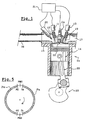
- FIG. 1 shows a cylinder 10 of a four-stroke internal combustion engine whose upper part forms a combustion chamber 12 delimited by a movable piston 14 and a cylinder head 15.
- a connecting rod 22 connects the piston 14 to a crankshaft 23.
- the cylinder 10 is supplied with an air / fuel mixture by an intake circuit 16 which opens into the combustion chamber 12 through an intake valve 18 whose displacements are controlled by a linear electromagnetic actuator 11 in order to seal or not the communication between the intake circuit 16 and the combustion chamber 12.
- An exhaust circuit 17 is provided for evacuation of the flue gases from the combustion chamber 12 through an exhaust valve 19 also controlled by an electromagnetic linear actuator 13.
- the control of the intake and exhaust valves 19 is provided by an electronic control unit 21 which controls the actuators 11, 13.
- the electronic unit 21 also controls the fuel injection, here indirectly, by means of an injector 20, as well as the ignition by means of a spark plug 24.
- the electronic control unit 21 notably comprises means for storing one or more engine operation maps.
- the electronic control unit 21 receives signals representative of operating parameters such as the engine speed, the atmospheric pressure, the pressure in each cylinder, the flow rate of the intake and / or exhaust gases, the instantaneous torque provided. etc.
- the four-stroke cycle of a combustion engine it is carried out in two rotations of the crankshaft 23 and in four races of the piston 14, the four stages of the cycle being the intake, the compression, the combustion and the exhaust.
- the rolls C1, C4 and cylinders C2, C3 are selected as primary cylinders so as to optimize the distribution over time of the electrical energy demands from cylinders C1, C2, C3, C4.
- crankshaft 23 the difference between two adjacent PM axes represents a half-turn of crankshaft 23.
- the horizontal axis referenced “Dem” represents the operation of the starter.
- Figure 2 a diagram which illustrates the operation of the method according to the invention.
- a prepositioning PS of the valves 18, 19 of the two primary cylinders C1, C4 is controlled simultaneously by placing the intake valves 18 in the closed position and the exhaust valves 19 in the open position to the maximum.
- This prepositioning PS - intake valve 18 closed and exhaust valve 19 open - is preferable to a prepositioning PS in which all the valves 18, 19 would be closed.
- a prepositioning PS is not chosen in which all the valves 18, 19 are open to the maximum, because this type of prepositioning PS communicates the intake circuit 16 with the exhaust circuit 17, which produces a phenomenon of "cross-flow", that is to say an invasion of the intake circuit 16 by the burnt gases, especially in case of hot start.
- the starter Dem is started, which is supplied with electric current by a battery of the motor, so as to cause the rotation of the crankshaft 23.
- This injection fuel INJ is therefore not synchronized with the angular position of the crankshaft 23.
- a prepositioning PS of the valves 18, 19 is controlled by placing the inlet valve 18 in the closed position and the valve of exhaust 19 in the open position to the maximum.
- prepositioning PS is commanded first on the cylinder C3, then on the cylinder C2.
- Knowing the angular position of the crankshaft 23 makes it possible to determine the high dead points PMH and low PMB of the stroke of the pistons 14 of each of the cylinders C1, C2, C3, C4, and thus to synchronize the opening and closing moments. valves 18, 19 depending on the intended cycle of operation.
- the angular position of the crankshaft 23 is determined by the angular reference mark RA at the instant of synchronization S.
- the detection of the angular reference mark RA here means that the piston 14 of the cylinder C1 is in its upward stroke, in the vicinity of its top dead center TDC.
- the displacement of the valves 18, 19 of the cylinders which have already been prepositioned PS here the primary cylinders C1, C4, is controlled so as to operate according to the conventional four-stroke mode of the engine.
- ignition ALL is triggered for the mixture, in accordance with the conventional mode of operation of a cylinder.
- the INJ injection of fuel into the cylinder C2 is controlled during the ADM admission phase of the cylinder C3 and an ADM admission phase is triggered in the vicinity of the top dead center PMH of the piston 14 of the cylinder C2. .
- the starting phase which has just been described with reference to FIG. 2, constitutes a favorable start-up case since the angular position of the crankshaft 23 has been determined from the first point PM of the cylinder C1 following the launching of the starter Dem.
- FIG. 3 shows an unfavorable start-up case in which the identification of the angular position takes place only after about one turn of crankshaft 23.
- FIG. 4 shows a mode of operation of the method when a low charge of the battery is detected at startup at time t0.
- the method according to the invention also comprises a particular mode of operation in case of hot start.
- the electronic unit 21 determines from sensors (not shown) whether one is in a hot start case.
- the operation is similar to that described above, with reference to FIG. 2, but after having controlled the prepositioning PS of the valves 18, 19 of the secondary cylinders C2, C3, and before controlling the operation of the secondary cylinders C2, C3 in the conventional mode, the secondary cylinders C2, C3 are operated in purge mode Mp in order to transfer to the exhaust circuit 17 at least a portion of the burnt gases that have filled the intake circuit 16 during engine shutdown.
- the principle of operation in the purge mode M p is to use the rotation "empty", therefore without fuel injection, of the crankshaft 23, by controlling the valves 18, 19 of the cylinder 10 adequately, to purge the circuit of admission 16 of the burnt gases that it contains, by evacuating them to the exhaust system 17.
- the purge mode Mp operates in a two-phase cycle which is illustrated in FIG.
- This two-phase cycle comprises an admission phase Pa of the flue gases during the downward stroke of the piston 14 from the top dead center TDC to the bottom dead center PMB.
- the admission phase Pa is limited by the opening of the intake valve 18 in the vicinity of the top dead center TDC and its closure in the vicinity of the bottom dead center PMB.
- the cylinder 10 thus fills with burnt gases that are initially contained in the intake circuit 16.
- the second phase is a flue gas evacuation phase that takes place during the upward stroke of the piston 14 from the bottom dead center PMB to the top dead center PMB.
- the exhaust phase Pe is bounded by the opening OE of the exhaust valve 19 in the vicinity of the bottom dead center PMB, after the closure FA of the intake valve 18, and the closure FE of the exhaust valve 19 in the vicinity of the top dead center TDC, before opening OA of the intake valve 18.
- the cylinder 10 thus flushes the burnt gases that it contains in the exhaust system 17.
- the succession of closures FA, FE and openings OA, OE valves 18, 19 is performed as quickly as possible given the technical possibilities of the valve control system 18, 19 and the system that provides them with energy, for example the battery.
- dead-center passages PMB, PMH are detected by known means, for example by means of graduated angular targets integral in rotation with the crankshaft 23.
- This type of operation notably makes it possible to reduce the energy consumption necessary for the opening and closing of the valves 18, 19.
- FIG. 6 shows an example of operation of the method according to the invention in the case of a hot start.
- the piston 14 of the cylinder C3 After its prepositioning PS, the piston 14 of the cylinder C3 is here in its downward stroke, therefore it starts its operation in purge mode Mp by a gas inlet phase Pa and then, during the upward stroke of its piston 14, it performs a gas evacuation phase Pe.
- the cylinder C3 In the vicinity of the top dead center TDC following the stroke of its piston 14, the cylinder C3 begins operation in the conventional four-stroke mode, in phase with the primary cylinders C1, C4.
- the operation in purge mode Mp of each secondary cylinder C2, C3 comprises a single admission phase Pa and a single evacuation phase Pe.
- the secondary cylinders C2, C3 to operate in purge mode Mp, if the prepositioning PS of the valves 18, 19 takes place after the synchronization S, then the prepositioning PS of the valves is controlled 18, 19 such that the cylinder C2, C3 is ready to operate in purge mode Mp from the dead point PM following the stroke of its piston 14.
- the fuel injection INJ is suspended in the cylinders C1, C2, C3, C4 having already had a fuel injecting phase INJ.
Landscapes
- Engineering & Computer Science (AREA)
- Mechanical Engineering (AREA)
- General Engineering & Computer Science (AREA)
- Chemical & Material Sciences (AREA)
- Combustion & Propulsion (AREA)
- Electrical Control Of Air Or Fuel Supplied To Internal-Combustion Engine (AREA)
- Output Control And Ontrol Of Special Type Engine (AREA)
- Combined Controls Of Internal Combustion Engines (AREA)
Claims (8)
- Verfahren zur Steuerung eines Verbrennungsmotors mit vier Takten zur Einspritzung im Hinblick auf ein Optimieren der Zeitdauer des Starts und im Hinblick auf ein Verteilen des Verbrauchs an elektrischer Energie während dem Start über die Zeit, bei welchem das Öffnen und das Schließen jedes Ventils (18, 19) durch ein lineares, elektromagnetisches Betätigungsglied (11, 13) gesteuert wird, das mit einer elektronischen Steuereinheit (21) verbunden ist,
dadurch gekennzeichnet, dass, wenn der Start des Motors nachgefragt wurde,• man für eine erste Gruppe von Zylindern oder primären Zylindern (C1, C4) nacheinander die nachfolgenden Operationen realisiert:- man vor dem Starten des Anlassers (Dem) eine Vorpositionierung (PS) der Ventile (18, 19) steuert, im Verlaufe derer man die Verstellung aller Ventile (18, 19) in eine geschlossene Stellung oder in eine maximal geöffnete Stellung steuert;- man nach dem Starten des Anlassers (Dem) die erste Einspritzung (INJ) von Kraftstoff in mindestens einen primären Zylinder (C1, C4) steuert, ohne die Feststellung der Winkelposition der Kurbelwelle (23) abzuwarten;- man, sobald man die Winkelposition der Kurbelwelle (23) festgestellt hat, die Zündung (ALL) und die Stellung der Ventile (18, 19) im Verhältnis zur Winkelposition der Kurbelwelle (23) synchronisiert im Hinblick auf ein Funktionieren gemäß dem herkömmlichen Zyklus mit vier Takten des Motors;• man für eine zweite Gruppe von Zylindern oder sekundären Zylindern (C2, C3) die nachfolgenden Operationen realisiert:- man nach dem Starten des Anlassers (Dem) für jeden sekundären Zylinder (C2, C3) nacheinender eine Vorpositionierung (PS) der Ventile (18, 19) steuert, in deren Verlauf man die Verstellung aller Ventile (18, 19) in eine geschlossene Stellung oder in eine maximal geöffnete Stellung steuert;- man für jeden sekundären Zylinder (C2, C3) seinen Betrieb gemäß dem herkömmlichen Zyklus steuert, wenn die Vorpositionierung (PS) der Ventile (18, 19) ausgeführt wird und wenn man die Winkelposition der Kurbelwelle (23) festgestellt hat. - Verfahren nach dem vorangegangenen Anspruch, dadurch gekennzeichnet, dass man gleichzeitig die erste Einspritzung (INJ) von Kraftstoff in alle primären Zylinder (C1, C4) steuert, ohne die Feststellung der Winkelposition der Kurbelwelle (23) abzuwarten.
- Verfahren nach irgendeinem der vorangegangenen Ansprüche, dadurch gekennzeichnet, dass man, wenn man die Vorpositionierung (PS) der Ventile (18, 19) der primären Zylinder (C1, C4) und sekundären Zylinder (C2, C3) steuert, entweder die Einlassventile (18) schließt und man die Auslassventile (19) maximal öffnet oder man die Einlassventile (18) maximal öffnet und man die Auslassventile (19) schließt.
- Verfahren nach dem vorangegangenen Anspruch, dadurch gekennzeichnet, dass man in der Phase des Warmstarts des Motors für mindestens einen sekundären Zylinder (C2, C3), nachdem man die Vorpositionierung (PS) seiner Ventile (18, 19) gesteuert hat und bevor man seinen Betrieb im herkömmlichen Modus steuert, seinen Betrieb in einem als Entleerung (Mp) bezeichneten Modus steuert, in welchem man nacheinander steuert:- in der Nähe des oberen Totpunkts (PMH) des Kolbens (14) das Schließen (FE) der Auslassventile (19) und das Öffnen (OA) von mindestens einem Einlassventil (18);- in der Nähe des unteren Totpunkts (PMB) des Kolbens (14) das Schließen (FA) der Einlassventile (18) und das Öffnen von mindestens einem Auslassventil (OE), derart, um mindestens einen Teil (16) der verbrannten Gase, welche die Einlassleitung (16) während dem Stopp des Motors gefüllt haben, in Richtung der Auslassleitung (17) umzufüllen.
- Verfahren nach dem vorangegangenen Anspruch, dadurch gekennzeichnet, dass man für die sekundären Zylinder (C2, C3), welche im Entleerungsmodus (Mp) betrieben werden, die Vorpositionierung (PS) der Ventile (18, 19) steuert, nachdem man die Winkelposition der Kurbelwelle (23) festgestellt hat und man die Ventile (18, 19) in Abhängigkeit von der Stellung des Kolbens (14) in dem Zylinder (C2, C3) derart positioniert, dass der Zylinder (C2, C3) bereit ist, im Entleerungsmodus (Mp) im nachfolgenden Totpunkt (PM) des Kolbens (14) betrieben zu werden.
- Verfahren nach irgendeinem der vorangegangenen Ansprüche, dadurch gekennzeichnet, dass man im Falle von aufeinanderfolgenden Fehlschlägen des Starts die Einspritzung (INJ) von Kraftstoff für die Zylinder (C1, C2, C3, C4) unterbricht, welche schon eine Einspritzungsphase (INJ) hatten.
- Verfahren nach irgendeinem der vorangegangenen Ansprüche, dadurch gekennzeichnet, dass, wenn man eine schwache Ladung der Batterie vor dem Start feststellt, man die Vorpositionierung (PS) der Ventile (18, 19) von jedem primären Zylinder (C1, C4) im Verhältnis zu den Vorpositionierungen (PS) der anderen primären Zylinder (C1, C4) in der Zeit verschiebt im Hinblick auf ein Glätten des elektrischen Stromverbrauchs über die Zeit, welcher für diese Vorpositionierungen (PS) notwendig ist.
- Verfahren nach irgendeinem der vorangegangenen Ansprüche, dadurch gekennzeichnet, dass man für jeden sekundären Zylinder (C2, C3) die erste Einspritzung (INJ) von Kraftstoff nach der Vorpositionierung (PS) von ihren Ventilen (18, 19) steuert, ohne abzuwarten, dass man in Phase mit dem herkömmlichen Zyklus ist.
Applications Claiming Priority (2)
| Application Number | Priority Date | Filing Date | Title |
|---|---|---|---|
| FR0015170 | 2000-11-24 | ||
| FR0015170A FR2817292B1 (fr) | 2000-11-24 | 2000-11-24 | Procede de commande d'un moteur a combustion en vue d'optimiser le demarrage |
Publications (2)
| Publication Number | Publication Date |
|---|---|
| EP1209341A1 EP1209341A1 (de) | 2002-05-29 |
| EP1209341B1 true EP1209341B1 (de) | 2006-01-11 |
Family
ID=8856826
Family Applications (1)
| Application Number | Title | Priority Date | Filing Date |
|---|---|---|---|
| EP01403004A Expired - Lifetime EP1209341B1 (de) | 2000-11-24 | 2001-11-23 | Verfahren zur Steuerung eines Verbrennungsmotors zur Optimierung des Starts |
Country Status (4)
| Country | Link |
|---|---|
| EP (1) | EP1209341B1 (de) |
| DE (1) | DE60116588T2 (de) |
| ES (1) | ES2251447T3 (de) |
| FR (1) | FR2817292B1 (de) |
Cited By (5)
| Publication number | Priority date | Publication date | Assignee | Title |
|---|---|---|---|---|
| US7532972B2 (en) | 2004-03-19 | 2009-05-12 | Ford Global Technologies, Llc | Method of torque control for an engine with valves that may be deactivated |
| US7549406B2 (en) | 2004-03-19 | 2009-06-23 | Ford Global Technologies, Llc | Engine shut-down for engine having adjustable valve timing |
| US7717071B2 (en) | 2004-03-19 | 2010-05-18 | Ford Global Technologies, Llc | Electromechanical valve timing during a start |
| US7743747B2 (en) | 2004-03-19 | 2010-06-29 | Ford Global Technologies, Llc | Electrically actuated valve deactivation in response to vehicle electrical system conditions |
| US8820049B2 (en) | 2004-03-19 | 2014-09-02 | Ford Global Technologies, Llc | Method to reduce engine emissions for an engine capable of multi-stroke operation and having a catalyst |
Families Citing this family (3)
| Publication number | Priority date | Publication date | Assignee | Title |
|---|---|---|---|---|
| US6997146B2 (en) * | 2002-05-22 | 2006-02-14 | Toyota Jidosha Kabushiki Kaisha | Start control method and apparatus for solenoid-operated valves of internal combustion engine |
| US7194993B2 (en) * | 2004-03-19 | 2007-03-27 | Ford Global Technologies, Llc | Starting an engine with valves that may be deactivated |
| FR2900447B1 (fr) * | 2006-04-26 | 2012-08-24 | Valeo Sys Controle Moteur Sas | Procede de demarrage d'un moteur thermique par allumage simultane dans deux cylindres |
Family Cites Families (5)
| Publication number | Priority date | Publication date | Assignee | Title |
|---|---|---|---|---|
| DE9420463U1 (de) | 1994-12-21 | 1996-04-25 | FEV Motorentechnik GmbH & Co. KG, 52078 Aachen | Elektromagnetisch betätigbare Stellvorrichtung |
| JPH11324744A (ja) * | 1998-05-19 | 1999-11-26 | Fuji Heavy Ind Ltd | 電磁駆動バルブの始動時制御装置 |
| US6092496A (en) * | 1998-09-04 | 2000-07-25 | Caterpillar Inc. | Cold starting method for diesel engine with variable valve timing |
| DE19851214C1 (de) * | 1998-11-06 | 1999-11-04 | Daimler Chrysler Ag | Verfahren zum Betrieb der Brennkraftmaschine eines Kraftfahrzeugs |
| JP2000257481A (ja) * | 1999-03-04 | 2000-09-19 | Honda Motor Co Ltd | 内燃機関の制御装置 |
-
2000
- 2000-11-24 FR FR0015170A patent/FR2817292B1/fr not_active Expired - Fee Related
-
2001
- 2001-11-23 ES ES01403004T patent/ES2251447T3/es not_active Expired - Lifetime
- 2001-11-23 EP EP01403004A patent/EP1209341B1/de not_active Expired - Lifetime
- 2001-11-23 DE DE60116588T patent/DE60116588T2/de not_active Expired - Lifetime
Cited By (5)
| Publication number | Priority date | Publication date | Assignee | Title |
|---|---|---|---|---|
| US7532972B2 (en) | 2004-03-19 | 2009-05-12 | Ford Global Technologies, Llc | Method of torque control for an engine with valves that may be deactivated |
| US7549406B2 (en) | 2004-03-19 | 2009-06-23 | Ford Global Technologies, Llc | Engine shut-down for engine having adjustable valve timing |
| US7717071B2 (en) | 2004-03-19 | 2010-05-18 | Ford Global Technologies, Llc | Electromechanical valve timing during a start |
| US7743747B2 (en) | 2004-03-19 | 2010-06-29 | Ford Global Technologies, Llc | Electrically actuated valve deactivation in response to vehicle electrical system conditions |
| US8820049B2 (en) | 2004-03-19 | 2014-09-02 | Ford Global Technologies, Llc | Method to reduce engine emissions for an engine capable of multi-stroke operation and having a catalyst |
Also Published As
| Publication number | Publication date |
|---|---|
| EP1209341A1 (de) | 2002-05-29 |
| DE60116588D1 (de) | 2006-04-06 |
| ES2251447T3 (es) | 2006-05-01 |
| FR2817292A1 (fr) | 2002-05-31 |
| DE60116588T2 (de) | 2006-08-10 |
| FR2817292B1 (fr) | 2003-01-24 |
Similar Documents
| Publication | Publication Date | Title |
|---|---|---|
| EP0156664B1 (de) | Verfahren zum Anlassen und zur Operation bei niedriger Last einer Dieselbrennkraftmaschine und Dieselbrennkraftmaschine versehen mit derartigem Verfahren | |
| EP1195505A1 (de) | Verfahren zur Steuerung der Selbstzündung in einem Viertaktmotor | |
| FR2822196A1 (fr) | Procede de demarrage sans demarreur d'un moteur a combustion interne a plusieurs cylindres | |
| FR2797304A1 (fr) | Procede de commande d'un moteur a combustion en vue de faciliter le demarrage du moteur apres un arret | |
| JP4823215B2 (ja) | 内燃機関の1グループのシリンダの動作の制御方法 | |
| EP1209341A1 (de) | Verfahren zur Steuerung eines Verbrennungsmotors zur Optimierung des Starts | |
| JP6791359B2 (ja) | エンジンの制御装置 | |
| FR2922162A1 (fr) | Systeme de motorisation hybride pneumatique-thermique de vehicule routier | |
| EP2077382B1 (de) | Verfahren für den Kaltstart eines Verbrennungsmotors, insbesondere eines selbstzündenden Verbrennungsmotors, und Motor, welcher dieses Verfahren verwendet | |
| EP1544434B1 (de) | Verfahren zur Steuerung einer abgasturbogeladenen Brennkraftmaschine | |
| FR2916799A1 (fr) | Procede et dispositif de commande de soupape avec plusieurs phases de levee, procede d'alimentation d'un moteur | |
| EP1069298B1 (de) | Verfahren zur Steuerung eines Verbrennungsmotors um das Versagen eines Ventiles zu kompensieren | |
| EP1138885B1 (de) | Verfahren zur Kontrolle einer Brennkraftmaschine zur Erleichterung des Startes | |
| EP1740808A2 (de) | Verfahren zur steuerung eines zylinderbetriebs für einen verbrennungsmotor | |
| EP1384862B1 (de) | Verfahren und Vorrichtung zur Regelung einer Brennkraftmaschine | |
| WO2006084660A1 (fr) | Procede pour controler le demarrage d’un moteur a combustion interne | |
| FR2795133A1 (fr) | Procede de commande d'un moteur a combustion en vue de l'obtention d'un effet de frein moteur | |
| EP1384863B1 (de) | Brennkraftmaschine mit einem Prozessor und elektromagnetischen Ventilaktuatoren | |
| WO2019073154A1 (fr) | Procédé et système de validation de la phase d'un moteur de véhicule | |
| EP1384861B1 (de) | Brennkraftmaschine mit Prozessor und Elektromechanische Antriebe zur Ventilsteuerung | |
| FR2652124A1 (fr) | Procede et appareil pour refouler a force de l'air dans un moteur a combustion interne apres la phase de combustion. | |
| EP2044312A2 (de) | Verfahren zur reduktion von hc-emissionen aus einem kältemotor mit externer kraftstoffeinspritzung und motor zur ausführung dieses verfahrens | |
| FR2979378A1 (fr) | Systeme d'alimentation en fluide et moteur a combustion interne comportant un tel systeme | |
| FR2904049A1 (fr) | Moteur thermique ayant deux conduits d'admission dont l'un est utilise pour balayer la chambre de combustion, module de gestion d'un tel moteur thermique et procede de gestion d'un moteur thermique | |
| FR2938880A1 (fr) | Moteur a recirculation de gaz d'echappement et vehicule comprenant le moteur |
Legal Events
| Date | Code | Title | Description |
|---|---|---|---|
| PUAI | Public reference made under article 153(3) epc to a published international application that has entered the european phase |
Free format text: ORIGINAL CODE: 0009012 |
|
| AK | Designated contracting states |
Kind code of ref document: A1 Designated state(s): AT BE CH CY DE DK ES FI FR GB GR IE IT LI LU MC NL PT SE TR |
|
| AX | Request for extension of the european patent |
Free format text: AL;LT;LV;MK;RO;SI |
|
| RAP1 | Party data changed (applicant data changed or rights of an application transferred) |
Owner name: RENAULT S.A.S. |
|
| AKX | Designation fees paid | ||
| 17P | Request for examination filed |
Effective date: 20021113 |
|
| RBV | Designated contracting states (corrected) |
Designated state(s): BE DE ES GB |
|
| REG | Reference to a national code |
Ref country code: DE Ref legal event code: 8566 |
|
| GRAP | Despatch of communication of intention to grant a patent |
Free format text: ORIGINAL CODE: EPIDOSNIGR1 |
|
| GRAS | Grant fee paid |
Free format text: ORIGINAL CODE: EPIDOSNIGR3 |
|
| GRAA | (expected) grant |
Free format text: ORIGINAL CODE: 0009210 |
|
| AK | Designated contracting states |
Kind code of ref document: B1 Designated state(s): BE DE ES GB |
|
| GBT | Gb: translation of ep patent filed (gb section 77(6)(a)/1977) |
Effective date: 20060222 |
|
| REF | Corresponds to: |
Ref document number: 60116588 Country of ref document: DE Date of ref document: 20060406 Kind code of ref document: P |
|
| REG | Reference to a national code |
Ref country code: ES Ref legal event code: FG2A Ref document number: 2251447 Country of ref document: ES Kind code of ref document: T3 |
|
| PLBE | No opposition filed within time limit |
Free format text: ORIGINAL CODE: 0009261 |
|
| STAA | Information on the status of an ep patent application or granted ep patent |
Free format text: STATUS: NO OPPOSITION FILED WITHIN TIME LIMIT |
|
| 26N | No opposition filed |
Effective date: 20061012 |
|
| PGFP | Annual fee paid to national office [announced via postgrant information from national office to epo] |
Ref country code: DE Payment date: 20141119 Year of fee payment: 14 Ref country code: ES Payment date: 20141126 Year of fee payment: 14 Ref country code: GB Payment date: 20141119 Year of fee payment: 14 |
|
| PGFP | Annual fee paid to national office [announced via postgrant information from national office to epo] |
Ref country code: BE Payment date: 20141118 Year of fee payment: 14 |
|
| REG | Reference to a national code |
Ref country code: DE Ref legal event code: R119 Ref document number: 60116588 Country of ref document: DE |
|
| GBPC | Gb: european patent ceased through non-payment of renewal fee |
Effective date: 20151123 |
|
| PG25 | Lapsed in a contracting state [announced via postgrant information from national office to epo] |
Ref country code: GB Free format text: LAPSE BECAUSE OF NON-PAYMENT OF DUE FEES Effective date: 20151123 Ref country code: DE Free format text: LAPSE BECAUSE OF NON-PAYMENT OF DUE FEES Effective date: 20160601 |
|
| PG25 | Lapsed in a contracting state [announced via postgrant information from national office to epo] |
Ref country code: ES Free format text: LAPSE BECAUSE OF NON-PAYMENT OF DUE FEES Effective date: 20151124 |
|
| PG25 | Lapsed in a contracting state [announced via postgrant information from national office to epo] |
Ref country code: BE Free format text: LAPSE BECAUSE OF NON-PAYMENT OF DUE FEES Effective date: 20151130 |
|
| REG | Reference to a national code |
Ref country code: ES Ref legal event code: FD2A Effective date: 20180710 |