EP1209351B1 - Brennstoffeinspritzventil mit piezoelektrischem Aktor - Google Patents
Brennstoffeinspritzventil mit piezoelektrischem Aktor Download PDFInfo
- Publication number
- EP1209351B1 EP1209351B1 EP01127223A EP01127223A EP1209351B1 EP 1209351 B1 EP1209351 B1 EP 1209351B1 EP 01127223 A EP01127223 A EP 01127223A EP 01127223 A EP01127223 A EP 01127223A EP 1209351 B1 EP1209351 B1 EP 1209351B1
- Authority
- EP
- European Patent Office
- Prior art keywords
- piston
- chamber
- module
- push
- assembled
- Prior art date
- Legal status (The legal status is an assumption and is not a legal conclusion. Google has not performed a legal analysis and makes no representation as to the accuracy of the status listed.)
- Expired - Lifetime
Links
- 239000000446 fuel Substances 0.000 title claims description 91
- 230000006835 compression Effects 0.000 claims description 13
- 238000007906 compression Methods 0.000 claims description 13
- 238000007789 sealing Methods 0.000 claims description 5
- 238000002485 combustion reaction Methods 0.000 claims description 4
- 239000011248 coating agent Substances 0.000 claims description 3
- 238000000576 coating method Methods 0.000 claims description 3
- 238000004891 communication Methods 0.000 claims description 2
- 239000000243 solution Substances 0.000 description 5
- 238000011084 recovery Methods 0.000 description 4
- 238000004519 manufacturing process Methods 0.000 description 3
- 230000004913 activation Effects 0.000 description 2
- 230000002706 hydrostatic effect Effects 0.000 description 2
- 230000036316 preload Effects 0.000 description 2
- 230000009471 action Effects 0.000 description 1
- 230000003321 amplification Effects 0.000 description 1
- 230000008901 benefit Effects 0.000 description 1
- 238000007599 discharging Methods 0.000 description 1
- 239000012530 fluid Substances 0.000 description 1
- 238000002347 injection Methods 0.000 description 1
- 239000007924 injection Substances 0.000 description 1
- 238000003199 nucleic acid amplification method Methods 0.000 description 1
- 230000009467 reduction Effects 0.000 description 1
Images


Classifications
-
- F—MECHANICAL ENGINEERING; LIGHTING; HEATING; WEAPONS; BLASTING
- F02—COMBUSTION ENGINES; HOT-GAS OR COMBUSTION-PRODUCT ENGINE PLANTS
- F02M—SUPPLYING COMBUSTION ENGINES IN GENERAL WITH COMBUSTIBLE MIXTURES OR CONSTITUENTS THEREOF
- F02M63/00—Other fuel-injection apparatus having pertinent characteristics not provided for in groups F02M39/00 - F02M57/00 or F02M67/00; Details, component parts, or accessories of fuel-injection apparatus, not provided for in, or of interest apart from, the apparatus of groups F02M39/00 - F02M61/00 or F02M67/00; Combination of fuel pump with other devices, e.g. lubricating oil pump
- F02M63/0012—Valves
- F02M63/0031—Valves characterized by the type of valves, e.g. special valve member details, valve seat details, valve housing details
- F02M63/0033—Lift valves, i.e. having a valve member that moves perpendicularly to the plane of the valve seat
- F02M63/0036—Lift valves, i.e. having a valve member that moves perpendicularly to the plane of the valve seat with spherical or partly spherical shaped valve member ends
-
- F—MECHANICAL ENGINEERING; LIGHTING; HEATING; WEAPONS; BLASTING
- F02—COMBUSTION ENGINES; HOT-GAS OR COMBUSTION-PRODUCT ENGINE PLANTS
- F02M—SUPPLYING COMBUSTION ENGINES IN GENERAL WITH COMBUSTIBLE MIXTURES OR CONSTITUENTS THEREOF
- F02M47/00—Fuel-injection apparatus operated cyclically with fuel-injection valves actuated by fluid pressure
- F02M47/02—Fuel-injection apparatus operated cyclically with fuel-injection valves actuated by fluid pressure of accumulator-injector type, i.e. having fuel pressure of accumulator tending to open, and fuel pressure in other chamber tending to close, injection valves and having means for periodically releasing that closing pressure
- F02M47/027—Electrically actuated valves draining the chamber to release the closing pressure
-
- F—MECHANICAL ENGINEERING; LIGHTING; HEATING; WEAPONS; BLASTING
- F02—COMBUSTION ENGINES; HOT-GAS OR COMBUSTION-PRODUCT ENGINE PLANTS
- F02M—SUPPLYING COMBUSTION ENGINES IN GENERAL WITH COMBUSTIBLE MIXTURES OR CONSTITUENTS THEREOF
- F02M61/00—Fuel-injectors not provided for in groups F02M39/00 - F02M57/00 or F02M67/00
- F02M61/16—Details not provided for in, or of interest apart from, the apparatus of groups F02M61/02 - F02M61/14
- F02M61/167—Means for compensating clearance or thermal expansion
-
- F—MECHANICAL ENGINEERING; LIGHTING; HEATING; WEAPONS; BLASTING
- F02—COMBUSTION ENGINES; HOT-GAS OR COMBUSTION-PRODUCT ENGINE PLANTS
- F02M—SUPPLYING COMBUSTION ENGINES IN GENERAL WITH COMBUSTIBLE MIXTURES OR CONSTITUENTS THEREOF
- F02M63/00—Other fuel-injection apparatus having pertinent characteristics not provided for in groups F02M39/00 - F02M57/00 or F02M67/00; Details, component parts, or accessories of fuel-injection apparatus, not provided for in, or of interest apart from, the apparatus of groups F02M39/00 - F02M61/00 or F02M67/00; Combination of fuel pump with other devices, e.g. lubricating oil pump
- F02M63/0012—Valves
- F02M63/0014—Valves characterised by the valve actuating means
- F02M63/0015—Valves characterised by the valve actuating means electrical, e.g. using solenoid
- F02M63/0026—Valves characterised by the valve actuating means electrical, e.g. using solenoid using piezoelectric or magnetostrictive actuators
Definitions
- the present invention relates to a fuel injector with a piezoelectric actuator.
- piezoelectric actuators can be used to obtain very fast injector opening and closing responses.
- the operating stroke of such a piezoelectric actuator is only about 1/1000 of the height of the piezo stack.
- a stroke amplification function has to be implemented in the injector.
- US patent 5,779,149 shows a fuel injector for an internal combustion engine using a hydraulic amplifier to increase the stroke of a piezoelectric actuator for opening a normally closed drain valve associated with a hydraulic control chamber.
- This stroke amplifier comprises a first piston and a second piston defining a hydraulic stroke amplifier chamber therebetween.
- a group of cup-shaped springs acts on the first piston to maintain a direct contact between the latter and the piezoelectric actuator.
- An actuation of the piezoelectric actuator causes a pressure rise in the fuel contained in the hydraulic stroke amplifier chamber.
- the fuel pressure in this chamber acts on the second piston, which has a smaller cross section than the first piston.
- the small piezoelectric actuator imposed to the first piston results in an amplified stroke of the second piston, which acts on the normally closed drain valve to open it.
- the pressure in the hydraulic stroke amplifier chamber drops.
- the force exerted by the second piston on the drain valve diminishes and the latter is closed by a closing spring.
- a refill valve is mounted in the injector body laterally of the hydraulic stroke amplifier to connect the hydraulic stroke amplifier chamber to a fuel recovery line. This refill valve enables to feed back fuel into the hydraulic chamber when the piezoelectric actuator is deactivated in order to compensate for fuel that has leaked out of the hydraulic stroke amplifier chamber during the compression stroke.
- a technical problem underlying the present invention is to provide a very simple solution for refilling a hydraulic stroke amplifier chamber of a piezoelectric fuel injector with fuel, wherein this solution should result in a compact fuel injector design and should not have negative consequences on the opening and closing responses of the fuel injector.
- This problem is solved by a fuel injector as claimed in claim 1.
- a fuel injector for an internal combustion engine in accordance with the present invention comprises a housing with an actuator chamber, a piezoelectric actuator arranged in the actuator chamber, an injector control valve and a hydraulic stroke amplifier module.
- the hydraulic stroke amplifier module is located axially in-between the injector control valve and the piezoelectric actuator. It comprises a first piston and a second piston defining a hydraulic stroke amplifier chamber therebetween. In this stroke amplifier chamber, the second piston has a smaller pressure effective cross-section than the first piston and is therefore capable of actuating the injector control valve with an amplified stroke.
- the fuel injector further includes a push-rod, a spring means associated with this push-rod and a fuel supply means for supplying fuel to the actuator chamber.
- the push-rod which has a first end and an opposite second end, is arranged in the actuator chamber axially between the first piston and the piezoelectric actuator.
- the first end of the push-rod is in contact with the piezoelectric actuator and the push-rod spring means is associated with the push-rod so as to press this first end of the push-rod against the piezoelectric actuator.
- the push-rod pre-loads the piezoelectric actuator and warrants that it operates always in a compressed mode.
- the second end of the push-rod is capable of entering into mechanical contact with the first piston for communicating to the latter a small compression stroke in the direction of the second piston when the piezoelectric actuator is activated.
- the first piston includes a through channel for hydraulically connecting the stroke amplifier chamber to the actuator chamber.
- this through channel is hydraulically closed off by the second end of the push-rod, which is in mechanical contact with the first piston to communicate the compression stroke to the latter.
- the push-rod spring causes the push-rod to move back very rapidly.
- the first piston follows the movement of the push-rod but at a lower speed. In other words, the slower first piston looses contact with the second end of the faster push-rod. The result is that the through channel in the first piston is no longer closed and can fulfil the function of a refill channel, allowing fuel contained in the actuator chamber to flow through the through channel of the first piston into the hydraulic stroke amplifier chamber to compensate for fuel leakage during the compression stroke.
- the fuel injector further comprises a hydraulic control chamber associated with the injector control valve, wherein the injector control valve establishes a hydraulic communication between the hydraulic control chamber and the actuator chamber when the piezoelectric actuator is activated.
- the injector control valve and its associated control chamber are used as fuel supply means for supplying fuel to the actuator chamber.
- the piezoelectric actuator is e.g. provided with a fuel-resistant coating and simply immersed an actuator chamber completely filled with fuel.
- the piezoelectric actuator may e.g. be separated from the push-rod by a fuel-resistant, easily deformable diaphragm. This diaphragm would divide the actuator chamber in a first section that contains the push-rod and is filled with fuel and a second section that contains the piezoelectric actuator and does not contain fuel.
- the stroke amplifier advantageously includes a spring for pushing its two pistons axially apart.
- This spring ensures direct mechanical contact between the first piston and the push-rod and the second piston and the control valve, before the piezoelectric actuator is activated.
- the aforementioned spring for pushing the two pistons apart is advantageously received in a spring chamber arranged in the second piston.
- this spring chamber has advantageously a central insert therein. A reduction of fuel volume in the hydraulic stroke amplifier chamber has indeed a positive influence on the opening and closing responses of the fuel injector.
- hydraulic stroke amplifier module of a fuel injector of the present invention can be easily conceived as a pre-assembled and pre-tested module, which is simply inserted in a bore of the injector housing.
- the present invention provides a fuel injector characterised by a general design concept that favours an easy an cost-effective manufacturing, assembly and testing.
- the control valve is part of a pre-assembled control valve module
- the hydraulic stroke amplifier module is a pre-assembled module
- the fuel injector further includes a pre-assembled needle valve module.
- the housing of this injector includes at least one tube, wherein the pre-assembled needle valve module, the pre-assembled control valve module, the pre-assembled hydraulic stroke amplifier module, the push-rod and the piezoelectric actuator are axially stacked within the at least one tube.
- the housing includes advantageously a first tube and a second tube, which are assembled by screwing an end of the second tube into an end of the first tube.
- the pre-assembled needle valve module and the pre-assembled control valve module are then stacked in the first tube and axially pressed together by the second tube, when the latter is screwed into the first tube.
- the pre-assembled needle valve module includes advantageously a module body having therein a first channel
- the pre-assembled control valve module includes a module body having therein a second channel
- the second tube has therein a third channel. This first, second and third channel co-operate to form a feeding line for pressurised fuel.
- the spring means which is associated with the push-rod, bears advantageously on the module body of the pre-assembled hydraulic stroke amplifier module in the second tube, to push this body axially against the body of the pre-assembled control valve module in the first tube.
- FIG. 1 shows a preferred embodiment of a fuel injector 10 for an internal combustion engine in accordance with the invention.
- This fuel injector 10 includes a tubular housing 12 consisting of a first tube 12a and a second tube 12b.
- Reference number 14 identifies a feeding line in the housing 12 connected to a so-called common rail (not shown) for feeding high pressure fuel to an injector needle valve, which is globally identified by reference number 15.
- This needle valve 15 comprises a closing needle 16 slidingly mounted in a needle valve body 17.
- the closing needle 16 is actuated by means of a control piston 18 defining a first pressure surface in a first control chamber 20 and a second pressure surface in a second control chamber 22.
- a closing spring 24 is associated with the control piston 18 in the second control chamber 22, so as to bias the closing needle 16 in the direction of arrow 26 in a closed position, in which the tip of the closing needle 16 closes outlet nozzles 27 in the tip of the needle valve body 17.
- the first control chamber 20 is filled with high pressure fuel through the feeding line 14. Small quantities of high pressure fuel may enter from the feeding line 14 through a flow restrictor channel 28 into the second control chamber 22. If the pressure in the second control chamber 22 equals the pressure in the first control chamber 20, then hydraulic forces acting on the closing needle 16 are substantially in equilibrium, and the closing spring 24 is therefore capable of maintaining the needle valve 15 closed. However, if the pressure in the second control chamber 22 falls below a certain value, a hydrostatic force acts on the closing needle in the opposite direction of arrow 26. The needle valve 15 opens as soon as this hydrostatic force exceeds the closing force of the closing spring 24.
- the fuel pressure inside the second control chamber 22 is controlled by means of a control valve 30. As long as the control valve 30 is closed, the pressure in the second control chamber 22 equals the pressure in the feed line 14. If the control valve 30 opens, pressurised fuel is drained through a drain channel 32 out of the second control chamber 22 and the pressure in the second control chamber 22 drops.
- the control valve 30 is actuated by a piezoelectric actuator 34 which is arranged in an actuator chamber 36 of the tubular housing 12.
- the piezoelectric actuator 34 has a convex spherical head 40 which engages a concave spherical or conical seat 41 formed in a first end of a push-rod 38 arranged in the lower part of the actuator chamber 36.
- a spring 42 bears indirectly on the housing 12 to press the push-rod 38 with its seat 41 against the head 40 of the piezoelectric actuator 34. It follows that the push-rod 38 pre-loads the piezoelectric actuator 34 with a compressive force.
- the actuator chamber 36 is entirely filled with fuel. Indeed, during the injection period, the control valve 30 is open, so that pressurised fuel contained in the second control chamber 22 discharges through the drain channel 32 into the lower part of the actuator chamber 36 around the push-rod 38 and the spring 42. This fuel can also flow along the push-rod 38 (see e.g. fuel passage 39) and fill the upper part of the actuator chamber 36, which contains the piezoelectric actuator 34 that is provided with a fuel resistant coating.
- Arrow 43 is a schematic representation of a fuel recovery line discharging the fuel from the actuator chamber 36 into low pressure fuel return circuit (not shown).
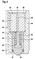
- Reference number 44 globally identifies a compact, pre-assembled hydraulic stroke amplifier module, which will be described in detail referring simultaneously to FIG. 1 & 4.
- This hydraulic stroke amplifier module 44 includes a cylindrical sleeve 46 which is closed at one end by a first piston 48 and at the other end by a second piston 50. Both pistons 48 and 50 are slideably guided within the sleeve 46 and define a small volume hydraulic stroke amplifier chamber 52 therebetween. It will be noted that the second piston 50 has in the hydraulic stroke amplifier chamber 52 an effective pressure surface smaller than that of the first piston 48.
- the first piston 48 has a flat front face 54 that is exposed at one end of the sleeve 46.
- the second piston 50 has a tip 56 that projects from the opposite end of the sleeve 46.
- a through-bore 58 extends axially through the first piston 48 into the hydraulic stroke amplifier chamber 52 and has an inlet 60 in the front face 54 of the first piston 48.
- a spacing spring 62 is mounted in a spring chamber 64 inside the second piston 50 so as to push both pistons axially apart.
- the volume of this spring chamber 64, and consequently of the hydraulic stroke amplifier chamber 52, is reduced by means of a central core 65, which is axially inserted in the spring chamber 64, so as to delimit therein an annular space for the spacing spring 62.
- Fuel is indeed compressible and the bigger the fuel volume between the two pistons is, the bigger will be the loss of output stroke of the stroke amplifier due to due to compression of the fuel.
- a first lock washer 66 forms an axial end-stop for the first piston 48 and a second lock washer 67 forms an axial end-stop for the second piston 50.
- the only function of these lock washers 66, 67 is to maintain the pistons 48, 50 within the sleeve 46 when the hydraulic stroke amplifier module 44 is pre-assembled outside the fuel injector 10.
- Reference number 68 in FIG. 4 identifies a groove in the sleeve 46, which forms part of the drain channel 32 in the assembled fuel injector 10.
- the operation of the hydraulic stroke amplifier 44 in the fuel injector 10 is as follows. Before the activation of the piezoelectric actuator 34, the hydraulic stroke amplifier module 44 must be in following operative state: (a) the hydraulic stroke amplifier chamber 52 is completely filled with fuel; (b) the second end of the push-rod 38 is in mechanical contact with the flat front face 54 of the first piston 48; and (c) the tip 56 of the second piston 50 is in mechanical contact with the closing element of the control valve 30.
- An activation of the piezoelectric actuator 34 causes a small stroke of the plunger 38 in the direction of arrow 26. The plunger 38 communicates this small stroke to the first piston 48; i.e. it pushes the first piston 48 in the direction of the second piston 50.
- This small stroke of the first piston 48 causes a rise of pressure in the hydraulic stroke amplifier chamber 52.
- the second piston 50 has in the hydraulic stroke amplifier chamber 52 an effective pressure surface smaller than that of the first piston 48, the second piston 50 will follow the first piston 48 with an amplified stroke.
- This amplified stroke allows to open the control valve 30, whereby the injector needle valve 15 opens as explained above.
- the plunger 38 bears with a flat end-face of its second end against the first front face 54 of the first piston 48, so that it hydraulically closes off the inlet 60 of the through-channel 58.
- first front face 54 of the first piston 48 and the end face of the second end of the plunger 38 form flat annular sealing surfaces around the inlet 60 that are co-operating to seal off the inlet of the through channel 58 during the compression stroke.
- sealing pressure i.e. the contact pressure between this sealing surfaces, increases proportionally with the pressure increase inside hydraulic stroke amplifier chamber 52 during the compression stroke of the first piston 48.
- the hydraulic stroke amplifier chamber 52 is automatically refilled with fuel from the actuator chamber 36 through the through channel 58, and when the piezoelectric actuator 34 is activated, the through channel 58 is hydraulically closed by the push-rod 38.
- the fuel injector shown in FIG. 1 has as a whole a design favouring an easy and cost-effective manufacturing, assembly and testing. This design will now be described in detail.
- the first tube 12a has an axial bore 74 in which a pre-assembled needle valve module 76 and a pre-assembled control valve module 78 are axially inserted one after the other.
- the pre-assembled needle valve module 76 includes the needle valve 15, i.e. the valve needle 16 and the needle valve body 17.
- the valve body 17 has a shoulder surface 80 that bears against a corresponding shoulder surface 82 of the first tube 12a. It forms at one end a tubular end portion 84 protruding out of the first tube 12a and at its axially opposite end a module interface surface 86 of the needle valve module 76.
- Reference number 88 identifies in the module interface surface 86 an inlet of a channel 14a.
- This channel 14a forms the feeding line 14 in the needle valve body 17 and discharges into the first control chamber 20, which is machined into the needle valve body 17 in axial alignment with a cylindrical bore 92 in which the control piston 18 is axially fitted.
- a projection 94 of the control piston 18 projects out of this cylindrical bore 92.
- the pre-assembled control valve module 78 includes a module body 96 with a first module interface surface 98 and a second module interface surface 100.
- the first module interface surface 98 abuts against the module interface surface 86 of the needle valve module 76.
- the second control chamber 22 is formed by a blind bore 102 extending from the first module interface surface 98 axially into the module body 96.
- the bottom surface 104 of this blind bore 102 forms a stop face co-operating with the projection 94 of the control piston 18 for defining an end-stop for the valve needle 16 in the opening direction, i.e. the opposite direction of the direction indicated by arrow 26.
- the closing spring 24 is mounted between the bottom surface 104 of the blind bore 102 and a shoulder surface 105 of the control piston 18.
- the control valve 30 is a spring closed check-valve that is mounted in a bore 106 extending between the bottom surface 104 of the blind bore 102 and the second module interface surface 100. It includes a closing ball 107, which is pushed by a spring 108 against a seat 109 to close off the bore 106 near the second module interface surface 100.
- Reference number 14b identifies a channel that extends through the module body 96 from first module interface surface 98 to the second module interface surface 100 to form the feeding line 14 therein. This channel 14b discharges through the inlet 88 in the needle valve module interface surface 86 into the channel 14a.
- the flow restrictor channel 28 is formed by a stepped, small diameter bore, which is obliquely drilled from the blind bore 102 into the channel 14b.
- the needle valve module 76 and the control valve module 78 are axially maintained in place by means of the second tube 12b.
- the latter is screwed with one end into the first tube 12a, so as to abut with an end face 111 (see FIG. 3) against the second module interface surface 100 (see FIG. 2) of the control valve module 78 and to be capable of firmly pressing the control valve module 78 against the needle valve module 76, which bears on the shoulder surface 82. It remains to be noted that both modules 76, 78 are blocked against rotation in the axial bore 74 of the tube 12a.
- the second tube 12b has an eccentric bore 112 in which the piezoelectric actuator 34, the pushing rod 38 with its spring 42 and the pre-assembled hydraulic stroke amplifier module 44 are axially inserted one after the other.
- the piezoelectric actuator 34 axially abuts against an axial stop face of the second tube 12b (schematically indicated by reference number 114).
- the spring 42 bears via the push-rod 38 on the piezoelectric actuator 34 and via a washer 116 on the sleeve 46 of the pre-assembled hydraulic stroke amplifier module 44, to push this sleeve 46 against the second module interface surface 100 (see FIG. 1 & 2).
- Reference number 14c identifies a channel that extends through the second tube 12b to form the feeding line 14 therein. This channel 14c discharges into the channel 14b in the module body 96 of the control valve module 78.
- the functional modules 76, 78 and 44 can be manufactured, assembled and tested separately and then easily assembled with the injector housing 12a, 12b, the piezoelectric actuator, the push-rod 38 and its spring 42 to form the finished fuel injector 10 shown in FIG. 1. This means lower production costs and better quality.
Landscapes
- Engineering & Computer Science (AREA)
- Chemical & Material Sciences (AREA)
- Combustion & Propulsion (AREA)
- Mechanical Engineering (AREA)
- General Engineering & Computer Science (AREA)
- Physics & Mathematics (AREA)
- Fluid Mechanics (AREA)
- Fuel-Injection Apparatus (AREA)
Claims (12)
- Brennstoffeinspritzventil (10) für eine Brennkraftmaschine, umfassend:dadurch gekennzeichnet, dassein Gehäuse (12) mit einer Aktorkammer (36) darin;einen piezoelektrischen Aktor (34), der in der Aktorkammer (36) angeordnet ist;ein Einspritzsteuerventil (30), das im Gehäuse (12) angeordnet ist; undein hydraulisches Hubverstärkermodul (44), das axial zwischen dem Einspritzsteuerventil (30) und dem piezoelektrischen Aktor (34) angeordnet ist, wobei das hydraulische Hubverstärkermodul einen ersten Kolben (48) und einen zweiten Kolben (50) umfasst, die dazwischen eine hydraulische Hubverstärkerkammer (52) definieren, wobei der zweite Kolben (50) einen kleineren druckwirksamen Querschnitt als der erste Kolben (48) aufweist und mit dem Einspritzsteuerventil (30) zusammenwirkt, um Letzteres zu betätigen;
das Brennstoffeinspritzventil (10) ferner umfasst:der erste Kolben (48) einen Durchlasskanal (58) umfasst, um die hydraulische Hubverstärkerkammer (52) und die Aktorkammer (36) hydraulisch zu verbinden; undeine Schubstange (38), die in der Aktorkammer (36) axial zwischen dem ersten Kolben (48) und dem piezoelektrischen Aktor (34) angeordnet ist, wobei die Schubstange (38) ein erstes und ein zweites Ende aufweist, wobei das erste Ende in Kontakt mit dem piezoelektrischen Aktor (34) steht und das zweite Ende in Kontakt mit dem ersten Kolben (48) treten kann, um Letzterem einen Verdichtungshub in Richtung des zweiten Kolbens (50) zu übertragen;ein Federmittel (42), das der Schubstange (38) zugeordnet ist, um so das erste Ende der Schubstange (38) gegen den piezoelektrischen Aktor (34) zu drücken; undein Brennstoffzuführmittel (32, 39), um der Aktorkammer (36) Brennstoff zuzuführen;
die Schubstange (38) den Durchlasskanal (58) hydraulisch verschließt, wenn sie in Kontakt mit dem ersten Kolben (48) steht, um Letzterem den Verdichtungshub zu übertragen. - Brennstoffeinspritzventil nach Anspruch 1, ferner umfassend eine hydraulische Steuerkammer (20), die dem Einspritzsteuerventil (30) zugeordnet ist; wobei das Einspritzsteuerventil (30) eine hydraulische Verbindung zwischen der hydraulischen Steuerkammer (20) und der Aktorkammer (36) herstellt, wenn der piezoelektrische Aktor (34) betätigt wird.
- Brennstoffeinspritzventil nach Anspruch 1 oder 2, dadurch gekennzeichnet, dass das zweite Ende der Schubstange (38) und der erste Kolben (48) ebene Dichtflächen aufweisen, die zusammenwirken, um den Durchlasskanal (58) zu verschließen, wenn das zweite Ende der Schubstange (38) in Kontakt mit dem ersten Kolben (48) steht, um Letzterem den Verdichtungshub zu übertragen.
- Brennstoffeinspritzventil nach irgendeinem der Ansprüche 1 bis 3, dadurch gekennzeichnet, dass der piezoelektrische Aktor (34) in den Brennstoff in der Aktorkammer (36) eingetaucht ist und mit einer brennstoffbeständigen Beschichtung versehen ist.
- Brennstoffeinspritzventil nach irgendeinem der Ansprüche 1 bis 4, dadurch gekennzeichnet, dass das hydraulische Hubverstärkermodul (44) ferner eine Feder (62) zum Auseinanderdrücken der zwei Kolben (48, 50) umfasst.
- Brennstoffeinspritzventil nach Anspruch 5, dadurch gekennzeichnet, dass:der zweite Kolben einen Federraum (64) aufweist, in dem die Feder (62) zum Auseinanderdrücken der zwei Kolben (48, 50) untergebracht ist; undder Federraum (64) darin einen mittigen Einsatz aufweist, um das Brennstoffvolumen in der hydraulischen Hubverstärkerkammer (52) zu minimieren.
- Brennstoffeinspritzventil nach irgendeinem der Ansprüche 1 bis 6, dadurch gekennzeichnet, dass der erste Kolben (48) und der zweite Kolben (50) in einer Buchse (46) eingebaut sind, um so ein vorgefertigtes hydraulisches Hubverstärkermodul (44) auszubilden, das in eine Bohrung (112) des Gehäuses (12b) einzuführen ist.
- Brennstoffeinspritzventil nach irgendeinem der Ansprüche 1 bis 7, dadurch gekennzeichnet, dass:das Steuerventil (30) Teil eines vorgefertigten Steuerventilmoduls (78) ist, das einen Modulkörper (96) umfasst;das hydraulische Hubverstärkermodul (44) ein vorgefertigtes Modul ist, das einen Modulkörper (46) umfasst;das Brennstoffeinspritzventil ferner ein vorgefertigtes Nadelventilmodul (76) umfasst, das einen Modulkörper (17) umfasst;das Gehäuse (12) mindestens ein Rohr (12a, 12b) umfasst; unddas vorgefertigte Nadelventilmodul (76), das vorgefertigte Steuerventilmodul (78), das vorgefertigte hydraulische Hubverstärkermodul (44), die Schubstange (38) und der piezoelektrische Aktor (34) axial in dem mindestens einen Rohr (12a, 12b) gestapelt sind.
- Brennstoffeinspritzventil nach Anspruch 8, dadurch gekennzeichnet, dass:das Gehäuse (12) ein erstes Rohr (12a) und ein zweites Rohr (12b) umfasst, die zusammengebaut werden, indem ein Ende des zweiten Rohrs (12b) in ein Ende des ersten Rohrs (12a) eingeschraubt wird;das vorgefertigte Nadelventilmodul (76) und das vorgefertigte Steuerventilmodul (78) im ersten Rohr (12a) gestapelt sind und axial durch das zweite Rohr (12b) zusammengedrückt werden; unddas vorgefertigte hydraulische Hubverstärkermodul (44), die Schubstange (38) und der piezoelektrische Aktor (34) axial im zweiten Rohr (12b) gestapelt sind.
- Brennstoffeinspritzventil nach Anspruch 9, dadurch gekennzeichnet, dass:wobei der erste (14a), zweite (14b) und dritte Kanal (14c) zusammenwirken, um eine Zulaufleitung (14) für unter Druck stehenden Brennstoff auszubilden.das vorgefertigte Nadelventilmodul (76) einen ersten Kanal (14a) in seinem Modulkörper (17) umfasst;das vorgefertigte Steuerventilmodul (78) einen zweiten Kanal (14b) in seinem Modulkörper (96) umfasst; unddas zweite Rohr (12b) darin einen dritten Kanal (14c) aufweist;
- Brennstoffeinspritzventil nach Anspruch 9 oder 10, dadurch gekennzeichnet, dass das der Schubstange (38) zugeordnete Federmittel (42) auf dem Modulkörper (46) des vorgefertigten hydraulischen Hubverstärkermoduls (44) im zweiten Rohr (12b) lagert, um diesen Körper (46) axial gegen den Körper (96) des vorgefertigten Steuerventilmoduls (78) im ersten Rohr (12a) zu drücken.
- Kompaktes hydraulisches Hubverstärkermodul, umfassend:dadurch gekennzeichnet, dasseine Buchse;einen ersten Kolben (48) und einen zweiten Kolben (50), die so in der Buchse eingebaut sind, dass sie eine hydraulische Hubverstärkerkammer (52) dazwischen definieren, wobei der erste und der zweite Kolben (48, 50) unterschiedliche druckwirksame Querschnitte in der hydraulischen Hubverstärkerkammer (52) aufweisen, wobei der erste Kolben (48) eine freie Endfläche (54) aufweist, an der eine Schubstange (38) anliegen kann, um den ersten Kolben (48) zum zweiten Kolben (50) zu drücken; undein Federmittel, das dem ersten Kolben (48) und dem zweiten Kolben (50) zugeordnet ist, um die zwei Kolben (48, 50) axial auseinander vorzuspannen;
der erste Kolben (48) einen Durchlasskanal (58) umfasst, um die hydraulische Hubverstärkerkammer (52) hydraulisch mit einem Einlass (60) zu verbinden, der so in der freien Endfläche (54) des ersten Kolbens (48) angeordnet ist, dass der Einlass (60) durch die Schubstange (38) verschlossen werden kann, wenn Letztere an der freien Endfläche (54) anliegt.
Applications Claiming Priority (2)
| Application Number | Priority Date | Filing Date | Title |
|---|---|---|---|
| LU90684 | 2000-11-28 | ||
| LU90684A LU90684B1 (en) | 2000-11-28 | 2000-11-28 | Fuel injector with piezoelectric actuator |
Publications (2)
| Publication Number | Publication Date |
|---|---|
| EP1209351A1 EP1209351A1 (de) | 2002-05-29 |
| EP1209351B1 true EP1209351B1 (de) | 2005-06-01 |
Family
ID=19731952
Family Applications (1)
| Application Number | Title | Priority Date | Filing Date |
|---|---|---|---|
| EP01127223A Expired - Lifetime EP1209351B1 (de) | 2000-11-28 | 2001-11-16 | Brennstoffeinspritzventil mit piezoelektrischem Aktor |
Country Status (3)
| Country | Link |
|---|---|
| EP (1) | EP1209351B1 (de) |
| DE (1) | DE60111164T2 (de) |
| LU (1) | LU90684B1 (de) |
Cited By (2)
| Publication number | Priority date | Publication date | Assignee | Title |
|---|---|---|---|---|
| US8997718B2 (en) | 2008-01-07 | 2015-04-07 | Mcalister Technologies, Llc | Fuel injector actuator assemblies and associated methods of use and manufacture |
| US9091238B2 (en) | 2012-11-12 | 2015-07-28 | Advanced Green Technologies, Llc | Systems and methods for providing motion amplification and compensation by fluid displacement |
Families Citing this family (5)
| Publication number | Priority date | Publication date | Assignee | Title |
|---|---|---|---|---|
| DE10133265A1 (de) * | 2001-07-09 | 2003-01-23 | Bosch Gmbh Robert | Brennstoffeinspritzventil |
| DE102005024871A1 (de) * | 2005-05-31 | 2006-12-07 | Siemens Ag | Injektor, insbesondere Kraftstoffinjektor |
| DE102005028135A1 (de) * | 2005-06-17 | 2006-12-28 | Robert Bosch Gmbh | Brennstoffeinspritzventil |
| US20140130773A1 (en) * | 2012-11-12 | 2014-05-15 | Mcalister Technologies, Llc | Mechanical motion amplification for new thermodynamic cycles |
| US9309846B2 (en) | 2012-11-12 | 2016-04-12 | Mcalister Technologies, Llc | Motion modifiers for fuel injection systems |
Family Cites Families (4)
| Publication number | Priority date | Publication date | Assignee | Title |
|---|---|---|---|---|
| EP0529630B1 (de) * | 1991-08-30 | 1996-03-27 | Nippondenso Co., Ltd. | Brennstoffeinspritzvorrichtung für Brennkraftmaschine |
| DE19500706C2 (de) * | 1995-01-12 | 2003-09-25 | Bosch Gmbh Robert | Zumeßventil zur Dosierung von Flüssigkeiten oder Gasen |
| US5779149A (en) | 1996-07-02 | 1998-07-14 | Siemens Automotive Corporation | Piezoelectric controlled common rail injector with hydraulic amplification of piezoelectric stroke |
| DE19701288C2 (de) * | 1997-01-16 | 1999-10-14 | Daimler Benz Ag | Ventil zur dosierten Abgabe von Fluiden |
-
2000
- 2000-11-28 LU LU90684A patent/LU90684B1/en active
-
2001
- 2001-11-16 EP EP01127223A patent/EP1209351B1/de not_active Expired - Lifetime
- 2001-11-16 DE DE60111164T patent/DE60111164T2/de not_active Expired - Lifetime
Cited By (2)
| Publication number | Priority date | Publication date | Assignee | Title |
|---|---|---|---|---|
| US8997718B2 (en) | 2008-01-07 | 2015-04-07 | Mcalister Technologies, Llc | Fuel injector actuator assemblies and associated methods of use and manufacture |
| US9091238B2 (en) | 2012-11-12 | 2015-07-28 | Advanced Green Technologies, Llc | Systems and methods for providing motion amplification and compensation by fluid displacement |
Also Published As
| Publication number | Publication date |
|---|---|
| DE60111164D1 (de) | 2005-07-07 |
| EP1209351A1 (de) | 2002-05-29 |
| DE60111164T2 (de) | 2006-03-16 |
| LU90684B1 (en) | 2002-05-29 |
Similar Documents
| Publication | Publication Date | Title |
|---|---|---|
| US5505384A (en) | Rate shaping control valve for fuel injection nozzle | |
| US5779149A (en) | Piezoelectric controlled common rail injector with hydraulic amplification of piezoelectric stroke | |
| RU2193683C2 (ru) | Гидрораспределительный клапан | |
| CZ291253B6 (cs) | Vstřikovací ventil paliva | |
| JPS63201362A (ja) | 内燃機関の噴射弁を介する燃料噴射を制御する圧電制御弁 | |
| US5852997A (en) | Common rail injector | |
| PL201040B1 (pl) | Paliwowy zawór wtryskowy do silników spalinowych | |
| JP2007510849A (ja) | 内燃機関の燃焼室内に燃料を噴射するインジェクタ、特にピエゾアクチュエータによって制御されるコモンレール・インジェクタ | |
| CN102812232B (zh) | 用于内燃机的高压燃料喷射阀 | |
| JP2010507746A (ja) | 軸方向で圧力補償された制御弁を備えたインジェクタ | |
| US4317541A (en) | Fuel injector-pump unit with hydraulic needle fuel injector | |
| EP1209351A1 (de) | Brennstoffeinspritzventil mit piezoelektrischem Aktor | |
| US6260541B1 (en) | Hydraulic lash adjuster | |
| KR20020061614A (ko) | 유체 제어용 밸브 | |
| US6732949B1 (en) | Fuel injection valve for internal combustion engines | |
| US6581850B1 (en) | Fuel injection valve for internal combustion engines | |
| US6626372B2 (en) | Injector with control part guidance | |
| US6129072A (en) | Hydraulically actuated device having a ball valve member | |
| US6840458B2 (en) | Fuel injector | |
| US4065058A (en) | Fuel injection nozzle with compressible valve | |
| JP2004537001A (ja) | 液体制御弁 | |
| US6530556B1 (en) | Control unit for controlling a pressure build-up in a pump unit | |
| JPH0286956A (ja) | ユニットインジェクタ | |
| JPH0444843Y2 (de) | ||
| US6923382B2 (en) | Hydraulically actuated injector with delay piston and method of using the same |
Legal Events
| Date | Code | Title | Description |
|---|---|---|---|
| PUAI | Public reference made under article 153(3) epc to a published international application that has entered the european phase |
Free format text: ORIGINAL CODE: 0009012 |
|
| AK | Designated contracting states |
Kind code of ref document: A1 Designated state(s): AT BE CH CY DE DK ES FI FR GB GR IE IT LI LU MC NL PT SE TR |
|
| AX | Request for extension of the european patent |
Free format text: AL;LT;LV;MK;RO;SI |
|
| 17P | Request for examination filed |
Effective date: 20020708 |
|
| AKX | Designation fees paid |
Designated state(s): DE FR GB |
|
| GRAP | Despatch of communication of intention to grant a patent |
Free format text: ORIGINAL CODE: EPIDOSNIGR1 |
|
| GRAS | Grant fee paid |
Free format text: ORIGINAL CODE: EPIDOSNIGR3 |
|
| GRAA | (expected) grant |
Free format text: ORIGINAL CODE: 0009210 |
|
| AK | Designated contracting states |
Kind code of ref document: B1 Designated state(s): DE FR GB |
|
| REG | Reference to a national code |
Ref country code: GB Ref legal event code: FG4D |
|
| REF | Corresponds to: |
Ref document number: 60111164 Country of ref document: DE Date of ref document: 20050707 Kind code of ref document: P |
|
| ET | Fr: translation filed | ||
| PLBE | No opposition filed within time limit |
Free format text: ORIGINAL CODE: 0009261 |
|
| STAA | Information on the status of an ep patent application or granted ep patent |
Free format text: STATUS: NO OPPOSITION FILED WITHIN TIME LIMIT |
|
| 26N | No opposition filed |
Effective date: 20060302 |
|
| PGFP | Annual fee paid to national office [announced via postgrant information from national office to epo] |
Ref country code: GB Payment date: 20091111 Year of fee payment: 9 |
|
| REG | Reference to a national code |
Ref country code: FR Ref legal event code: TP |
|
| GBPC | Gb: european patent ceased through non-payment of renewal fee |
Effective date: 20101116 |
|
| PG25 | Lapsed in a contracting state [announced via postgrant information from national office to epo] |
Ref country code: GB Free format text: LAPSE BECAUSE OF NON-PAYMENT OF DUE FEES Effective date: 20101116 |
|
| REG | Reference to a national code |
Ref country code: FR Ref legal event code: TP Owner name: DELPHI INTERNATIONAL OPERATIONS LUXEMBOURG S.A, LU Effective date: 20140516 |
|
| REG | Reference to a national code |
Ref country code: DE Ref legal event code: R082 Ref document number: 60111164 Country of ref document: DE Representative=s name: MANITZ, FINSTERWALD & PARTNER GBR, DE |
|
| REG | Reference to a national code |
Ref country code: DE Ref legal event code: R082 Ref document number: 60111164 Country of ref document: DE Representative=s name: MANITZ, FINSTERWALD & PARTNER GBR, DE Effective date: 20140702 Ref country code: DE Ref legal event code: R081 Ref document number: 60111164 Country of ref document: DE Owner name: DELPHI INTERNATIONAL OPERATIONS LUXEMBOURG S.A, LU Free format text: FORMER OWNER: DELPHI TECHNOLOGIES HOLDING S.A.R.L., BASCHARAGE, LU Effective date: 20140702 Ref country code: DE Ref legal event code: R082 Ref document number: 60111164 Country of ref document: DE Representative=s name: MANITZ FINSTERWALD PATENTANWAELTE PARTMBB, DE Effective date: 20140702 |
|
| REG | Reference to a national code |
Ref country code: FR Ref legal event code: PLFP Year of fee payment: 15 |
|
| REG | Reference to a national code |
Ref country code: FR Ref legal event code: PLFP Year of fee payment: 16 |
|
| REG | Reference to a national code |
Ref country code: FR Ref legal event code: PLFP Year of fee payment: 17 |
|
| PGFP | Annual fee paid to national office [announced via postgrant information from national office to epo] |
Ref country code: DE Payment date: 20171129 Year of fee payment: 17 Ref country code: FR Payment date: 20171127 Year of fee payment: 17 |
|
| REG | Reference to a national code |
Ref country code: DE Ref legal event code: R119 Ref document number: 60111164 Country of ref document: DE |
|
| PG25 | Lapsed in a contracting state [announced via postgrant information from national office to epo] |
Ref country code: DE Free format text: LAPSE BECAUSE OF NON-PAYMENT OF DUE FEES Effective date: 20190601 Ref country code: FR Free format text: LAPSE BECAUSE OF NON-PAYMENT OF DUE FEES Effective date: 20181130 |