EP1209354A1 - Dispositif de demarrage/arret d'un moteur de vehicule - Google Patents
Dispositif de demarrage/arret d'un moteur de vehicule Download PDFInfo
- Publication number
- EP1209354A1 EP1209354A1 EP00940795A EP00940795A EP1209354A1 EP 1209354 A1 EP1209354 A1 EP 1209354A1 EP 00940795 A EP00940795 A EP 00940795A EP 00940795 A EP00940795 A EP 00940795A EP 1209354 A1 EP1209354 A1 EP 1209354A1
- Authority
- EP
- European Patent Office
- Prior art keywords
- engine
- stopping
- vehicle
- starter motor
- starting
- Prior art date
- Legal status (The legal status is an assumption and is not a legal conclusion. Google has not performed a legal analysis and makes no representation as to the accuracy of the status listed.)
- Granted
Links
Images




Classifications
-
- F—MECHANICAL ENGINEERING; LIGHTING; HEATING; WEAPONS; BLASTING
- F02—COMBUSTION ENGINES; HOT-GAS OR COMBUSTION-PRODUCT ENGINE PLANTS
- F02N—STARTING OF COMBUSTION ENGINES; STARTING AIDS FOR SUCH ENGINES, NOT OTHERWISE PROVIDED FOR
- F02N11/00—Starting of engines by means of electric motors
- F02N11/04—Starting of engines by means of electric motors the motors being associated with current generators
-
- F—MECHANICAL ENGINEERING; LIGHTING; HEATING; WEAPONS; BLASTING
- F02—COMBUSTION ENGINES; HOT-GAS OR COMBUSTION-PRODUCT ENGINE PLANTS
- F02N—STARTING OF COMBUSTION ENGINES; STARTING AIDS FOR SUCH ENGINES, NOT OTHERWISE PROVIDED FOR
- F02N11/00—Starting of engines by means of electric motors
- F02N11/08—Circuits specially adapted for starting of engines
- F02N11/0814—Circuits specially adapted for starting of engines comprising means for controlling automatic idle-start-stop
-
- H—ELECTRICITY
- H02—GENERATION; CONVERSION OR DISTRIBUTION OF ELECTRIC POWER
- H02K—DYNAMO-ELECTRIC MACHINES
- H02K7/00—Arrangements for handling mechanical energy structurally associated with dynamo-electric machines, e.g. structural association with mechanical driving motors or auxiliary dynamo-electric machines
- H02K7/006—Structural association of a motor or generator with the drive train of a motor vehicle
-
- H—ELECTRICITY
- H02—GENERATION; CONVERSION OR DISTRIBUTION OF ELECTRIC POWER
- H02K—DYNAMO-ELECTRIC MACHINES
- H02K7/00—Arrangements for handling mechanical energy structurally associated with dynamo-electric machines, e.g. structural association with mechanical driving motors or auxiliary dynamo-electric machines
- H02K7/10—Structural association with clutches, brakes, gears, pulleys or mechanical starters
- H02K7/1004—Structural association with clutches, brakes, gears, pulleys or mechanical starters with pulleys
- H02K7/1012—Machine arranged inside the pulley
- H02K7/1016—Machine of the outer rotor type
-
- H—ELECTRICITY
- H02—GENERATION; CONVERSION OR DISTRIBUTION OF ELECTRIC POWER
- H02K—DYNAMO-ELECTRIC MACHINES
- H02K7/00—Arrangements for handling mechanical energy structurally associated with dynamo-electric machines, e.g. structural association with mechanical driving motors or auxiliary dynamo-electric machines
- H02K7/18—Structural association of electric generators with mechanical driving motors, e.g. with turbines
- H02K7/1807—Rotary generators
- H02K7/1815—Rotary generators structurally associated with reciprocating piston engines
-
- F—MECHANICAL ENGINEERING; LIGHTING; HEATING; WEAPONS; BLASTING
- F02—COMBUSTION ENGINES; HOT-GAS OR COMBUSTION-PRODUCT ENGINE PLANTS
- F02N—STARTING OF COMBUSTION ENGINES; STARTING AIDS FOR SUCH ENGINES, NOT OTHERWISE PROVIDED FOR
- F02N2200/00—Parameters used for control of starting apparatus
- F02N2200/02—Parameters used for control of starting apparatus said parameters being related to the engine
- F02N2200/023—Engine temperature
-
- F—MECHANICAL ENGINEERING; LIGHTING; HEATING; WEAPONS; BLASTING
- F02—COMBUSTION ENGINES; HOT-GAS OR COMBUSTION-PRODUCT ENGINE PLANTS
- F02N—STARTING OF COMBUSTION ENGINES; STARTING AIDS FOR SUCH ENGINES, NOT OTHERWISE PROVIDED FOR
- F02N2200/00—Parameters used for control of starting apparatus
- F02N2200/06—Parameters used for control of starting apparatus said parameters being related to the power supply or driving circuits for the starter
- F02N2200/061—Battery state of charge [SOC]
-
- F—MECHANICAL ENGINEERING; LIGHTING; HEATING; WEAPONS; BLASTING
- F02—COMBUSTION ENGINES; HOT-GAS OR COMBUSTION-PRODUCT ENGINE PLANTS
- F02N—STARTING OF COMBUSTION ENGINES; STARTING AIDS FOR SUCH ENGINES, NOT OTHERWISE PROVIDED FOR
- F02N2200/00—Parameters used for control of starting apparatus
- F02N2200/08—Parameters used for control of starting apparatus said parameters being related to the vehicle or its components
- F02N2200/0801—Vehicle speed
-
- F—MECHANICAL ENGINEERING; LIGHTING; HEATING; WEAPONS; BLASTING
- F02—COMBUSTION ENGINES; HOT-GAS OR COMBUSTION-PRODUCT ENGINE PLANTS
- F02N—STARTING OF COMBUSTION ENGINES; STARTING AIDS FOR SUCH ENGINES, NOT OTHERWISE PROVIDED FOR
- F02N2200/00—Parameters used for control of starting apparatus
- F02N2200/08—Parameters used for control of starting apparatus said parameters being related to the vehicle or its components
- F02N2200/0802—Transmission state, e.g. gear ratio or neutral state
-
- F—MECHANICAL ENGINEERING; LIGHTING; HEATING; WEAPONS; BLASTING
- F02—COMBUSTION ENGINES; HOT-GAS OR COMBUSTION-PRODUCT ENGINE PLANTS
- F02N—STARTING OF COMBUSTION ENGINES; STARTING AIDS FOR SUCH ENGINES, NOT OTHERWISE PROVIDED FOR
- F02N2200/00—Parameters used for control of starting apparatus
- F02N2200/08—Parameters used for control of starting apparatus said parameters being related to the vehicle or its components
- F02N2200/0806—Air condition state
-
- F—MECHANICAL ENGINEERING; LIGHTING; HEATING; WEAPONS; BLASTING
- F02—COMBUSTION ENGINES; HOT-GAS OR COMBUSTION-PRODUCT ENGINE PLANTS
- F02N—STARTING OF COMBUSTION ENGINES; STARTING AIDS FOR SUCH ENGINES, NOT OTHERWISE PROVIDED FOR
- F02N2200/00—Parameters used for control of starting apparatus
- F02N2200/08—Parameters used for control of starting apparatus said parameters being related to the vehicle or its components
- F02N2200/0807—Brake booster state
-
- F—MECHANICAL ENGINEERING; LIGHTING; HEATING; WEAPONS; BLASTING
- F02—COMBUSTION ENGINES; HOT-GAS OR COMBUSTION-PRODUCT ENGINE PLANTS
- F02N—STARTING OF COMBUSTION ENGINES; STARTING AIDS FOR SUCH ENGINES, NOT OTHERWISE PROVIDED FOR
- F02N2200/00—Parameters used for control of starting apparatus
- F02N2200/12—Parameters used for control of starting apparatus said parameters being related to the vehicle exterior
- F02N2200/122—Atmospheric temperature
-
- Y—GENERAL TAGGING OF NEW TECHNOLOGICAL DEVELOPMENTS; GENERAL TAGGING OF CROSS-SECTIONAL TECHNOLOGIES SPANNING OVER SEVERAL SECTIONS OF THE IPC; TECHNICAL SUBJECTS COVERED BY FORMER USPC CROSS-REFERENCE ART COLLECTIONS [XRACs] AND DIGESTS
- Y02—TECHNOLOGIES OR APPLICATIONS FOR MITIGATION OR ADAPTATION AGAINST CLIMATE CHANGE
- Y02T—CLIMATE CHANGE MITIGATION TECHNOLOGIES RELATED TO TRANSPORTATION
- Y02T10/00—Road transport of goods or passengers
- Y02T10/10—Internal combustion engine [ICE] based vehicles
- Y02T10/40—Engine management systems
Definitions
- the present invention relates to a vehicle provided with an automatically engine-starting and stopping means for automatically stopping an engine, when predetermined engine-stopping conditions have been established, and for automatically starting the engine, when predetermined engine-stopping conditions have been established.
- a conventional vehicle using an engine as a traveling drive source suffers from the following problem:
- the engine once started is not stopped, unless a driver turns off an ignition switch. Therefore, for example, while the driver is waiting at traffic lights, a wasteful idling operation in the engine is continued to wastefully consume the fuel.
- the driver may turn off the ignition switch to stop the engine. In such a case, however, the driver must repeat the starting and stopping of the engine and hence, the operation is extremely troublesome.
- the conventional starter motor of the engine for the vehicle is operable to start the engine by bringing a ring gear provided around an outer periphery of a flywheel mounted in a transmission into meshed engagement with a pinion and hence, the conventional vehicle suffers from a problem that the size of the transmission is increased to ensure a space for mounting of the starter motor.
- the present invention has been accomplished with the above circumstances in view, and it is an object of the present invention to lay out as compact as possible a starter motor and generator for automatically restating the engine after stopping of the engine.
- an engine-starting and stopping system in a vehicle including an automatically engine-starting and stopping means for automatically stopping an engine, when predetermined engine-stopping conditions have been established, and for automatically starting the engine, when predetermined engine-starting conditions have been established, characterized in that the engine-starting and stopping system is comprised of a starter motor and generator for starting the engine, the starter motor and generator being accommodated within a pulley mounted on a crankshaft of the engine.
- the starter motor and generator for automatically starting the engine which has been stopped is accommodated within the pulley mounted on the crankshaft of the engine. Therefore, it is possible to suppress, to the minimum, the increase in size of the engine or the transmission due to the mounting of the starter motor and generator.
- an engine-starting and stopping system in a vehicle wherein the starter motor and generator includes a coil forming a stator, and a permanent magnet forming a rotor, the permanent magnet being mounted on an inner peripheral surface of the pulley which is formed into a hollow shape to cover one side surface and an outer peripheral surface of the coil, so that the permanent magnet is opposed to the outer peripheral surface of the coil.
- the permanent magnet is mounted on the inner peripheral surface of the pulley which is formed into a hollow shape to cover one side surface and an outer peripheral surface of the coil, so that the permanent magnet is opposed to the outer peripheral surface of the coil. Therefore, the starter motor and generator can be accommodated compactly within the pulley without provision of special spaces for mounting them in the engine and the transmission.
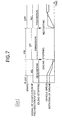
- Figs.1 to 7 show a first embodiment of the present invention, wherein Fig.1 is a view of an in-line type multi-cylinder engine, taken in an axial direction of a crankshaft; Fig.2 is an enlarged view of an essential portion of Fig.1; Fig.3 is a sectional view taken along a line 3-3 in Fig.2; Fig.4 is a block diagram of a control system for the engine; Fig.5 is a diagram for explaining conditions for stopping the idling of the engine; Fig.6 is a diagram for explaining conditions for restarting the engine; Fig.7 is a time chart for explaining the operation.
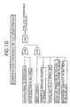
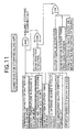
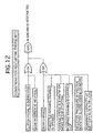
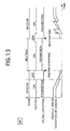
- Figs.8 to 13 show a second embodiment of the present invention, wherein Fig.8 is a block diagram of a control system for an engine; Fig.9 is a diagram for explaining conditions for continuing a decelerating fuel-cut operation; Fig.10 is a diagram for explaining conditions for canceling the fuel-cut operation; Fig.1 is a diagram for explaining conditions for stopping the idling of the engine; Fig.12 is a diagram for explaining conditions for restarting the engine; and Fig.13 is a time chart for explaining the operation according to the second embodiment.
- Figs.1 to 7 show a first embodiment of the present invention.
- an auxiliary part-mounting bracket 2 is fixed to a side of a cylinder block 1 of an in-line type multi-cylinder engine E mounted in a vehicle, and an oil pump 3 for a power-steering operation, an auto-tensioner 4, an alternator 5, an engine-cooling water pump 6 and an air-conditioning compressor 7 are fixed to the auxiliary part-mounting bracket 2.
- a single endless belt 15 is wound around a crank pulley 9 mounted at an end of a crankshaft 8 of the engine E (at an end opposite from a transmission), an oil pump pulley 10 mounted in the oil pump 3, a tensioner pulley 11 mounted on the auto-tensioner 4, an alternator pulley 12 mounted in the alternator 5, a water pump pulley 13 mounted in the water pump 6 and a compressor pulley 14 mounted in the compressor 7.
- a driving force of the crankshaft 8 is transmitted to the oil pump 3, the alternator 5, the water pump 6 and the compressor 7 by the endless belt 15, and a tension is provided to the endless belt 15 by the auto-tensioner 4.
- the tensioner pulley 11 and the water pump pulley 13 are driven by a back of the endless belt 15.
- the auxiliary parts 3 to 7 can be disposed closely to one another and compactly, and also the angle of winding of the endless belt 15 around each of the pulleys 10 to 14 can be ensured sufficiently to reliably drive the auxiliary parts 3 to 7.
- a cam shaft driving sprocket 21 and a balancer shaft driving sprocket 22 integrally formed with each other are fixed to the crankshaft 8 protruding from the cylinder block 1.
- An endless chain 23 wound around the cam shaft driving sprocket 21 and an endless chain 24 wound around the balancer shaft driving sprocket 22 are covered with a chain cover 25 fixed to the cylinder block 1.
- a boss 26 of the crank pulley 9 is fitted over and fixed by a bolt 27 to the end of the crankshaft 8 protruding from the chain cover 25.
- An annular peripheral wall 29 is integrally formed at an outer end of a disk-shaped sidewall 28 extending radially from the boss 26 of the crank pulley 9, and a pulley groove 29 1 is defined in an outer peripheral surface of the peripheral wall 29, so that the endless belt 15 is engaged in the pulley groove 29 1 .
- An annular space is defined within the crank pulley 9 and surrounded by the sidewall 28 and the peripheral wall 29, and a starter motor and generator M is accommodated in the space.
- the starter motor and generator M includes a plurality of permanent magnets 30 fixed along an inner peripheral surface of the peripheral wall 29 of the crank pulley 9.
- the permanent magnets 30 form a rotor of the starter motor and generator M.
- a plurality of coils 32 are wound around cores 31, respectively and fixed to an outer surface of the chain cover 25 by bolts 33 to surround the periphery of the crankshaft 8.
- the coils 32 form a stator of the starter motor and generator M, and have outer peripheral surfaces opposed to inner peripheral surfaces of the permanent magnets 30 with a small air gap left therebetween.
- a plate-shaped mounting bracket 34 is fixed to an outer surface of the chain cover 25 by three bolts 35, and three rotational speed sensors 36 are fixed to the mounting bracket 34 by bolts 37, respectively.
- a disk 39 fixed to the sidewall 28 of the crank pulley 9 by bolts 38 is provided at its outer periphery with a plurality of portions 40 to be detected by the rotational speed sensors 36.
- the crank pulley 9 only functions as a mere pulley.
- an attracting force and a repelling force are applied to the permanent magnets 30 by alternately exciting the coils 32 at a predetermined timing to rotate the crank pulley 9 to crank the crankshaft 8, thereby restarting the stopped engine E.
- the starter motor and generator M functions as a generator to generate a regenerative braking force.
- the starter motor and generator M for starting the engine E is accommodated in the crank pulley 9, and hence, the increases in sizes of the engine E and the transmission due to the mounting of the starter motor and generator M can be suppressed to the minimum, and the engine E and the transmission can easily be mounted in an engine room.
- the engine E is subjected to controls (an idle stopping control and a restarting control) for stopping the engine E automatically upon stopping of the vehicle in order to reduce the amount of fuel consumed and for restarting the engine E automatically upon starting of the vehicle.
- controls an idle stopping control and a restarting control
- a conventional starter motor mounted on the transmission.
- a general-purpose battery of 12 V for supplying electric power to a head light, an air-conditioner, an audio-set and the like is used for a power source for the conventional starter motor, but an exclusive battery of 36 V different from the general-purpose battery is used for the starter motor and generator M in this embodiment.
- a vehicle speed sensor S 1 for detecting a vehicle speed
- a throttle opening degree sensor S 2 for detecting a throttle opening degree
- an engine water-temperature sensor S 3 for detecting a temperature of water in the engine
- an engine intake air-temperature sensor S 4 for detecting a temperature of intake air in the engine
- an ignition switch S 5 an air-conditioner clutch switch S 6 for controlling the operation of an air-conditioner clutch
- a brake switch S 7 for detecting the operation of a brake pedal
- a shift range sensor S 8 for detecting a shift range in the automatic transmission
- a battery remaining-capacity sensor S 9 for detecting a remaining capacity of the battery for driving the starter motor and generator M
- a negative-pressure sensor S 10 for detecting a negative pressure in a vacuum booster for a brake device.
- Input to the electronic control unit U is a signal indicative of the completion of preparation of the CVT, namely, a signal indicating that the ratio of the CVT has been returned to a LOW range and a CVT starting clutch has been turned off, in addition to signals from the sensors and switches S 1 to S 10 .
- the decelerating fuel-cut control and the control of the stopping and starting of the engine E are carried out based on these signals.
- cut-off of the fuel supplied to the engine E (a decelerating fuel-cut operation) is carried out, leading to a reduction in amount of fuel consumed. If a driver does not have intent to stop the vehicle at that time, the supplying of the fuel is restarted so that the engine E is not stopped at the time when the engine speed is reduced to a fuel-cut canceling speed. If the driver has intent to stop the vehicle, the fuel-cut operation is continued to stop the engine E (stop the idling) in a case where predetermined conditions have been established, in order to avoid the consumption of the fuel due to an idle operation during stopping of the vehicle.
- Fig.5 shows conditions for stopping of the idling of the engine E. More specifically, the idling of the engine E is stopped without canceling of the fuel-cut operation, when the brake switch S 7 is in a turned-on state, the CVT is in a preparation-completed state (a state in which the ratio has been returned to LO and the starting clutch has been turned off) and in addition, the remaining capacity of the battery detected by the battery remaining-capacity sensor S 9 is 25 % or more to permit the driving of the starter motor and generator M; the temperature of water in the engine detected by the engine water-temperature sensor S 3 is 53°C or more and hence, the warming of the engine E has been completed; the temperature of an intake air in the engine detected by the engine intake-air temperature sensor S 4 ranges from 10°C to 40°C and hence, the battery can exhibit a performance sufficiently; the shift range detected by the shift range sensor S 8 is a "D" range or an "N" range; the throttle opening degree detected by the throttle opening degree sensor S 2 is a value indicative
- the reason why the stopping of the idling is not carried out before the vehicle speed once becomes 15 km/hr or more after restarting of the engine E is for the purpose of preventing the stopping of the idling from being carried out at a short time interval when the vehicle must be started and stopped repeatedly due to a traffic snarl or the like.
- Fig.6 shows conditions for restarting the engine E during stopping of the idling.
- Fig.7 shows one example of the above-described idling-stopping and restarting of the engine in a time chart.
- the following sensors and switches are connected to an electronic control unit U for governing the controlling of the stopping and starting of the engine E of the vehicle including the manual transmission: a vehicle speed sensor S 1 ; a throttle opening degree sensor S 2 ; an engine water-temperature sensor S 3 ; an engine intake air-temperature sensor S 4 ; an ignition switch S 5 ; an air-conditioner clutch switch S 6 ; a brake switch S 7 ; a gear position sensor S 8 ' for detecting a gear position of the manual transmission; a battery remaining capacity sensor S 9 ; a negative pressure sensor S 10 ; and a clutch switch S 11 for detecting the operation of a clutch pedal.
- a vehicle speed sensor S 1 a throttle opening degree sensor S 2 ; an engine water-temperature sensor S 3 ; an engine intake air-temperature sensor S 4 ; an ignition switch S 5 ; an air-conditioner clutch switch S 6 ; a brake switch S 7 ; a gear position sensor S 8 ' for detecting a gear position of the manual transmission; a battery remaining
- the electronic control unit U shown in Fig.8 is different from the electronic control unit shown in Fig.4 in points of that the gear position sensor S 8 ' for detecting the gear position of the manual transmission is connected thereto in place of the shift range sensor S 8 of the CVT, and that the clutch switch S 11 is connected thereto, and that a signal indicative of the completion of the preparation of the CVT is not input thereto.
- the other structure of the electronic control unit U shown in Fig.8 is the same as in the electronic control unit U shown in Fig.4.
- cut-off of the fuel supplied to the engine E (a decelerating fuel cut operation) is carried out to reduce the amount of fuel consumed.
- cut-off of the fuel supplied to the engine E (a decelerating fuel cut operation) is carried out to reduce the amount of fuel consumed.
- Fig.9 shows conditions for continuing the fuel-cut operation. More specifically, when the driver's intent to stop the vehicle is confirmed from conditions that the deceleration of the vehicle calculated from the vehicle speed detected by the vehicle speed sensor S 1 is 0.5 G or more, that the depression of the clutch pedal at an idling speed or less of the engine E has been detected by the clutch switch S 11 , that a gear position other than a first-gear position has been detected by the gear position sensor S 8 ', and that the depression of the brake pedal has been detected by the brake switch S 7 , the fuel-cut operation is continued, if the following preconditions are further established:
- the remaining capacity of the battery detected by the battery remaining-capacity sensor S 9 is 25 % or more to permit the driving of the starter motor and generator M; the temperature of water in the engine detected by the engine water-temperature sensor S 3 is 53° C or more to indicate that the warming of the engine E has been completed; the temperature of intake air in the engine detected by the engine intake air-temperature sensor S 4 ranges from 10°C to 40°C, whereby the battery can exhibit the performance sufficiently; the gear position detected by the gear position sensor S 8 ' is other than a reverse position; the throttle opening degree detected by the throttle opening degree sensor S 2 is a value indicative of a fully-closed state; the air-conditioner clutch switch S 6 has already been turned off, whereby there is not a possibility that the operation of the air-conditioner might be stopped by the stopping of the engine E; and the vehicle speed detected by the vehicle speed sensor S 1 is 30 km/hr or less, the fuel-cut operation is continued as it is.
- Fig.10 shows conditions for canceling the fuel-cut operation during continuation of the decelerating fuel-cut operation.
- Fig.11 shows conditions for carrying out the stopping of the idling to stop the engine E when the vehicle speed has been reduced to 0 (zero) by the continuation of the decelerating fuel-cut operation.
- the gear position is neutral, or the driver has depressed the clutch pedal to provide a gear position other than the first-gear position, and the vehicle speed detected by the vehicle speed sensor S 1 after restarting of the engine E has once become 3 km/hr or more, and it is confirmed that the driver does not have intent to start the vehicle, the stopping of the idling is continued, if the following preconditions are further established:
- the remaining capacity of the battery is 25 % or more, the temperature of water in the engine is 53°C or more, the temperature of intake air in the engine ranges from 10°C to 40°C, the gear position is other than the reverse position, the throttle opening degree is the value indicative of the fully-closed state, the air-conditioner clutch switch S 6 has already been turned off, and the vehicle speed is 3 km/hr or less, the stopping of the idling is carried out. It is the condition for stopping the idling that the vehicle speed once becomes 3 km/hr or more. Therefore, before the engine E is restarted to start the vehicle, the idling of the engine E is not stopped again.
- Fig.12 shows conditions for restarting the engine E during stopping of the idling.
- the clutch pedal has been depressed, or the gear position is neutral and in addition, when the gear change is detected, when the throttle opening degree has been brought into the value indicative of the opened state from the value indicative of the fully-closed state, when the vehicle speed has become 3 km/hr or more after the stopping of the vehicle, when a pumping braking has been conducted to consume the negative pressure in the vacuum booster, when the negative pressure in the vacuum booster for the brake device has become -250 mmHg or more in a gauge pressure, or when the remaining capacity of the battery is 25 % or less, the starter motor and generator M is driven to restart the engine E.
- Fig.13 shows one example of the above-described idling-stopping and restarting of the engine in a time chart.
- the CVT has been illustrated as the automatic transmission in the embodiments, but the present invention is applicable to a multi-stage automatic transmission.
- the engine-starting and stopping system is applicable to any automobile using as a power source an engine including a starter motor which also serves as a generator.
Landscapes
- Engineering & Computer Science (AREA)
- Power Engineering (AREA)
- Chemical & Material Sciences (AREA)
- Combustion & Propulsion (AREA)
- Mechanical Engineering (AREA)
- General Engineering & Computer Science (AREA)
- Control Of Vehicle Engines Or Engines For Specific Uses (AREA)
- Connection Of Motors, Electrical Generators, Mechanical Devices, And The Like (AREA)
- Output Control And Ontrol Of Special Type Engine (AREA)
Applications Claiming Priority (3)
| Application Number | Priority Date | Filing Date | Title |
|---|---|---|---|
| JP19023199A JP3777272B2 (ja) | 1999-07-05 | 1999-07-05 | 車両におけるエンジン始動/停止装置 |
| JP19023199 | 1999-07-05 | ||
| PCT/JP2000/004083 WO2001002721A1 (fr) | 1999-07-05 | 2000-06-22 | Dispositif de demarrage/arret d'un moteur de vehicule |
Publications (3)
| Publication Number | Publication Date |
|---|---|
| EP1209354A1 true EP1209354A1 (fr) | 2002-05-29 |
| EP1209354A4 EP1209354A4 (fr) | 2007-01-03 |
| EP1209354B1 EP1209354B1 (fr) | 2009-08-05 |
Family
ID=16254682
Family Applications (1)
| Application Number | Title | Priority Date | Filing Date |
|---|---|---|---|
| EP00940795A Expired - Lifetime EP1209354B1 (fr) | 1999-07-05 | 2000-06-22 | Dispositif de demarrage/arret d'un moteur de vehicule |
Country Status (13)
| Country | Link |
|---|---|
| US (1) | US6752112B1 (fr) |
| EP (1) | EP1209354B1 (fr) |
| JP (1) | JP3777272B2 (fr) |
| KR (1) | KR100532018B1 (fr) |
| CN (1) | CN1138062C (fr) |
| AT (1) | ATE438798T1 (fr) |
| AU (1) | AU759784B2 (fr) |
| BR (1) | BR0012229A (fr) |
| CA (1) | CA2378214C (fr) |
| DE (1) | DE60042692D1 (fr) |
| MX (1) | MXPA02000083A (fr) |
| TW (1) | TW487779B (fr) |
| WO (1) | WO2001002721A1 (fr) |
Cited By (4)
| Publication number | Priority date | Publication date | Assignee | Title |
|---|---|---|---|---|
| EP2568160A1 (fr) * | 2011-09-06 | 2013-03-13 | Mitsubishi Jidosha Kogyo K.K. | Dispositif de contrôle de véhicule |
| EP3035502A1 (fr) * | 2014-11-17 | 2016-06-22 | LG Electronics Inc. | Dispositif d' entraînement pour véhicule |
| EP2581286A3 (fr) * | 2011-10-12 | 2018-03-28 | Mitsubishi Jidosha Kogyo K.K. | Contrôleur de démarrage de moteur |
| EP2581285A3 (fr) * | 2011-10-12 | 2018-04-18 | Mitsubishi Jidosha Kogyo K.K. | Contrôleur de démarrage de moteur |
Families Citing this family (23)
| Publication number | Priority date | Publication date | Assignee | Title |
|---|---|---|---|---|
| JP4287065B2 (ja) * | 2001-02-14 | 2009-07-01 | 本田技研工業株式会社 | 自動二輪車 |
| JP4673489B2 (ja) * | 2001-02-22 | 2011-04-20 | 本田技研工業株式会社 | 車両用発電機 |
| US6910453B2 (en) * | 2003-03-04 | 2005-06-28 | Honda Motor Co., Ltd. | Automotive internal combustion engine control system |
| KR100560840B1 (ko) * | 2003-07-25 | 2006-03-13 | 신현오 | 자동차 안전출발 시스템 및 그 방법 |
| TWI341362B (en) * | 2004-02-18 | 2011-05-01 | Yamaha Motor Co Ltd | Saddle type vehicle, and engine controlling apparatus and idle stop canceling method for the saddle type vehicle |
| US7654238B2 (en) * | 2004-11-08 | 2010-02-02 | Ford Global Technologies, Llc | Systems and methods for controlled shutdown and direct start for internal combustion engine |
| TWI287513B (en) | 2005-12-19 | 2007-10-01 | Ind Tech Res Inst | Hybrid power system for vehicle |
| US8752449B2 (en) | 2007-05-08 | 2014-06-17 | Brooks Automation, Inc. | Substrate transport apparatus with multiple movable arms utilizing a mechanical switch mechanism |
| US9752615B2 (en) | 2007-06-27 | 2017-09-05 | Brooks Automation, Inc. | Reduced-complexity self-bearing brushless DC motor |
| US8283813B2 (en) | 2007-06-27 | 2012-10-09 | Brooks Automation, Inc. | Robot drive with magnetic spindle bearings |
| CN101790673B (zh) | 2007-06-27 | 2013-08-28 | 布鲁克斯自动化公司 | 用于自轴承电机的位置反馈 |
| US8823294B2 (en) | 2007-06-27 | 2014-09-02 | Brooks Automation, Inc. | Commutation of an electromagnetic propulsion and guidance system |
| KR20100056468A (ko) | 2007-07-17 | 2010-05-27 | 브룩스 오토메이션 인코퍼레이티드 | 챔버 벽들에 일체화된 모터들을 갖는 기판 처리 장치 |
| JP2009268266A (ja) * | 2008-04-25 | 2009-11-12 | Honda Motor Co Ltd | スタータモータ |
| US8494711B2 (en) * | 2010-01-04 | 2013-07-23 | GM Global Technology Operations LLC | Automated start-stop systems and methods for internal combustion engines |
| JP5601896B2 (ja) * | 2010-06-22 | 2014-10-08 | ダイハツ工業株式会社 | アイドルストップ車の駆動装置 |
| DE102010050123A1 (de) * | 2010-11-03 | 2012-05-03 | Audi Ag | Kraftfahrzeug mit einem Hybridantrieb und Verfahren zur Auswahl einer Elektromaschine und/oder eines Anlassers zum Anlassen eines Verbrennungsmotors |
| JP5429206B2 (ja) * | 2011-02-08 | 2014-02-26 | トヨタ自動車株式会社 | 車載内燃機関制御装置 |
| CN102678317A (zh) * | 2011-03-10 | 2012-09-19 | 湖南华强电气有限公司 | 一种汽车发动机 |
| CN103527339B (zh) * | 2013-09-16 | 2016-05-25 | 北京交通大学 | 一种控制柴油发动机快速启停的方法 |
| DE102014007435A1 (de) * | 2014-05-22 | 2015-11-26 | Man Truck & Bus Ag | Antriebsstrangmodul für ein Kraftfahrzeug |
| CN106194539B (zh) * | 2016-07-25 | 2019-04-26 | 潍柴动力股份有限公司 | 一种动力装置 |
| KR20190072926A (ko) * | 2017-12-18 | 2019-06-26 | 현대자동차주식회사 | Isg 기능을 포함하는 차량의 제어 방법 |
Family Cites Families (12)
| Publication number | Priority date | Publication date | Assignee | Title |
|---|---|---|---|---|
| US4013166A (en) * | 1975-11-10 | 1977-03-22 | Hydraulic Drives, Inc. | Hydraulic driven pulley for conveyors |
| JPS55166470A (en) * | 1979-06-08 | 1980-12-25 | Stanley Electric Co Ltd | Electric generator for engine |
| JPS58142378A (ja) | 1982-02-17 | 1983-08-24 | Ricoh Co Ltd | 電子写真装置 |
| JPH081445A (ja) * | 1994-06-23 | 1996-01-09 | Citizen Watch Co Ltd | 穴を形成するための棒材 |
| JP3368669B2 (ja) * | 1994-06-30 | 2003-01-20 | 株式会社デンソー | 車両用電動発電装置 |
| US5927240A (en) * | 1995-04-07 | 1999-07-27 | Maxon; Eric A. | Housing shared by vehicle component and disabling switch and decoder |
| JP3536627B2 (ja) * | 1997-11-18 | 2004-06-14 | トヨタ自動車株式会社 | 車両駆動装置 |
| JP2001065675A (ja) * | 1999-08-26 | 2001-03-16 | Honda Motor Co Ltd | 車両制御装置 |
| JP4064016B2 (ja) * | 1999-09-13 | 2008-03-19 | 本田技研工業株式会社 | 内燃機関の始動制御装置 |
| JP2001107769A (ja) * | 1999-10-04 | 2001-04-17 | Honda Motor Co Ltd | エンジン制御装置 |
| JP4066589B2 (ja) * | 2000-03-06 | 2008-03-26 | トヨタ自動車株式会社 | 内燃機関のアイドリングストップ制御装置およびこれを備える車両 |
| US6453864B1 (en) * | 2001-01-16 | 2002-09-24 | General Motors Corporation | Crankshaft rotation control in a hybrid electric vehicle |
-
1999
- 1999-07-05 JP JP19023199A patent/JP3777272B2/ja not_active Expired - Fee Related
-
2000
- 2000-06-22 BR BR0012229-7A patent/BR0012229A/pt not_active IP Right Cessation
- 2000-06-22 CA CA002378214A patent/CA2378214C/fr not_active Expired - Fee Related
- 2000-06-22 EP EP00940795A patent/EP1209354B1/fr not_active Expired - Lifetime
- 2000-06-22 DE DE60042692T patent/DE60042692D1/de not_active Expired - Lifetime
- 2000-06-22 WO PCT/JP2000/004083 patent/WO2001002721A1/fr not_active Ceased
- 2000-06-22 CN CNB008099286A patent/CN1138062C/zh not_active Expired - Fee Related
- 2000-06-22 AT AT00940795T patent/ATE438798T1/de not_active IP Right Cessation
- 2000-06-22 US US10/019,742 patent/US6752112B1/en not_active Expired - Fee Related
- 2000-06-22 AU AU55671/00A patent/AU759784B2/en not_active Ceased
- 2000-06-22 KR KR10-2001-7016851A patent/KR100532018B1/ko not_active Expired - Fee Related
- 2000-06-22 MX MXPA02000083A patent/MXPA02000083A/es active IP Right Grant
- 2000-07-04 TW TW089113230A patent/TW487779B/zh not_active IP Right Cessation
Cited By (4)
| Publication number | Priority date | Publication date | Assignee | Title |
|---|---|---|---|---|
| EP2568160A1 (fr) * | 2011-09-06 | 2013-03-13 | Mitsubishi Jidosha Kogyo K.K. | Dispositif de contrôle de véhicule |
| EP2581286A3 (fr) * | 2011-10-12 | 2018-03-28 | Mitsubishi Jidosha Kogyo K.K. | Contrôleur de démarrage de moteur |
| EP2581285A3 (fr) * | 2011-10-12 | 2018-04-18 | Mitsubishi Jidosha Kogyo K.K. | Contrôleur de démarrage de moteur |
| EP3035502A1 (fr) * | 2014-11-17 | 2016-06-22 | LG Electronics Inc. | Dispositif d' entraînement pour véhicule |
Also Published As
| Publication number | Publication date |
|---|---|
| WO2001002721A1 (fr) | 2001-01-11 |
| KR20020021149A (ko) | 2002-03-18 |
| AU759784B2 (en) | 2003-05-01 |
| KR100532018B1 (ko) | 2005-11-29 |
| TW487779B (en) | 2002-05-21 |
| MXPA02000083A (es) | 2002-08-30 |
| EP1209354B1 (fr) | 2009-08-05 |
| DE60042692D1 (de) | 2009-09-17 |
| AU5567100A (en) | 2001-01-22 |
| US6752112B1 (en) | 2004-06-22 |
| JP2001020838A (ja) | 2001-01-23 |
| CA2378214C (fr) | 2007-02-27 |
| CN1360665A (zh) | 2002-07-24 |
| ATE438798T1 (de) | 2009-08-15 |
| CA2378214A1 (fr) | 2001-01-11 |
| EP1209354A4 (fr) | 2007-01-03 |
| JP3777272B2 (ja) | 2006-05-24 |
| BR0012229A (pt) | 2002-03-26 |
| CN1138062C (zh) | 2004-02-11 |
Similar Documents
| Publication | Publication Date | Title |
|---|---|---|
| US6752112B1 (en) | Engine-starting and stopping system in vehicle | |
| US6763903B2 (en) | Automatic stop/ start-up controlling device of an engine | |
| JP3909641B2 (ja) | ハイブリッド車両の制御装置 | |
| CN103189620B (zh) | 车辆的控制装置 | |
| AU2018207288B2 (en) | Accessory belt drive system with multiple ratios and torque reversal | |
| US6418899B1 (en) | Electric drive arrangement for internal combustion engines in motor vehicles | |
| JP2003041967A (ja) | 内燃機関の自動停止制御装置 | |
| JP2004003434A (ja) | エンジン始動システム | |
| JP3011069B2 (ja) | 車両の制御装置 | |
| JP3214678B2 (ja) | 自動変速機付き車両の減速時におけるトルクコンバータ付設クラッチおよびエンジンの制御装置 | |
| JP4460813B2 (ja) | 自動車用の駆動力伝達列 | |
| JP2004239159A (ja) | 内燃機関始動装置 | |
| JP3719055B2 (ja) | 車両の制御装置 | |
| JP4027706B2 (ja) | エンジンの制御装置 | |
| JP2001020797A (ja) | 駆動装置 | |
| JP2004293327A (ja) | エンジンの自動停止装置 | |
| JP3747832B2 (ja) | エンジン自動停止機能付き車両 | |
| JP2004324588A (ja) | エンジン制御装置 | |
| JP2005113781A (ja) | エンジンの始動装置 | |
| JP2001298804A (ja) | 内燃機関の間欠運転機能を有する車両の補機駆動装置 | |
| JPH11294177A (ja) | 車両用補機駆動装置 | |
| JP3013728B2 (ja) | 車両用駆動装置の制御装置 | |
| JP2001020769A (ja) | 車両の制御装置 | |
| JPS6218104Y2 (fr) | ||
| JPS6040862Y2 (ja) | 自動車用エンジンの再始動装置 |
Legal Events
| Date | Code | Title | Description |
|---|---|---|---|
| PUAI | Public reference made under article 153(3) epc to a published international application that has entered the european phase |
Free format text: ORIGINAL CODE: 0009012 |
|
| 17P | Request for examination filed |
Effective date: 20020102 |
|
| AK | Designated contracting states |
Kind code of ref document: A1 Designated state(s): AT BE CH CY DE DK ES FI FR GB GR IE IT LI LU MC NL PT SE |
|
| A4 | Supplementary search report drawn up and despatched |
Effective date: 20061201 |
|
| 17Q | First examination report despatched |
Effective date: 20070323 |
|
| GRAP | Despatch of communication of intention to grant a patent |
Free format text: ORIGINAL CODE: EPIDOSNIGR1 |
|
| GRAS | Grant fee paid |
Free format text: ORIGINAL CODE: EPIDOSNIGR3 |
|
| GRAA | (expected) grant |
Free format text: ORIGINAL CODE: 0009210 |
|
| AK | Designated contracting states |
Kind code of ref document: B1 Designated state(s): AT BE CH CY DE DK ES FI FR GB GR IE IT LI LU MC NL PT SE |
|
| REG | Reference to a national code |
Ref country code: GB Ref legal event code: FG4D |
|
| REG | Reference to a national code |
Ref country code: CH Ref legal event code: EP |
|
| REG | Reference to a national code |
Ref country code: IE Ref legal event code: FG4D |
|
| REF | Corresponds to: |
Ref document number: 60042692 Country of ref document: DE Date of ref document: 20090917 Kind code of ref document: P |
|
| PG25 | Lapsed in a contracting state [announced via postgrant information from national office to epo] |
Ref country code: FI Free format text: LAPSE BECAUSE OF FAILURE TO SUBMIT A TRANSLATION OF THE DESCRIPTION OR TO PAY THE FEE WITHIN THE PRESCRIBED TIME-LIMIT Effective date: 20090805 Ref country code: AT Free format text: LAPSE BECAUSE OF FAILURE TO SUBMIT A TRANSLATION OF THE DESCRIPTION OR TO PAY THE FEE WITHIN THE PRESCRIBED TIME-LIMIT Effective date: 20090805 Ref country code: ES Free format text: LAPSE BECAUSE OF FAILURE TO SUBMIT A TRANSLATION OF THE DESCRIPTION OR TO PAY THE FEE WITHIN THE PRESCRIBED TIME-LIMIT Effective date: 20091116 Ref country code: SE Free format text: LAPSE BECAUSE OF FAILURE TO SUBMIT A TRANSLATION OF THE DESCRIPTION OR TO PAY THE FEE WITHIN THE PRESCRIBED TIME-LIMIT Effective date: 20090805 |
|
| NLV1 | Nl: lapsed or annulled due to failure to fulfill the requirements of art. 29p and 29m of the patents act | ||
| PG25 | Lapsed in a contracting state [announced via postgrant information from national office to epo] |
Ref country code: NL Free format text: LAPSE BECAUSE OF FAILURE TO SUBMIT A TRANSLATION OF THE DESCRIPTION OR TO PAY THE FEE WITHIN THE PRESCRIBED TIME-LIMIT Effective date: 20090805 |
|
| PG25 | Lapsed in a contracting state [announced via postgrant information from national office to epo] |
Ref country code: PT Free format text: LAPSE BECAUSE OF FAILURE TO SUBMIT A TRANSLATION OF THE DESCRIPTION OR TO PAY THE FEE WITHIN THE PRESCRIBED TIME-LIMIT Effective date: 20091205 |
|
| PG25 | Lapsed in a contracting state [announced via postgrant information from national office to epo] |
Ref country code: DK Free format text: LAPSE BECAUSE OF FAILURE TO SUBMIT A TRANSLATION OF THE DESCRIPTION OR TO PAY THE FEE WITHIN THE PRESCRIBED TIME-LIMIT Effective date: 20090805 |
|
| PLBE | No opposition filed within time limit |
Free format text: ORIGINAL CODE: 0009261 |
|
| STAA | Information on the status of an ep patent application or granted ep patent |
Free format text: STATUS: NO OPPOSITION FILED WITHIN TIME LIMIT |
|
| PG25 | Lapsed in a contracting state [announced via postgrant information from national office to epo] |
Ref country code: BE Free format text: LAPSE BECAUSE OF FAILURE TO SUBMIT A TRANSLATION OF THE DESCRIPTION OR TO PAY THE FEE WITHIN THE PRESCRIBED TIME-LIMIT Effective date: 20090805 |
|
| 26N | No opposition filed |
Effective date: 20100507 |
|
| PG25 | Lapsed in a contracting state [announced via postgrant information from national office to epo] |
Ref country code: GR Free format text: LAPSE BECAUSE OF FAILURE TO SUBMIT A TRANSLATION OF THE DESCRIPTION OR TO PAY THE FEE WITHIN THE PRESCRIBED TIME-LIMIT Effective date: 20091106 |
|
| PG25 | Lapsed in a contracting state [announced via postgrant information from national office to epo] |
Ref country code: MC Free format text: LAPSE BECAUSE OF NON-PAYMENT OF DUE FEES Effective date: 20100630 |
|
| REG | Reference to a national code |
Ref country code: CH Ref legal event code: PL |
|
| GBPC | Gb: european patent ceased through non-payment of renewal fee |
Effective date: 20100622 |
|
| REG | Reference to a national code |
Ref country code: FR Ref legal event code: ST Effective date: 20110228 |
|
| PG25 | Lapsed in a contracting state [announced via postgrant information from national office to epo] |
Ref country code: IT Free format text: LAPSE BECAUSE OF FAILURE TO SUBMIT A TRANSLATION OF THE DESCRIPTION OR TO PAY THE FEE WITHIN THE PRESCRIBED TIME-LIMIT Effective date: 20090805 |
|
| PG25 | Lapsed in a contracting state [announced via postgrant information from national office to epo] |
Ref country code: CH Free format text: LAPSE BECAUSE OF NON-PAYMENT OF DUE FEES Effective date: 20100630 Ref country code: LI Free format text: LAPSE BECAUSE OF NON-PAYMENT OF DUE FEES Effective date: 20100630 Ref country code: IE Free format text: LAPSE BECAUSE OF NON-PAYMENT OF DUE FEES Effective date: 20100622 |
|
| PG25 | Lapsed in a contracting state [announced via postgrant information from national office to epo] |
Ref country code: FR Free format text: LAPSE BECAUSE OF NON-PAYMENT OF DUE FEES Effective date: 20100630 |
|
| PG25 | Lapsed in a contracting state [announced via postgrant information from national office to epo] |
Ref country code: GB Free format text: LAPSE BECAUSE OF NON-PAYMENT OF DUE FEES Effective date: 20100622 |
|
| PG25 | Lapsed in a contracting state [announced via postgrant information from national office to epo] |
Ref country code: CY Free format text: LAPSE BECAUSE OF FAILURE TO SUBMIT A TRANSLATION OF THE DESCRIPTION OR TO PAY THE FEE WITHIN THE PRESCRIBED TIME-LIMIT Effective date: 20090805 |
|
| PG25 | Lapsed in a contracting state [announced via postgrant information from national office to epo] |
Ref country code: LU Free format text: LAPSE BECAUSE OF NON-PAYMENT OF DUE FEES Effective date: 20100622 |
|
| REG | Reference to a national code |
Ref country code: DE Ref legal event code: R084 Ref document number: 60042692 Country of ref document: DE Effective date: 20140204 |
|
| PGFP | Annual fee paid to national office [announced via postgrant information from national office to epo] |
Ref country code: DE Payment date: 20140618 Year of fee payment: 15 |
|
| REG | Reference to a national code |
Ref country code: DE Ref legal event code: R119 Ref document number: 60042692 Country of ref document: DE |
|
| PG25 | Lapsed in a contracting state [announced via postgrant information from national office to epo] |
Ref country code: DE Free format text: LAPSE BECAUSE OF NON-PAYMENT OF DUE FEES Effective date: 20160101 |