EP1209385A2 - Bürstendichtungsanordnung - Google Patents
Bürstendichtungsanordnung Download PDFInfo
- Publication number
- EP1209385A2 EP1209385A2 EP01309952A EP01309952A EP1209385A2 EP 1209385 A2 EP1209385 A2 EP 1209385A2 EP 01309952 A EP01309952 A EP 01309952A EP 01309952 A EP01309952 A EP 01309952A EP 1209385 A2 EP1209385 A2 EP 1209385A2
- Authority
- EP
- European Patent Office
- Prior art keywords
- brush
- holding portion
- seal device
- free end
- gap
- Prior art date
- Legal status (The legal status is an assumption and is not a legal conclusion. Google has not performed a legal analysis and makes no representation as to the accuracy of the status listed.)
- Granted
Links
- 239000013013 elastic material Substances 0.000 claims 1
- 239000012530 fluid Substances 0.000 abstract description 26
- 238000007789 sealing Methods 0.000 abstract description 12
- 238000011144 upstream manufacturing Methods 0.000 description 7
- 230000002093 peripheral effect Effects 0.000 description 6
- 230000000694 effects Effects 0.000 description 3
- 239000000463 material Substances 0.000 description 3
- 239000002184 metal Substances 0.000 description 3
- 229920003002 synthetic resin Polymers 0.000 description 3
- 239000000057 synthetic resin Substances 0.000 description 3
- 239000002131 composite material Substances 0.000 description 2
- 238000003466 welding Methods 0.000 description 2
- 239000000919 ceramic Substances 0.000 description 1
- 229910010293 ceramic material Inorganic materials 0.000 description 1
- 238000010276 construction Methods 0.000 description 1
- 239000005060 rubber Substances 0.000 description 1
- 230000003746 surface roughness Effects 0.000 description 1
Images



Classifications
-
- F—MECHANICAL ENGINEERING; LIGHTING; HEATING; WEAPONS; BLASTING
- F16—ENGINEERING ELEMENTS AND UNITS; GENERAL MEASURES FOR PRODUCING AND MAINTAINING EFFECTIVE FUNCTIONING OF MACHINES OR INSTALLATIONS; THERMAL INSULATION IN GENERAL
- F16J—PISTONS; CYLINDERS; SEALINGS
- F16J15/00—Sealings
- F16J15/16—Sealings between relatively-moving surfaces
- F16J15/32—Sealings between relatively-moving surfaces with elastic sealings, e.g. O-rings
- F16J15/3284—Sealings between relatively-moving surfaces with elastic sealings, e.g. O-rings characterised by their structure; Selection of materials
- F16J15/3288—Filamentary structures, e.g. brush seals
Definitions
- the present invention relates to a brush seal device having a brush for sealing a gap between two parts that move relative to each other (that make rotational movements, reciprocating movements, or the like). More particularly, the present invention relates to a brush seal device for sealing a gap between two parts which are opposed to each other and one of which is movable.
- a brush seal device as shown in Fig. 9 is based on a generally known art.
- a brush seal 11 is composed of a brush 12 and a holding portion 14.
- the brush 12 is formed of thin bristles 13 made from a highly rigid material such as metal, synthetic resin, ceramics, composite material, or the like.
- the thin bristles 13 are disposed in a wall shape with a certain thickness.
- the holding portion 14 is composed of a back plate 15 and a side plate 16, which hold and clamp the brush 12 therebetween.
- the holding portion 14 of the brush seal 11 is secured to one (a fixed body not shown in the drawing) of two parts that move relative to each other (e.g. that make rotational movements), and a free end of the brush 12 is in contact with the other part 20 (a rotor).
- the free end of the brush 12 is contiguous to the other part 20 and spaced apart therefrom by a narrow gap, whereby the gap between the two parts that move relative to each other is sealed (see Figs. 9 to 11).
- the entire brush 12 escapes while deflecting radially in accordance with the movement of the other part 20. It is thus possible to prevent the free end portion of the brush 12 from wearing down and prevent the amount of leakage of sealed fluid from increasing.
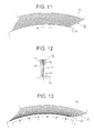
- the brush 12 is pressed hard against the back plate 15 due to a differential pressure between upstream and downstream pressures. Therefore, if the other part 20 is off-centered during rotation or is deformed due to its rotation or if the gap between one part (the fixed body) and the other part 20 undergoes a change ascribable to a relative dimensional difference between the two parts as a result of a difference in thermal expansion coefficient therebetween, a frictional resistance between the brush 12 and the back plate 15 and a frictional resistance of the thin bristles 13 of the brush 12 prevent the brush 12 from deflecting radially and escaping. Hence, the free end portion of the brush 12 wears down (see Figs. 12 and 13).
- the brush 12 is held while deflecting toward the back plate 15 due to the frictional resistance between the brush 12 and the back plate 15 and the frictional resistance of the thin bristles 13 of the brush 12. Therefore, the brush 12 cannot return from its deflected state to its original state. Hence, the gap between the free end portion of the brush 12 and the other part 20 increases to the extent of causing leakage (see Figs. 14 and 15).
- the brush 12 is free in a region affected by sealed fluid, the spaces among the thin bristles 13 in the region constitute passages into which sealed fluid flows and from which sealed fluid leaks (see Fig. 10).
- the present invention has been made as a solution to the conventional problems as described above. It is an object of the present invention to allow the brush to escape while deflecting radially in accordance with the movement of the other part if the other part is off-centered during its rotation or is deformed due to its rotation or if the gap between one part (the fixed body) and the other part undergoes a change ascribable to a relative dimensional difference between the two parts as a result of a difference in thermal expansion coefficient therebetween.
- the brush seal device of the present invention has a brush and a holding portion.
- the brush has a plurality of bristles disposed in a mural manner.
- the holding portion holds one end side of the brush.
- the holding portion is secured to one of two parts that move relative to each other, and a free end portion of the brush is disposed in contact with or contiguous to the other part.
- An elastically deformable elastic portion for sealing is provided between opposed faces of the holding portion and the brush. The brush is pressed toward the holding portion due to an elastic force of the elastic portion so that the gap between the brush and the holding portion is sealed. Thus, sealed fluid is prevented from entering the gap between the brush and the holding portion.
- the brush seal device of the present invention is based on the aspect as described above, the brush is pressed against the face of the holding portion which is opposed to the brush due to the elastic force of the elastic portion, so that the bristles of the brush are in close contact with one another.
- sealed fluid can be prevented from entering spaces among the bristles. Therefore, the brush can deflect in accordance with the movement of the other part without being immobilized by a pressure of sealed fluid entering those spaces.
- the brush can return quickly from its deflected state to its original state.
- the elastic portion for sealing seals the gap between the brush and the holding portion, it is possible to prevent sealed fluid from entering the gap between the brush and the holding portion and to prevent the brush from being exposed to a differential pressure between upstream and downstream pressures. As a result, the brush is not immobilized by being pressed against the holding portion due to such a differential pressure. Thus, it becomes easier for the brush to deflect in accordance with the movement of the other part or even to return from its deflected state to its original state.
- Fig. 1 is a sectional view of a brush seal device according to a preferred embodiment of the present invention, showing a state in which the brush seal device is fitted to the other part (rotor).
- Fig. 2 is a plan view of a brush and a holding portion when viewed from the inside diameter side of the brush seal device shown in Fig. 1.
- the brush seal device 1 mainly includes a brush 2 formed by disposing bristles 3 in a wall shape with a certain thickness, a holding portion 4 for holding a fitting portion at one end of the brush 2, and an elastic portion 9 interposed between opposed faces of the brush 2 and the holding portion 4.
- the bristles 3 of the brush 2 are made from a highly rigid material such as metal, synthetic resin, ceramic material, composite material, or the like.
- the bristles 3 are disposed in a wall shape with a certain thickness so that a gap to be sealed can be shut off.
- the brush 2 is formed into a shape suited for a location to be sealed. As a whole, the brush 2 assumes an annular, semi-annular, or plate-like shape, etc. Because the location to be sealed in the first preferred embodiment is a gap between two parts that rotate relative to each other, the brush 2 is formed into an annular shape correspondingly. As shown in Fig. 11, the bristles 3 are inclined with respect to a radial direction. This inclination is directed in a direction in which the other part 20 (10) rotates as indicated by an arrow in Fig. 11.
- the holding portion 4 is formed into a shape corresponding to the shape of the brush 2 and thus into an annular, semi-annular, or plate-like shape, etc. Because the location to be sealed in the first preferred embodiment is a gap between two parts that rotate relative to each other, the holding portion 4 is formed into an annular shape just like the brush 2.
- the holding portion 4 is composed of an annular back plate 5 and an annular side plate 6, which is integrally attached to one side of the back plate 5 by a connecting means such as welding, bolts, or the like.
- the back plate 5 and the side plate 6 are substantially equal in inner diameter and outer diameter.
- a step portion 7 designed to create a gap between the brush 2 and the side plate 6 is formed in the side plate 6 in its face opposed to the back plate 5, in such a manner as to form an annular space stretching along the entire circumference.
- a mounting groove 8 for mounting the elastic portion 9 is formed in an inner peripheral edge portion of the step portion 7 along its peripheral face.
- the mounting groove 8 is rectangular in cross-section.
- the elastic portion 9, which will be described later, is fitted into the mounting groove 8.
- the brush 2 is held between the back plate 5 and the side plate 6. In this case, while one side of the brush 2 is joined with one side of the back plate 5, the brush 2 is clamped in its region relatively close to its outer diameter side between the back plate 5 and the side plate 6.
- the brush 2 is integrated with the back plate 5 and the side plate 6.
- An outer diameter end portion of the brush 2 is integrally connected with the outer peripheral portions of the back plate 5 and the side plate 6 by welding or the like.
- the inner peripheral face of the brush 2 is formed in such a manner as to protrude from the inner peripheral faces of the back plate 5 and the side plate 6, and is smaller in diameter than the inner peripheral faces of the back plate 5 and the side plate 6 by a preset length. The free end portion of the brush 2 thus protruding performs a sealing function.
- the elastic portion 9 is a ring-like member having a generally circular cross-sectional shape and is made from an elastically deformable material such as rubber, synthetic resin, metal, or the like. Due to an elastic force of the elastic portion 9, the bristles 3 on the side of the free end portion of the brush 2 having the sealing function are in close contact with one another while being held toward the back plate 5. Also, the elastic portion 9 seals a gap between the brush 2 and the side plate 6 on its inner diameter side. In this construction, the surface roughness values of the opposed faces of the back plate 5 and the side plate 6 with which the brush 2 is in contact, the hardness of the elastic portion 9, and the pressing load of the elastic portion 9, and the like are set such that the brush 2 can move in response to abutment on the rotor.
- the brush seal device 1 is designed such that the holding portion 4 is secured to one part (a housing that is not shown in the drawings for this embodiment) of two parts that move relative to each other and that the free end portion of the brush 2 is in contact with the other part 10 (the rotor in this embodiment).
- the holding portion 4 is secured to one part (a housing that is not shown in the drawings for this embodiment) of two parts that move relative to each other and that the free end portion of the brush 2 is in contact with the other part 10 (the rotor in this embodiment).
- the brush 2 is pressed against the other part 10 and thus is urged to deflect radially and escape.
- the elastic portion 9 is interposed between the brush 2 and the side plate 6 and thus seals the gap therebetween.
- sealed fluid is prevented from entering the gap between the brush 2 and the side plate 6 and from exposing the brush 2 to a differential pressure, namely, a difference between upstream and downstream pressures. It is thus possible to prevent the brush 2 from being pressed hard against the back plate 5 due to such a differential pressure.
- a differential pressure namely, a difference between upstream and downstream pressures.
- the brush 2 is not exposed to a differential pressure between upstream and downstream pressures. Hence, the brush 2 is prevented from deflecting due to such a differential pressure when it is held by the back plate 5. Thus, the brush 2 is allowed to move freely without hindrance.
- the brush 2 can return from its deflected state to its original state. Therefore, it is possible to effectively prevent the gap between the free end portion of the brush 2 and the other part 10 from increasing to the extent of increasing the amount of leakage of sealed fluid.
- the brush 2 is held toward the back plate 5 due to an elastic force of the elastic portion 9 so that the bristles 3 are in close contact with one another. Therefore, sealed fluid does not enter the spaces among the bristles 3. Thus, the brush 2 can be prevented from being immobilized by being pressed hard against the other part 10 due to a pressure of sealed fluid entering those spaces.
- the brush 2 can deflect in accordance with the movement of the other part 10 or even return from its deflected state to its original state.
- the free end portion of the brush 2 can be prevented from wearing down.
- Figs. 3 to 8 show the brush seal device 1 according to other embodiments of the present invention.
- Fig. 3 shows the second embodiment of the present invention.
- the elastic portion 9 mounted in the mounting groove 8 is formed into a generally quadrate (rectangular) shape.
- Fig. 4 shows the third embodiment of the present invention.
- the elastic portion 9 mounted in the mounting groove 8 shown in Fig. 4 has a ring-like cross-sectional shape.
- Fig. 5 shows the fourth embodiment of the present invention.
- the elastic portion 9 mounted in the mounting groove 8 shown in Fig. 5 has a U-shaped cross-section.
- Fig. 6 shows the fifth embodiment of the present invention.
- the elastic portion 9 mounted in the mounting groove 8 shown in Fig. 6 has an E-shaped cross-section.
- Fig. 7 shows the sixth embodiment of the present invention.
- the elastic portion 9 mounted in the mounting groove 8 shown in Fig. 7 has an L-shaped cross-section. Further, the mounting groove 8 is formed into the shape of I. A mounting portion of the elastic portion 9 is press-fitted into and secured to the mounting groove 8, and a free end portion of the elastic portion 9 is joined with the brush 2 so that the back plate 5 holds the brush 2.
- Fig. 8 shows the seventh embodiment of the present invention.
- the elastic portion 9 mounted in the mounting groove 8 shown in Fig. 8 has an L-shaped cross-section. Further, the mounting groove 8 is formed in a stepped manner in an end face of the side plate 6. The mounting portion of the elastic portion 9 is fitted into and attached to the mounting groove 8, and the free end portion of the elastic portion 9 is joined with the brush 2 so that the brush 2 is joined with the back plate 5.
- the second to seventh embodiments are also designed such that the elastic portion 9 is interposed between the brush 2 and the side plate 6 and thus seals the gap created therebetween. Therefore, sealed fluid is prevented from reaching the gap between the brush 2 and the side plate 6 and from directly exposing the brush 2 to a differential pressure, namely, a difference between upstream and downstream pressures.
- a differential pressure namely, a difference between upstream and downstream pressures.
- the brush 2 is prevented from being pressed hard against the back plate 5 due to the differential pressure to such an extent that the operation of the brush 2 corresponding to the abutment on the other part 10 is hindered.
- the brush 2 is not exposed to a differential pressure between upstream and downstream pressures. It is thus possible to prevent the back plate 5 from holding the brush 2 in its deflected state caused by the differential pressure. Even if the other part 10 abuts on the brush 2, the brush 2 can move without hindrance. Hence, the brush 2 can return quickly from its deflected state to its original state, whereby the amount of leakage of sealed fluid can be prevented effectively from increasing as a result of an increase in the gap between the free end portion of the brush 2 and the other part 10.
- the brush 2 since the brush 2 is held by the back plate 5 due to an elastic force of the elastic portion 9 so that the bristles 3 are in close contact with one another, sealed fluid is prevented from entering the spaces among the bristles 3.
- the inconvenience of immobility of the brush 2, which would be caused if sealed fluid entered the spaces among the bristles 3 and pressed the brush 2 hard against the other part 10, can be prevented.
- the brush 2 can deflect in accordance with the movement of the other part 10 and, on the contrary, can return quickly from its deflected state to its original state. Therefore, the free end portion of the brush 2 can be prevented effectively from wearing down.
- the elastic portion 9 has a circular, rectangular, ring-like, U-shaped, E-shaped, or L-shaped cross-section etc. in the embodiments described above, the cross-sectional shape of the elastic portion 9 should not be limited thereto. As long as the same operation and effect as described above can be achieved, the elastic portion 9 may assume any cross-sectional shape. It is to be noted herein that the elastic portion 9 has the functions of holding the bristles 3 in light touch with the back plate 5 and sealing the side of the mounting portion of the brush 2 between the back plate 5 and the side plate 6 so as to prevent entrance of sealed fluid.
- the brush 2 can be held effectively by the holding portion 4 due to an elastic force of the elastic portion 9.
- the gap between the brush 2 and the holding portion 4 is sealed so as to prevent sealed fluid from entering the gap between the brush 2 and the holding portion 4, whereby it becomes possible to prevent the brush 2 from being exposed to a differential pressure between upstream and downstream pressures.
- the inconvenience of immobility of the brush 2, which would be caused if the brush 2 were pressed hard against the holding portion 4 due to the differential pressure can also be prevented effectively.
- the brush 2 can deflect in accordance with the movement of the other part 10 or even return quickly from its deflected state.
- the free end portion of the brush 2, which is in press-contact with the other part 10, can be prevented effectively from wearing down.
- the brush 2 can deflect in accordance with the movement of the other part 10 and can return quickly from its deflected state to its original state, the free end portion of the brush 2 can be prevented effectively from wearing down.
Landscapes
- Engineering & Computer Science (AREA)
- General Engineering & Computer Science (AREA)
- Mechanical Engineering (AREA)
- Sealing Devices (AREA)
- Brushes (AREA)
Applications Claiming Priority (2)
| Application Number | Priority Date | Filing Date | Title |
|---|---|---|---|
| JP2000359129A JP2002159343A (ja) | 2000-11-27 | 2000-11-27 | ブラシ型シール装置 |
| JP2000359129 | 2000-11-27 |
Publications (3)
| Publication Number | Publication Date |
|---|---|
| EP1209385A2 true EP1209385A2 (de) | 2002-05-29 |
| EP1209385A3 EP1209385A3 (de) | 2003-10-29 |
| EP1209385B1 EP1209385B1 (de) | 2005-11-02 |
Family
ID=18830938
Family Applications (1)
| Application Number | Title | Priority Date | Filing Date |
|---|---|---|---|
| EP01309952A Expired - Lifetime EP1209385B1 (de) | 2000-11-27 | 2001-11-27 | Bürstendichtungsanordnung |
Country Status (4)
| Country | Link |
|---|---|
| US (1) | US6655692B2 (de) |
| EP (1) | EP1209385B1 (de) |
| JP (1) | JP2002159343A (de) |
| DE (1) | DE60114548T2 (de) |
Cited By (2)
| Publication number | Priority date | Publication date | Assignee | Title |
|---|---|---|---|---|
| EP2042788A1 (de) | 2007-09-28 | 2009-04-01 | Honeywell International Inc. | Fingerdichtungsanordnung mit verringerter Druckbelastung |
| CN102581486A (zh) * | 2012-02-06 | 2012-07-18 | 江苏透平密封高科技有限公司 | 刷式密封激光渗透打点焊接方法 |
Families Citing this family (12)
| Publication number | Priority date | Publication date | Assignee | Title |
|---|---|---|---|---|
| US7413194B2 (en) * | 2004-10-28 | 2008-08-19 | Rolls-Royce Plc | Pressure balanced annular seal |
| US20060249911A1 (en) * | 2005-05-04 | 2006-11-09 | General Electric Company | Abradable and/or abrasive coating and brush seal configuration |
| GB0705671D0 (en) * | 2007-03-24 | 2007-05-02 | Cross Mfg Co 1938 Ltd | A seal |
| US20080296846A1 (en) * | 2007-05-29 | 2008-12-04 | Eaton Corporation | Static outside diameter brush seal assembly |
| DE102008006485A1 (de) * | 2008-01-29 | 2009-07-30 | Mtu Aero Engines Gmbh | Bürstendichtung und Verfahren zur Montage einer Bürstendichtung |
| US8632074B2 (en) * | 2008-07-14 | 2014-01-21 | Cross Manufacturing Company (1938) Limited | Method of forming a brush seal |
| US9206904B2 (en) | 2010-07-08 | 2015-12-08 | Siemens Energy, Inc. | Seal including flexible seal strips |
| US8690158B2 (en) * | 2010-07-08 | 2014-04-08 | Siemens Energy, Inc. | Axially angled annular seals |
| US8382120B2 (en) * | 2010-08-31 | 2013-02-26 | General Electric Company | Method and apparatus for compliant plate seals |
| JP5595259B2 (ja) * | 2010-12-27 | 2014-09-24 | 三菱重工業株式会社 | 軸シール装置及びこれを備える回転機械 |
| CN105562885B (zh) * | 2016-02-19 | 2017-11-10 | 江苏拓平密封科技有限公司 | 基于钴粉填缝及3d打印技术的刷式密封焊接方法 |
| US10844741B2 (en) | 2016-11-21 | 2020-11-24 | Pratt & Whitney Canada Corp. | Brush seal assembly and method |
Family Cites Families (5)
| Publication number | Priority date | Publication date | Assignee | Title |
|---|---|---|---|---|
| GB2250790B (en) * | 1990-12-12 | 1994-04-27 | Rolls Royce Plc | Brush seal |
| GB2258277B (en) * | 1991-07-29 | 1995-02-22 | Europ Gas Turbines Ltd | Brush seals |
| US5568931A (en) * | 1992-08-20 | 1996-10-29 | General Electric Company | Brush seal |
| GB9525212D0 (en) * | 1995-12-09 | 1996-02-07 | Rolls Royce Plc | Brush seal |
| GB9801864D0 (en) * | 1998-01-30 | 1998-03-25 | Rolls Royce Plc | A seal arrangement |
-
2000
- 2000-11-27 JP JP2000359129A patent/JP2002159343A/ja active Pending
-
2001
- 2001-11-26 US US09/991,637 patent/US6655692B2/en not_active Expired - Lifetime
- 2001-11-27 DE DE60114548T patent/DE60114548T2/de not_active Expired - Lifetime
- 2001-11-27 EP EP01309952A patent/EP1209385B1/de not_active Expired - Lifetime
Non-Patent Citations (1)
| Title |
|---|
| None |
Cited By (3)
| Publication number | Priority date | Publication date | Assignee | Title |
|---|---|---|---|---|
| EP2042788A1 (de) | 2007-09-28 | 2009-04-01 | Honeywell International Inc. | Fingerdichtungsanordnung mit verringerter Druckbelastung |
| CN102581486A (zh) * | 2012-02-06 | 2012-07-18 | 江苏透平密封高科技有限公司 | 刷式密封激光渗透打点焊接方法 |
| CN102581486B (zh) * | 2012-02-06 | 2014-08-20 | 江苏透平密封高科技有限公司 | 刷式密封激光渗透打点焊接方法 |
Also Published As
| Publication number | Publication date |
|---|---|
| US20020063391A1 (en) | 2002-05-30 |
| EP1209385B1 (de) | 2005-11-02 |
| JP2002159343A (ja) | 2002-06-04 |
| EP1209385A3 (de) | 2003-10-29 |
| DE60114548T2 (de) | 2006-07-20 |
| US6655692B2 (en) | 2003-12-02 |
| DE60114548D1 (de) | 2005-12-08 |
Similar Documents
| Publication | Publication Date | Title |
|---|---|---|
| EP1209385B1 (de) | Bürstendichtungsanordnung | |
| JP4012763B2 (ja) | ロッド又はピストンの一次シール部 | |
| US7055828B2 (en) | Shaft seal | |
| EP1245875B1 (de) | Bürstendichtung | |
| JP5604530B2 (ja) | 回転シール装置 | |
| EP1541908A1 (de) | Dichtungsring | |
| JP5252878B2 (ja) | 回転軸シール | |
| JP2001263500A (ja) | リップ型シール | |
| WO2010061670A1 (ja) | リップタイプシール | |
| KR960000665B1 (ko) | 밀봉링 지지조립체 및 지지방법 | |
| GB2213236A (en) | Metallic seal for high performance butterfly or ball valve | |
| US20090166977A1 (en) | Seal | |
| JP2001263499A (ja) | リップ型シール | |
| CN101228379B (zh) | 机械密封装置 | |
| EP1203906A2 (de) | Bürstendichtung | |
| JP2003214541A (ja) | シール装置 | |
| JP4396790B2 (ja) | オイルシール | |
| JPH08135795A (ja) | シール装置 | |
| JP5520556B2 (ja) | 密封装置 | |
| EP1203905A2 (de) | Bürstendichtung | |
| JP3564932B2 (ja) | 密封装置 | |
| JP3155483B2 (ja) | バルブステムシール | |
| JPH07243536A (ja) | フローティングリングシール | |
| JP2008175322A (ja) | シャフトシール装置 | |
| JPH026303Y2 (de) |
Legal Events
| Date | Code | Title | Description |
|---|---|---|---|
| PUAI | Public reference made under article 153(3) epc to a published international application that has entered the european phase |
Free format text: ORIGINAL CODE: 0009012 |
|
| AK | Designated contracting states |
Kind code of ref document: A2 Designated state(s): AT BE CH CY DE DK ES FI FR GB GR IE IT LI LU MC NL PT SE TR |
|
| AX | Request for extension of the european patent |
Free format text: AL;LT;LV;MK;RO;SI |
|
| PUAL | Search report despatched |
Free format text: ORIGINAL CODE: 0009013 |
|
| AK | Designated contracting states |
Kind code of ref document: A3 Designated state(s): AT BE CH CY DE DK ES FI FR GB GR IE IT LI LU MC NL PT SE TR |
|
| AX | Request for extension of the european patent |
Extension state: AL LT LV MK RO SI |
|
| 17P | Request for examination filed |
Effective date: 20040413 |
|
| AKX | Designation fees paid |
Designated state(s): DE FR GB |
|
| 17Q | First examination report despatched |
Effective date: 20040915 |
|
| GRAP | Despatch of communication of intention to grant a patent |
Free format text: ORIGINAL CODE: EPIDOSNIGR1 |
|
| GRAS | Grant fee paid |
Free format text: ORIGINAL CODE: EPIDOSNIGR3 |
|
| GRAA | (expected) grant |
Free format text: ORIGINAL CODE: 0009210 |
|
| AK | Designated contracting states |
Kind code of ref document: B1 Designated state(s): DE FR GB |
|
| REG | Reference to a national code |
Ref country code: GB Ref legal event code: FG4D |
|
| REF | Corresponds to: |
Ref document number: 60114548 Country of ref document: DE Date of ref document: 20051208 Kind code of ref document: P |
|
| ET | Fr: translation filed | ||
| PLBE | No opposition filed within time limit |
Free format text: ORIGINAL CODE: 0009261 |
|
| STAA | Information on the status of an ep patent application or granted ep patent |
Free format text: STATUS: NO OPPOSITION FILED WITHIN TIME LIMIT |
|
| 26N | No opposition filed |
Effective date: 20060803 |
|
| PGFP | Annual fee paid to national office [announced via postgrant information from national office to epo] |
Ref country code: FR Payment date: 20081112 Year of fee payment: 8 |
|
| REG | Reference to a national code |
Ref country code: FR Ref legal event code: ST Effective date: 20100730 |
|
| PG25 | Lapsed in a contracting state [announced via postgrant information from national office to epo] |
Ref country code: FR Free format text: LAPSE BECAUSE OF NON-PAYMENT OF DUE FEES Effective date: 20091130 |
|
| PGFP | Annual fee paid to national office [announced via postgrant information from national office to epo] |
Ref country code: DE Payment date: 20201118 Year of fee payment: 20 Ref country code: GB Payment date: 20201118 Year of fee payment: 20 |
|
| REG | Reference to a national code |
Ref country code: DE Ref legal event code: R071 Ref document number: 60114548 Country of ref document: DE |
|
| REG | Reference to a national code |
Ref country code: GB Ref legal event code: PE20 Expiry date: 20211126 |
|
| PG25 | Lapsed in a contracting state [announced via postgrant information from national office to epo] |
Ref country code: GB Free format text: LAPSE BECAUSE OF EXPIRATION OF PROTECTION Effective date: 20211126 |