EP1209442A2 - Mesure automatique de la rayon de courbure - Google Patents
Mesure automatique de la rayon de courbure Download PDFInfo
- Publication number
- EP1209442A2 EP1209442A2 EP01309759A EP01309759A EP1209442A2 EP 1209442 A2 EP1209442 A2 EP 1209442A2 EP 01309759 A EP01309759 A EP 01309759A EP 01309759 A EP01309759 A EP 01309759A EP 1209442 A2 EP1209442 A2 EP 1209442A2
- Authority
- EP
- European Patent Office
- Prior art keywords
- radius
- curvature
- cavity
- radiant energy
- interferometer
- Prior art date
- Legal status (The legal status is an assumption and is not a legal conclusion. Google has not performed a legal analysis and makes no representation as to the accuracy of the status listed.)
- Withdrawn
Links
- 238000005259 measurement Methods 0.000 title claims abstract description 81
- 230000003287 optical effect Effects 0.000 claims abstract description 84
- 238000012544 monitoring process Methods 0.000 claims abstract description 13
- 230000001427 coherent effect Effects 0.000 claims abstract description 7
- 230000005855 radiation Effects 0.000 claims abstract description 6
- 230000008859 change Effects 0.000 claims description 46
- 238000000034 method Methods 0.000 claims description 28
- 230000010363 phase shift Effects 0.000 claims description 11
- 238000004088 simulation Methods 0.000 claims description 7
- 239000013307 optical fiber Substances 0.000 claims description 4
- 238000012360 testing method Methods 0.000 description 70
- 238000002310 reflectometry Methods 0.000 description 16
- 230000035945 sensitivity Effects 0.000 description 16
- 238000000576 coating method Methods 0.000 description 11
- 239000011248 coating agent Substances 0.000 description 10
- 230000007423 decrease Effects 0.000 description 8
- 238000010586 diagram Methods 0.000 description 8
- 230000008901 benefit Effects 0.000 description 6
- 230000006870 function Effects 0.000 description 6
- 239000000835 fiber Substances 0.000 description 5
- 230000000007 visual effect Effects 0.000 description 5
- 238000012937 correction Methods 0.000 description 3
- 229910001374 Invar Inorganic materials 0.000 description 2
- 238000004458 analytical method Methods 0.000 description 2
- 238000001514 detection method Methods 0.000 description 2
- 230000002452 interceptive effect Effects 0.000 description 2
- 238000005305 interferometry Methods 0.000 description 2
- 238000004519 manufacturing process Methods 0.000 description 2
- 238000012986 modification Methods 0.000 description 2
- 230000004048 modification Effects 0.000 description 2
- 229910052710 silicon Inorganic materials 0.000 description 2
- NYPYHUZRZVSYKL-UHFFFAOYSA-N 2-azaniumyl-3-(4-hydroxy-3,5-diiodophenyl)propanoate Chemical compound OC(=O)C(N)CC1=CC(I)=C(O)C(I)=C1 NYPYHUZRZVSYKL-UHFFFAOYSA-N 0.000 description 1
- XUIMIQQOPSSXEZ-UHFFFAOYSA-N Silicon Chemical compound [Si] XUIMIQQOPSSXEZ-UHFFFAOYSA-N 0.000 description 1
- 239000006094 Zerodur Substances 0.000 description 1
- 230000004075 alteration Effects 0.000 description 1
- XAGFODPZIPBFFR-UHFFFAOYSA-N aluminium Chemical compound [Al] XAGFODPZIPBFFR-UHFFFAOYSA-N 0.000 description 1
- 229910052782 aluminium Inorganic materials 0.000 description 1
- 230000003466 anti-cipated effect Effects 0.000 description 1
- 238000013459 approach Methods 0.000 description 1
- 230000005540 biological transmission Effects 0.000 description 1
- 125000004122 cyclic group Chemical group 0.000 description 1
- 238000006073 displacement reaction Methods 0.000 description 1
- 230000000694 effects Effects 0.000 description 1
- 230000007613 environmental effect Effects 0.000 description 1
- 230000001747 exhibiting effect Effects 0.000 description 1
- 238000000605 extraction Methods 0.000 description 1
- 238000007429 general method Methods 0.000 description 1
- 238000003384 imaging method Methods 0.000 description 1
- 230000006872 improvement Effects 0.000 description 1
- 230000000977 initiatory effect Effects 0.000 description 1
- 238000013507 mapping Methods 0.000 description 1
- 239000000463 material Substances 0.000 description 1
- 238000000691 measurement method Methods 0.000 description 1
- 230000010355 oscillation Effects 0.000 description 1
- 238000005535 overpotential deposition Methods 0.000 description 1
- 238000002360 preparation method Methods 0.000 description 1
- 230000008569 process Effects 0.000 description 1
- 238000012545 processing Methods 0.000 description 1
- 230000001902 propagating effect Effects 0.000 description 1
- 239000010453 quartz Substances 0.000 description 1
- 238000005070 sampling Methods 0.000 description 1
- 238000000926 separation method Methods 0.000 description 1
- 239000010703 silicon Substances 0.000 description 1
- VYPSYNLAJGMNEJ-UHFFFAOYSA-N silicon dioxide Inorganic materials O=[Si]=O VYPSYNLAJGMNEJ-UHFFFAOYSA-N 0.000 description 1
- 239000007787 solid Substances 0.000 description 1
- 230000000153 supplemental effect Effects 0.000 description 1
- 238000012876 topography Methods 0.000 description 1
- 230000001131 transforming effect Effects 0.000 description 1
- 238000013519 translation Methods 0.000 description 1
Images







Classifications
-
- G—PHYSICS
- G01—MEASURING; TESTING
- G01B—MEASURING LENGTH, THICKNESS OR SIMILAR LINEAR DIMENSIONS; MEASURING ANGLES; MEASURING AREAS; MEASURING IRREGULARITIES OF SURFACES OR CONTOURS
- G01B11/00—Measuring arrangements characterised by the use of optical techniques
- G01B11/24—Measuring arrangements characterised by the use of optical techniques for measuring contours or curvatures
- G01B11/2441—Measuring arrangements characterised by the use of optical techniques for measuring contours or curvatures using interferometry
-
- G—PHYSICS
- G01—MEASURING; TESTING
- G01B—MEASURING LENGTH, THICKNESS OR SIMILAR LINEAR DIMENSIONS; MEASURING ANGLES; MEASURING AREAS; MEASURING IRREGULARITIES OF SURFACES OR CONTOURS
- G01B11/00—Measuring arrangements characterised by the use of optical techniques
- G01B11/24—Measuring arrangements characterised by the use of optical techniques for measuring contours or curvatures
- G01B11/255—Measuring arrangements characterised by the use of optical techniques for measuring contours or curvatures for measuring radius of curvature
Definitions
- This invention relates to radius of curvature measurements, and more particularly to an apparatus and automated method for determining the radius of curvature for both concave and convex surfaces.
- a general method for determining the radius of curvature of an object's surface is based on a differential measuring technique.
- a technician positions a reference element and the object to form a retroreflecting cavity by centering each element on an optical centerline and orienting the two elements so that they are parallel to each the other.
- a retroreflecting cavity forms when the two elements are spaced apart such that collimated light entering the cavity through the reference element is brought to a focus on the surface of either the element or object.
- the null order of the retroreflecting cavity characterizes how many times a light ray entering the cavity parallel to but off-axis with respect to the optical centerline, bouncing between the reference element and the object and intersecting the optical axis at either the reference element or object, strikes the surface of the object before it exits the cavity parallel to but off-axis with respect to the optical centerline.
- the null order changes as the object having a single radius of curvature is translated closer to or away from the reference element.
- the radius of curvature is calculated via a paraxial ray approximation by measuring the distance in cavity length between successive null orders. Differential techniques for measuring radii of curvature are discussed, for example, in "Differential technique for accurately measuring the radius of curvature of long radius concave optical surfaces" published in SPIE, 192, 75-84, 1979.
- radii measurement techniques such as those described above required time consuming and error generating manual adjustments in determining the radius of curvature of an object.
- the invention features an interferometric system for measuring the radius of curvature of a measurement object.
- the system includes a tunable coherent radiation source capable of emitting a radiant energy beam having a characteristic wavelength and of scanning the characteristic wavelength over a range of wavelengths; an unequal path interferometer which during operation includes a reference object and the measurement object and which receives a portion of the radiant energy beam from the tunable radiant energy source and generates an optical interference pattern; a detecting system including a detector for receiving the optical interference pattern; and a system controller connected to the tunable radiant energy source and the detecting system.
- the controller is programmed to cause the tunable radiant energy source to scan the characteristic wavelength over the range of wavelengths while concurrently monitoring the optical interference pattern via the detecting system and further programmed to calculate the radius of curvature of a surface of the measurement object from the monitored optical interference pattern.
- the system controller is further programmed to calculate a phase shift in the measured optical interference pattern caused by scanning the characteristic wavelength.
- the system controller uses the calculated phase shift to compute the radius of curvature.
- the system controller is also further programmed to compute an optical path difference from the calculated phase shift and it uses the computed optical path difference to compute the radius of curvature.
- the system controller is programmed to use numerical simulation or use recursive computation techniques. During operation the reference and measurement objects form an interferometric cavity with the measurement object approximately in a null position and the system controller is further programmed to correct the computed radius of curvature to take into account possible initial positioning errors of the measurement object relative to the null position.
- the measurement object in the interferometric cavity is in a null position having a null order of n, wherein n is an integer at least as great as 2, and the system controller is programmed to compute the null order for the interferometric cavity.
- the tunable radiant energy source is a tunable light source.
- the unequal path interferometer is a Fizeau interferometer.
- the system also includes a wavelength change monitor configured to monitor changes in the characteristic wavelength of the radiant energy source. In that case, the system controller is arranged to receive output from the wavelength change monitor and is programmed to calculate the radius of curvature of the surface of the measurement object from a monitored change in the wavelength and the monitored optical interference pattern.
- system controller is programmed to calculate the change in the characteristic wavelength and a phase variation of the optical interference caused by scanning the characteristic wavelength over the range of wavelengths and it is programmed to use the calculated wavelength change and the calculated phase variation to calculate an optical path difference in the interferometer, and then use the computed optical path difference to compute the radius of curvature.
- the wavelength change monitor includes a detector and an unequal fixed path length interferometer (e.g. an optical fiber interferometer, a Michelson interferometer, or a Mach-Zehnder interferometer).
- the reference object has a curved surface (e.g. one which is concave).
- the invention features an interferometric system includes a tunable coherent radiation source capable of emitting a radiant energy beam having a characteristic wavelength and of scanning the characteristic wavelength over a range of wavelengths; a wavelength change monitor configured to monitor a change in the characteristic wavelength of the radiant energy beam; an interferometer which during operation includes a reference object and the measurement object to form an interferometric cavity and which during operation also receives the radiant energy beam from the tunable light source and generates an optical interference pattern therefrom; and a detecting system comprising a detector for receiving the optical interference pattern.
- the invention features a method for interferometrically determining a radius of curvature of a curved surface of a measurement object.
- the method includes positioning the measurement object relative to a reference object to form an interferometric cavity; scanning a characteristic wavelength of a radiant energy beam over a range of wavelengths; recording an optical interference signal caused by the interferometric cavity as the characteristic wavelength of the radiant energy beam scans over a range of wavelengths; extracting a phase variation from the optical interference signal; determining a relative change in the characteristic wavelength which caused the extracted phase variation; determining an optical path difference between the reference and measurement objects from the phase variation and the relative change in frequency of the characteristic wavelength; and calculating the radius of curvature for the curved surface of the measurement object.
- the radius of curvature is calculated from the optical path difference and a null order of the interferometric cavity.
- the method also includes determining a null order of the interferometric cavity, e.g. by performing mechanical phase shifting.
- the operation of positioning of the measurement object involves positioning it relative to the reference object so as to form a retroreflecting cavity having a null order equal to n, wherein n is an integer that is at least as large as 2.
- the method also includes extracting a 2-dimensional phase variation from the optical interference signal and then using the 2-dimensional phase information to correct the calculated optical path difference between the reference and measurement objects.
- the operation of determining the relative change in the optical frequency of the characteristic wavelength involves monitoring the relative optical frequency change of the characteristic wavelength.
- the invention enables one to measure both concave and convex radii of objects spanning four orders of magnitude, e.g., about 10mm to about 150m, to high precision, e.g., 0.001%.
- the invention also enables one to simultaneously provide a measurement of the surface profile of the object.
- Embodiments of the invention may include one or more of the following advantages. They enable an operator to determine the radii of objects automatically and without physically contacting the objects, i.e., non-contact.
- the automated operation of some embodiments of the invention facilitate measuring a high number of object radii such as in production environments.
- the invention enables one to build an instrument that is robust and automatically corrects for variations in the initial positioning of the object within the instrument. It also enables one to rapidly determine the object radii, e.g. in less than one second.
- the invention also enables one to construct an instrument that is insensitive to temperature and Abbé errors.
- Embodiments can be adapted to measure both concave and convex surfaces spanning a large range of curvatures, to require a minimum of manual preparation, to provide a means for automated measurement of similar surfaces in a production environment, to increase the throughput of such measurements, to concurrently measure test surfaces topography, and to minimize the influence of environmental effects that may degrade performance.
- An automated instrument provides a method for measuring both concave and convex radii of an object spanning over at least 4 orders of magnitude, e.g., about 10mm to about 150m, to high precision, e.g., 0.001%.
- the automated instrument includes a tunable light source, an unequal path interferometer cavity, and a detection system.
- the interferometric cavity is formed between a reference object having a known focal length and a curved measurement object.
- the curved measurement object is placed relative to the reference object in the interferometric cavity to form a retroreflecting or a confocal cavity.
- an optical wave front returning from the cavity after one or more reflections from the measurement object surface is substantially identical to an optical wave front reflecting from a surface of the reference object.
- the beam comes to focus on a surface of either the measurement object or the reference object.
- This is also sometimes referred to as the cats-eye configuration.
- the cavity has a null order that characterizes how many times a light ray entering the cavity reflects off the test object before it exits the cavity.
- the cavity null order changes as the measurement object is translated closer to or away from the reference object.
- the cavity is characterized by a null position, which refers to the separation distance between the reference and test objects of the cavity with a particular null order.
- the wavefront is perpendicular to the surfaces of both the reference object and the test object.
- the cavity for a paraxial region produces an optical interference pattern having a single interference fringe when the tunable light source supplies coherent radiation into the cavity.
- the fringe intensity oscillates in a sinusoidal pattern as the tunable source is scanned over a range of wavelengths.
- the detection system monitors the oscillating interference pattern.
- the automated instrument measures the radius of curvature of the measurement object, positioned relative to a reference object having a known focal length at a specific null position, by determining the optical path difference (OPD) of that cavity, i.e., the spacing between the reference object and the measurement object.
- OPD optical path difference
- the instrument determines the OPD by scanning the tunable light source over a range of wavelengths, monitoring an oscillating interference pattern caused by scanning the wavelength, determining a phase variation of the monitored interference pattern as the wavelength is scanned, and determining the relative change in wavelength of light emitted by the tunable source that generated the phase variation.
- a radius of curvature measurement apparatus 100 includes a tunable light source 10 that emits radiant energy 12 for an interferometer 30.
- the "radiant energy” is light but the term is meant to include electromagnetic energy of in many other frequency ranges.
- a wavelength monitor 20 measures the change in wavelength of light emitted by source 10 and an interferometer monitor 40 monitors the resulting interference produced by the interferometer.
- a central processing unit 50 is programmed to calculate the radius of curvature of a concave or convex surface of a test object 44 placed in interferometer 30 (See Fig. 2) based upon the null order of the interferometer cavity and on the optical path difference (OPD) of the cavity as derived from the electronic output of wavelength monitor 20 and interferometer monitor 40.
- tunable light source e.g. a VORTEXTM series external cavity diode laser available from New Focus
- a beamsplitter 16 redirects a portion of beam 12 into wavelength monitor 20, which may be a simple Michelson interferometer (Fig. 6), and allows the rest of beam 12 to propagate along optical path 14.
- An attenuator 18 positioned in optical path 14 after beamsplitter 16 controls the intensity of beam 12 propagating into interferometer 30.
- Interferometer 30 includes beam wavefront optics 22 and a Fizeau-type interferometer cavity 25.
- Beam wavefront optics 22 include a diverting lens 26, a beamsplitter 28, and a collimating lens 32. Diverging lens 26 converts beam 12 into a diverging wavefront 24 that passes through beamsplitter 28 and then through collimating lens 32, which collimates diverging wavefront 24 to produce a piano wavefront 33. For ease of illustration, only a single ray of wavefront 33 is shown. Plano wavefront 33 propagates into interferometer cavity 25 formed between a surface 34 of a reference object 36 and a curved surface 42 of test object 44. The distance, L, by which reference object 36 and test object 44 are separated depends on the magnitude of the curvature of surface 42 and whether or not the surface is concave or convex.
- Mounts 38 and 47 hold reference object 36 and test object 44, respectively, and are translatable along optical axis 14 so as to change the distance between surface 34 and surface 42, i.e., change the OPD and null order of the cavity.
- apparatus 100 holds mount 47 stationary during radius of curvature measurements whereas apparatus 100 may move mount 38, e.g., a Phase Modulating Receptacle (PMR), to phase modulate the interferometric cavity and thereby determine the null order and generate a phase map of the curved surface of the test object.
- PMR Phase Modulating Receptacle
- a portion of the wavefront reflects off of a partially reflective coating 34' on surface 34 as reference wavefront 48R.
- the appropriate reflectivity of coating 34' is determined below.
- the remaining portion of wavefront 33 propagates through coating 34' towards concave surface 42 which, in turn, reflects a portion of wavefront 33 as a measurement wavefront 48M back towards reference object 36.
- a portion of measurement wavefront 48M will typically be reflected back and forth inside of the cavity at a specific number of locations on surface 42 and surface 34.
- a portion of measurement wavefront 48M propagates through the reference object.
- Collimating lens 32 collects and focuses both reference wavefront 48R and measurement wavefront 48M into beamsplitter 28 which, in turn, reflects a portion each wavefront 48M and 48R towards interferometer monitor 40.
- interferometer monitor 40 includes a main aperture 52, a collimating lens 54, a beamsplittter 56, a charge-coupled device (CCD) camera 46 having a 2-dimensional array of pixels, an aperture 58, a lens 62, and a cavity detector 64. Camera 46 sends electronic signals to CPU 50 and a visual output monitor 49.
- Collimating lens 32 Fig. 4 focuses reference wavefront 48R and measurement wavefront 48M at main aperture 52 of interferometer monitor 40 so that only those portions of the reference and measurement wavefronts parallel to optical axis 14 are detectable by monitor 40.
- Collimating lens 54 collimates the filtered components of wavefronts 48R and 48M onto beamsplitter 56 which transmits a portion of the collimated wavefronts into camera 46 and reflects a portion of the collimated wavefronts through aperture 58 and into lens 62.
- Lens 62 in turn, focuses the wavefronts onto cavity detector 64.
- Aperture 58 limits the solid angle viewing area so that detector 64 only receives the portion of the wavefronts near to the paraxial region.
- wavelength monitor 20 includes an unequal path length interferometer 21 having mirror 66 positioned further from a beamsplitter 72 than a mirror 68.
- a detector 74 records the interference image from interferometer 21.
- a system operator positions a concave test object in mount 47 of interferometer 30 to form a Fizeau-type interferometer retroreflecting cavity with the reference object. Observing the visual output of camera 46 on monitor 49, the operator translates mount 47 along optical axis 14 to find a null position of the retroreflecting cavity.
- a null position exists when the light beam intersects optical axis 14 at either surface of the cavity and the null order is defined as the number of times that the beam strikes the test object before being imaged through aperture 52 and onto the camera.
- the null order of the arrangement shown in Fig. 4 is two.
- the output of camera 46 includes a series of interference fringes which represents a 2-dimensional interference signal between the reference and measurement wavefronts imaged into interferometer monitor 40.
- Camera 46 is a 12 bit high dynamic range camera which helps the operator to better visualize the fringe patterns from the interfering wavefronts.
- the number of interference fringes observable on the output of the camera depends upon whether or not the test object is positioned in a cavity null position. When the operator translates the test object into a cavity null position, the number of interference fringes is less than the number of interference fringes when the test object is not in a null position. As a result, the operator observes the number of interference fringes on the camera while translating the test object to determine and locate the null positions. Once the operator nulls the cavity, apparatus 100 determines the radius of curvature automatically.
- the operator Before initiating the automated measurement sequence, the operator can enter the specific null order, if known, into CPU 50. As will be described in more detail below, the CPU uses the specific null order and the measured OPD of the cavity in a recursion relationship to determine the radius of curvature of the test object. Using those same recursion relationships, the operator can also determine the specific null order by knowing both an approximate value for the radius of curvature of the test object and the distance between the test object and reference object. If an approximate value of the radius of curvature is unknown, apparatus 100 can automatically determine the null order by fixing the wavelength, translating mount 38 a known distance, and measuring the relative change in phase of the Fizeau interferometer cavity.
- Apparatus 100 measures the relative change in phase of the cavity via camera 46.
- Camera 46 sends electrical outputs to CPU 50 that are proportional to the intensity of the interference signal of the focused reference and measurement wavefronts on each pixel of the camera.
- CPU 50 calculates N by knowing how far it translated mount 38 and measuring the change in phase caused by translating the mount.
- CPU 50 also uses known-phase-shifting algorithms to analyze the oscillating intensity data for each pixel and thereby generate a 3-dimensional phase map of the test object's curved surface.
- CPU 50 stores the phase map into memory and, as described below, uses this map to correct the calculated radius of curvature for errors which result from errors in positioning the test object at a cavity null.
- the phase map can also be used to generate a surface profile of the test object. The ability of apparatus to profile completely the test object depends on the area of the test object sampled by camera 46. For convex test surfaces, the sampling area increases as the null order increases.
- Recovering the phase from the oscillating intensity signal involves calculating the phase of the Fourier coefficient corresponding to the fundamental frequency of the intensity sine wave. This is done by Fourier transforming the signal, selecting out the complex coefficient a representing the amplitude of the frequency of interest and calculating Phase shifting algorithms can be found, for example, in Optical Shop Testing (2 nd Ed.), Chapter 14, p. 501 (Wiley, New York, 1992). Fourier-series phase shifting algorithms are discussed in Applied Optics 34 (22), 4723-4730 (1995) by P. de Groot, and in U.S. Patent No. 5,473,434 and U.S. Serial No. 09/349,593 filed on July 9, 1999.
- apparatus 100 holds mount 38 in its original position and CPU 50 sends an electronic signal to light source 10 to scan the center wavelength of beam 12.
- CPU scans the center wavelength, it concurrently records two series of intensity data (measurement points), one series measured by the interferometer monitor cavity detector and the other measured by the wavelength monitor, such that the data are synchronously related. This could be accomplished, for example, by assuring that each measured intensity measurement point resulting from a wavelength shift has a corresponding measured intensity resulting from a cavity phase shift.
- the CPU analyzes the stored intensity histories from each monitor (monitors 20 and 40) with phase extracting algorithms, such as a sliding window FFT method, to determine the relative phase and wavelength shift between two widely separated measurement points in the shift sequence.
- phase extracting algorithms such as a sliding window FFT method
- the CPU determines the relative phase and wavelength shifts between an intensity measurement point recorded early in the shift sequence and an intensity measurement point recorded at a time near the end of the sequence.
- Apparatus 100 determines the optical frequency variation of beam 12, ⁇ ⁇ , by measuring the phase change in the wavelength shift monitor while concurrently monitoring the phase change in the Fizeau interferometer.
- CPU 50 uses this value along with the null order to determine the radius of curvature of the test object.
- CPU 50 determines the radius of curvature using either a paraxial approximation or a numerical ray trace simulation.
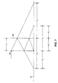
- a paraxial approximation for concave surfaces is described by Gerchman and Hunter in SPIE Vol. 192 Interferometry p. 75-84 (1979) and results from applying a Gaussian image equation and a conjugate recursion formula.
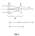
- the measurement and test objects are shown as having planar surfaces.
- an equation relating S i and T i reduces to an equation relating the radius of the mirror R to the gap L and the focal length of the lens F .
- the system is symmetrical about the optical axis.
- numerical simulations such as ray tracing programs, can be used to calculate the radius of curvature. For instance, starting with a ray at the edge of the reference element, subsequent intersections of the ray with the test object and reference element can be calculated depending on the values assigned to the gap (L) between the reference element and the test object and the radius of curvature of the test object (R). By inverting this problem and using iterative function optimizing routines, the CPU determines the value of R that best fits a particular measured gap L.
- CPU determines a value for the radius of curvature, it corrects this value to account for errors resulting from the operator's positioning of the test object at a cavity null position.
- the operator uses the visual output from camera 46 to determine when the test object is approximately in a null position.
- the operator cannot translate the test object to an exact null position and, as a result, positioning of the test object slightly behind or in front of the true null position causes fractional errors in the measured OPD and thereby produces an error in the computed radius on the order of about 0.03%.
- the positioning errors also produce focusing or imagining errors through the interferometer monitor which, in turn, result in an approximately quadratic phase deviation in the phase map of the test surface.
- Selberg discusses positioning and imaging errors in radius interferometry in Opt. Eng. 31 , 1961-6 (1992).
- apparatus 100 uses camera 46 to record a 2-dimensional intensity history of the interfering wavefronts as CPU translates mount 38.
- the CPU compares the measured phase map to a theoretical phase map.
- the CPU generates the theoretical phase map using ray tracing routines, the measured OPD, known null order and focal length of the reference element (if applicable), and the calculated radius of curvature.
- the CPU iteratively changes the value of the measured OPD, calculates a new theoretical phase map, and compares that new map to the measured phase map.
- the CPU can compare the theoretical and measured phase maps by monitoring the difference in phase between the two maps as a function of 2-dimension position. The CPU repeats this procedure until it minimizes the difference between the measured and theoretical phase maps.
- the adjusted OPD value corresponds to an OPD value which would have been measured by apparatus 100 if the test object were positioned to within about 1 micron of the exact cavity null position.
- CPU uses the null order and the adjusted OPD value, i.e., the value that produced the minimum difference between the measured and theoretical phase maps, to recalculate the radius of curvature.
- Apparatus 100 can also compare measured and theoretical 2-dimensional phase maps to correct errors in tip and tilt, as well as translation, of the test object.
- apparatus 100 can be used in an assembly line to monitor the quality of optical components each manufactured to have the same radius of curvature.
- CPU 50 of apparatus 100 can be programmed to translate mechanically successive optical components from an assembly line onto the preposition mount 47 and measure the radius of curvature of each element.
- Null fringe visibility, or contrast is important when the operator initially positions the test object in any retroreflecting or confocal position.
- the reflectivity of coating 34' on reference element 34 is selected such that null fringes are visible on monitor 49 over a large range of null positions by balancing the contrasts found in high and low order nulls.
- Ir the reference intensity and It is the test intensity.
- Apparatus 100 measures three parameters, i.e., the null order, the wavelength shift and the cavity OPD.
- the null order is an integer and therefore is assumed to be determined by the CPU without any uncertainty.
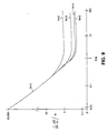
- the fractional error in the radius, ⁇ R / R expressed as a percent of the true radius can be determined by the CPU and is useful in assessing the performance of apparatus 100.
- ⁇ R / R should decrease as R increases since ⁇ R ⁇ ⁇ D is essentially constant.
- the CPU calculates the fractional uncertainty in the radius by multiplying the sensitivity and a ratio ⁇ D/R.
- F / R >1 the fractional uncertainty decreases (increases) as R increases (decreases) because the sensitivity is essentially constant.
- F/R ⁇ 1 the fractional uncertainty increases as R increases because for fixed F , the sensitivity increases more rapidly than R .
- Errors due to high order optical aberrations and imperfections in the optical components of apparatus 100 are expected to be smaller than the errors discussed above, but can be determined numerically. Departures from pure sphericity in the mirror surface also can be determined by the apparatus via an analysis of the intensity data detected by camera 46.
- the wavelength monitor OPD stability effects the accuracy at which apparatus 100 calculates the interferometer OPD.
- longer wavelength monitor OPDs provide a more accurate measure of the wavelength shift but are more difficult to keep stable.
- a typical wavelength monitor has an OPD of at least about 250mm, is stable to better than 1 part in 10 6 over an expected operating temperature range, and is insensitive to moderate acoustical and seismic influences.
- a fiber interferometer 200 includes a long length of optical fiber 202 spiraled and embedded into a thermo-electrically cooled base 204. Two couplers 206 and 208 separate and then recombine the fibers to produce long and short optical paths.
- the OPD of interferometer 200 is large, e.g., about 1m.
- Interferometer 200 is housed in a small package (approx 50mm X 50mm X 10mm).
- the thermal expansion coefficient of quartz, the material of optical fiber 202 and couplers 206 and 208, is less than 10 -6 and the index temperature sensitivity is about 10 -5 .
- the cavity length can be stabilized to about 10 -7 .
- the detectors used in both the wavelength shift monitor and test cavity monitor are standard silicon devices.
- the maximum fringe frequency is only 333KHz.
- the detector bandwidth must be at least 3 times this frequency, e.g., 1MHz, or higher. At a 1MHz sample rate, less than 20K samples of 16bit data are acquired by each detector and sent to the CPU during the sweep.
- Both the wavelength monitor and the Fizeau interferometer detectors are sampled simultaneously thereby eliminating any requirements regarding how linearly the CPU shifts the center wavelength of the light beam.
- the CPU determines the phase evolution in each cavity, i.e., wavelength monitor and Fizeau interferometer, from these data using a phase extraction algorithm such as the sliding window FFT method.
- a cavity geometry 300 for measuring concave surfaces with small radii includes a concave reference element 330 and a test object 350 having a concave surface 355.
- Concave surface 355 is positioned relative to element 330 such that the distance, M, from the object's surface to focal point, P, of element 330 is equal to radius of object 350.
- Cavity geometry 300 produces a single null fringe on the CCD camera (not shown). The size of this fringe depends only on the relative numerical apertures (NA) of the reference element and the test object.
- NA numerical apertures
- a single large null fringe representing a wavefront produced from the entire surface of the test object is observed on the visual output of camera 46 provided that the NA of the reference element is larger than the NA of the test object.
- the system operator translates test object 350 until a single large fringe appears which indicates that object 350 is positioned relative to element 330 to create cavity geometry 300.
- a cavity geometry 400 for measuring convex radii less than 100mm has a null order of 1.
- Cavity geometry 400 includes a concave reference element 430 having a focus and a test object 450 having a convex surface 455 and a back surface 460. The operator positions back surface 460 at the focal point, P, of element 430.
- apparatus 100 determines the radius of curvature as described above, except that the CPU does not need to determine the null order of the cavity.
- the CPU translates mount 38, records intensity histories on the camera, calculates a measured phase map of the test object's surface, and stores the map in memory.
- Apparatus 100 measures the OPD by shifting the center wavelength of the light beam while simultaneously monitoring the change in phase in the wavelength monitor and Fizeau interferometer monitor.
- the CPU uses these values to calculate a measured OPD and uses this value with the known focal length of the reference element to determine the radius of curvature of the test object.
- the CPU also corrects positioning errors by comparing a measured phase map to a theoretical map produced from the known focal length and measured OPD.
- the measured OPD (L) will be equal to 2(F+R) (2(F-R)) for concave (convex) mirrors when correctly nulled.
- the radii are given by (L-2F)/2 and ((2F-L)/2). The procedure for correcting the positioning errors presupposes that F is accurately known.
- the focal length of a reference element is not constant but changes with temperature. Apparatus 100 provides a convenient solution to this problem by calibrating the reference element focal length.
- a system operator positions a curved surface 605 of a test object 610 at the focal point, P, of reference object 620, i.e., at the cats-eye position.
- the CPU shifts the center wavelength of the light beam and simultaneously records intensity data from the wavelength monitor and Fizeau interferometer monitor. Using this data, the CPU determines the OPD and calculates the focal length of the reference object.
- the CPU can also correct deviations from the perfect cats-eye position and the focal length by iteratively comparing the measured phase map at the cats-eye position with a theoretical phase map created with the known focal length and measured OPD.
- the radius fractional uncertainty, ⁇ R/R depends linearly on the ratio F/R for both convex and concave small radius mirrors. Thus for fixed F the fractional uncertainty increases as R decreases. Assuming an OPD fractional uncertainty of 10 -6 , and including null cavity correction and phase errors, the fractional uncertainty for convex and concave surfaces linearly tracks the OPD error as 0.0001% per unit F/R. At F/R of 1, the fractional uncertainty is 0.0001% and at F/R of 10, the fractional uncertainty is about 0.001%.
- the confocal cavities shown in Figs. 11 and 12 act as high finesse Fizeau cavities in which there are multiple retroreflections which propagate into the interferometer monitor.
- the presence of multiple beam interference creates integer multiples of the fundamental frequency at which the intensity oscillates on the wavelength shift monitor and the cavity detector.
- Fig. 14A shows the expected intensity variation for an aluminum mirror (80% reflectivity) and a reference surface made with a 70% reflective dielectric coating resulting from multiple beam interference.
- Fig. 14B shows the intensity variation for the retroreflecting cavity of Fig. 2 which does not suffer from multiple beam interference.
- the presence of multiple beam interference is not a serious problem when determining the OPD.
- the quantity, quality and density of the intensity data recorded by the cavity detectors is high enough so that the band-limiting characteristics of the phase shifting algorithms used for extracting the phase in the OPD measurement easily track the fundamental frequency by reducing the sensitivity of the algorithm to higher-order frequencies caused by the multiple beam interference.
- any phase error is cyclic and averages out over the multiple cycles recorded for the OPD measurement.
- the multiple beam interference also creates potential problems in the intensity data recorded by the CCD camera for computing a phase map and surface profile of the test object.
- the phase shifting algorithms cannot isolate the fundamental frequency as well as they did for the OPD measurement.
- apparatus 100 records 13 intensity frames with 45 degree phase shifts between each frame.
- This particular algorithm has band-limiting characteristics which reduce the sensitivity of the algorithm to all even and odd harmonics of the fundamental frequency up to order seven but produce almost 20 nm of Peak-to-Valley (PV) error when used to analyze the intensity history shown in Fig. 14A.
- PV Peak-to-Valley
- One method for reducing this error involves reducing the magnitude of the multiple beam interference by changing the reflectivity of the reference object. For instance, if the reference object were left uncoated (a 4% reflectivity) the phase error associated with the 13 bucket algorithm drops to less than 0.2 nm PV. Of course, a lower reference reflectivity also reduces the contrast available on the CCD camera for aligning the test object and recording intensity data for phase mapping and surface profiling. The change in the contrast from a 4%-80% cavity to a 70%-80% cavity decreases by about a factor of 7, but still provides over 500 gray levels on a 12 bit CCD camera for the aligning and recording intensity data.
- apparatus 100 can shift the center wavelength of the light beam rather than translating the reference object to acquire intensity histories on the CCD camera. Shifting the wavelength generates a longer phase excursion, i.e., produces many more oscillations in the intensity history, than mechanically moving the reference object. Due to the increase in phase excursion, the CPU is able to record an increased number and density of intensity samples which, in turn, reduces the sensitivity of the phase shifting algorithms to non-fundamental frequencies.
- the CPU processes the intensity data by using a phase shifting algorithm, such as a windowed FFT, on each pixel's intensity history. For instance, apparatus 100 shifts the wavelength and the CCD camera records 64 consecutive frames at 22.5 degree phase increments. The acquisition would take only 1 ⁇ 2 second for a 120Hz camera, and the distortion induced phase error for a 70%-80% cavity would be less than 1 nm PV, i.e., improvement by a factor of 20.
- the relative change in the characteristic wavelength emitted from the light source can be determined by monitoring electronic signals from the light source.
- the light source can be calibrated so that a specific change in a driver current corresponds to a known change in optical frequency output. Monitoring the relative change in driver current could, in turn, be used to determine the relative change in the optical frequency of the characteristic wavelength.
- the percent fractional error obtained from simulating measurements on concave and convex mirrors having radii ranging from 100mm to 150m are listed in Tables 2 and 3.
- the wavelength shift detector was assumed to have 14 effective bits and cavity detector was assumed to have 12 effective bits.
- the contribution to the fractional error in D from both phase measurements is less than 0.00002%.
- the fractional uncertainty in the optical length of the wavelength shift monitor was assumed to be 10 -6 (0.0001%) making it the dominant source in the fractional error in D.
- the results are displayed assuming null cavity error correction. Null cavity gap errors are assumed to be 1 micron after correction.
- the wavelength monitor was described as a Michelson interferometer, other types of interferometers could be used, e.g. a fiber or bulk optic interferometer or a Mach-Zehnder interferometer. It should also be clear that the wavelength monitor only need s to be used if the wavelength uncertainty when scanning is too large.
- the different configurations i.e., cats-eye and confocal configurations
- the confocal configuration tends to result in higher sensitivity and/or greater accuracy
- the cats-eye configuration tends to be appropriate for long radius measurements in which one needs to limit the size of the space required for making the measurement.
Landscapes
- Physics & Mathematics (AREA)
- General Physics & Mathematics (AREA)
- Instruments For Measurement Of Length By Optical Means (AREA)
- Length Measuring Devices By Optical Means (AREA)
Applications Claiming Priority (2)
| Application Number | Priority Date | Filing Date | Title |
|---|---|---|---|
| US25211600P | 2000-11-20 | 2000-11-20 | |
| US252116P | 2000-11-20 |
Publications (2)
| Publication Number | Publication Date |
|---|---|
| EP1209442A2 true EP1209442A2 (fr) | 2002-05-29 |
| EP1209442A3 EP1209442A3 (fr) | 2003-04-09 |
Family
ID=22954675
Family Applications (1)
| Application Number | Title | Priority Date | Filing Date |
|---|---|---|---|
| EP01309759A Withdrawn EP1209442A3 (fr) | 2000-11-20 | 2001-11-20 | Mesure automatique de la rayon de courbure |
Country Status (2)
| Country | Link |
|---|---|
| US (1) | US6894788B2 (fr) |
| EP (1) | EP1209442A3 (fr) |
Cited By (6)
| Publication number | Priority date | Publication date | Assignee | Title |
|---|---|---|---|---|
| RU2215987C2 (ru) * | 2001-06-20 | 2003-11-10 | Открытое акционерное общество "ЛОМО" | Устройство для измерения радиуса сферических полированных поверхностей |
| EP1552243A4 (fr) * | 2002-06-24 | 2008-08-20 | Lightgage Inc | Interferometre a balayage de frequences et a trajectoire commune |
| CN102168955A (zh) * | 2011-05-18 | 2011-08-31 | 中国科学院长春光学精密机械与物理研究所 | 一种光学球面曲率半径的检测方法 |
| CN105115444A (zh) * | 2015-09-08 | 2015-12-02 | 上海现代先进超精密制造中心有限公司 | 一种离轴抛物面镜面形精度的检测装置及检测方法 |
| CN105571481A (zh) * | 2015-12-21 | 2016-05-11 | 中国科学院长春光学精密机械与物理研究所 | 一种高精度曲率半径测试装置及方法 |
| CN115930805A (zh) * | 2022-12-14 | 2023-04-07 | 上海电机学院 | 一种透镜中心厚度的自动测量装置与检测方法 |
Families Citing this family (18)
| Publication number | Priority date | Publication date | Assignee | Title |
|---|---|---|---|---|
| WO2003054474A1 (fr) * | 2001-12-10 | 2003-07-03 | Zygo Corporation | Procede et appareil d'etalonnage d'un interferometre accordable en longueur d'onde |
| US7259860B2 (en) * | 2004-09-22 | 2007-08-21 | Corning Incorporated | Optical feedback from mode-selective tuner |
| WO2006041447A1 (fr) * | 2004-09-25 | 2006-04-20 | Josh Hogan | Systeme d'analyse compact non invasif |
| FR2879736B1 (fr) * | 2004-12-20 | 2007-02-02 | Essilor Int | Procede et dispositif de mesure sans contact de la courbure d'un objet ophtalmique |
| US20070121115A1 (en) * | 2005-11-15 | 2007-05-31 | Zetetic Institute | Apparatus and method for reducing effects of coherent artifacts and compensation of effects of vibrations and environmental changes in interferometry |
| US8743373B1 (en) | 2006-01-13 | 2014-06-03 | Applied Science Innovations, Inc. | Metrology of optics with high aberrations |
| US7545511B1 (en) | 2006-01-13 | 2009-06-09 | Applied Science Innovations, Inc. | Transmitted wavefront metrology of optics with high aberrations |
| US8018602B1 (en) | 2006-01-13 | 2011-09-13 | Applied Science Innovations, Inc. | Metrology of optics with high aberrations |
| FR2913493B1 (fr) * | 2007-03-08 | 2009-04-17 | Essilor Int | Procede d'analyse pour la mesure sans contact des courbures locales d'un objet ophtalmique |
| JP5553593B2 (ja) * | 2009-12-16 | 2014-07-16 | キヤノン株式会社 | 面形状測定装置、面形状測定方法および光学素子の製造方法 |
| JP5618727B2 (ja) * | 2010-09-21 | 2014-11-05 | キヤノン株式会社 | 形状測定法及び形状計測装置 |
| WO2016067268A1 (fr) | 2014-10-30 | 2016-05-06 | Swat Arkadiusz | Procédé, système et sous-système servant à déterminer par interférométrie un rayon de courbure |
| CN106482839B (zh) * | 2015-08-24 | 2019-06-21 | 南京理工大学 | 斐索式双波长干涉测试装置及其合成波长相位提取方法 |
| US9857169B1 (en) * | 2015-12-21 | 2018-01-02 | 4D Technology Corporation | Single-step interferometric radius-of-curvature measurements utilizing short-coherence sources |
| US10816408B1 (en) * | 2017-04-24 | 2020-10-27 | Apre Instruments, Llc. | Wavelength shifting in spectrally-controlled interferometry |
| US11221211B2 (en) | 2018-01-26 | 2022-01-11 | Vanderbilt University | Systems and methods for non-destructive evaluation of optical material properties and surfaces |
| DE102018111466B4 (de) * | 2018-05-14 | 2024-07-25 | Carl Mahr Holding Gmbh | Verfahren zur justage einer messvorrichtung mittels eines justagekörpers, justagekörper und verfahren zur justage eines justagekörpers |
| US11493751B2 (en) | 2019-01-23 | 2022-11-08 | Vanderbilt University | Systems and methods for compact optical relay |
Family Cites Families (11)
| Publication number | Priority date | Publication date | Assignee | Title |
|---|---|---|---|---|
| US4572628A (en) | 1981-05-29 | 1986-02-25 | Nippon Kogaku K.K. | Method of and apparatus for measuring radius |
| US4594003A (en) | 1983-07-20 | 1986-06-10 | Zygo Corporation | Interferometric wavefront measurement |
| JPS61280543A (ja) | 1985-06-05 | 1986-12-11 | San Haitetsuku Kk | 光学系の屈折力の測定装置 |
| JPH0812127B2 (ja) | 1988-11-11 | 1996-02-07 | オリンパス光学工業株式会社 | 曲率半径測定装置及び方法 |
| US5090811A (en) | 1989-05-31 | 1992-02-25 | General Electric Company | Optical radius gauge |
| US5280336A (en) | 1991-03-29 | 1994-01-18 | Optikos Corporation | Automated radius measurement apparatus |
| US5473434A (en) * | 1994-05-16 | 1995-12-05 | Zygo Corporation | Phase shifting interferometer and method for surface topography measurement |
| JPH09138181A (ja) | 1995-11-15 | 1997-05-27 | Nikon Corp | 光学系の屈折力および曲率半径の測定装置 |
| US5706086A (en) * | 1996-02-28 | 1998-01-06 | Hughes Aircraft Company | System for measuring surface aberrations of concave cylindrical surfaces |
| US5907404A (en) * | 1997-09-08 | 1999-05-25 | Erim International, Inc. | Multiple wavelength image plane interferometry |
| US5880841A (en) * | 1997-09-08 | 1999-03-09 | Erim International, Inc. | Method and apparatus for three-dimensional imaging using laser illumination interferometry |
-
2001
- 2001-11-19 US US09/988,891 patent/US6894788B2/en not_active Expired - Lifetime
- 2001-11-20 EP EP01309759A patent/EP1209442A3/fr not_active Withdrawn
Cited By (8)
| Publication number | Priority date | Publication date | Assignee | Title |
|---|---|---|---|---|
| RU2215987C2 (ru) * | 2001-06-20 | 2003-11-10 | Открытое акционерное общество "ЛОМО" | Устройство для измерения радиуса сферических полированных поверхностей |
| EP1552243A4 (fr) * | 2002-06-24 | 2008-08-20 | Lightgage Inc | Interferometre a balayage de frequences et a trajectoire commune |
| CN102168955A (zh) * | 2011-05-18 | 2011-08-31 | 中国科学院长春光学精密机械与物理研究所 | 一种光学球面曲率半径的检测方法 |
| CN102168955B (zh) * | 2011-05-18 | 2012-09-19 | 中国科学院长春光学精密机械与物理研究所 | 一种光学球面曲率半径的检测方法 |
| CN105115444A (zh) * | 2015-09-08 | 2015-12-02 | 上海现代先进超精密制造中心有限公司 | 一种离轴抛物面镜面形精度的检测装置及检测方法 |
| CN105115444B (zh) * | 2015-09-08 | 2018-09-07 | 上海现代先进超精密制造中心有限公司 | 一种离轴抛物面镜面形精度的检测装置及检测方法 |
| CN105571481A (zh) * | 2015-12-21 | 2016-05-11 | 中国科学院长春光学精密机械与物理研究所 | 一种高精度曲率半径测试装置及方法 |
| CN115930805A (zh) * | 2022-12-14 | 2023-04-07 | 上海电机学院 | 一种透镜中心厚度的自动测量装置与检测方法 |
Also Published As
| Publication number | Publication date |
|---|---|
| EP1209442A3 (fr) | 2003-04-09 |
| US6894788B2 (en) | 2005-05-17 |
| US20020126293A1 (en) | 2002-09-12 |
Similar Documents
| Publication | Publication Date | Title |
|---|---|---|
| US6894788B2 (en) | Interferometric system for automated radius of curvature measurements | |
| JP4312602B2 (ja) | 非球面表面および波面の走査干渉計 | |
| US6781700B2 (en) | Scanning interferometer for aspheric surfaces and wavefronts | |
| JP4250530B2 (ja) | 位相シフト干渉分析の方法及びシステム | |
| US5004346A (en) | Method of examining an optical component | |
| US7218403B2 (en) | Scanning interferometer for aspheric surfaces and wavefronts | |
| US6771375B2 (en) | Apparatus and method for measuring aspherical optical surfaces and wavefronts | |
| US6714308B2 (en) | Rapid in-situ mastering of an aspheric fizeau | |
| US6972849B2 (en) | Scanning interferometer for aspheric surfaces and wavefronts | |
| EP1869401B1 (fr) | Procede permettant d'effectuer des mesures de haute resolution precises de surfaces aspheriques | |
| JPH09503065A (ja) | 表面形状を測定する干渉計測方法及び装置 | |
| EP2306144A1 (fr) | Appareil de mesure de la forme de surface | |
| US20150077759A1 (en) | Compact, Slope Sensitive Optical Probe | |
| US6734979B2 (en) | Rapid in situ mastering of an aspheric Fizeau with residual error compensation | |
| US20030025915A1 (en) | Method for absolute calibration of an interferometer | |
| US6801323B2 (en) | Methods and apparatus for interferometric dimensional metrology | |
| US7042578B2 (en) | Method and apparatus for absolute figure metrology | |
| Disawal et al. | Simultaneous measurement of thickness and refractive index using phase shifted Coherent Gradient Sensor | |
| JP2831428B2 (ja) | 非球面形状測定機 | |
| Weingaertner et al. | Simultaneous distance, slope, curvature, and shape measurement with a multipurpose interferometer | |
| JP2000275021A (ja) | 面形状測定装置 | |
| JPH10260020A (ja) | 非球面形状測定装置及び方法 | |
| JPH10213421A (ja) | ヌル波面計測装置 | |
| JP2000275005A (ja) | 波面形状測定方法 | |
| JPH10221031A (ja) | 非球面形状測定装置 |
Legal Events
| Date | Code | Title | Description |
|---|---|---|---|
| PUAI | Public reference made under article 153(3) epc to a published international application that has entered the european phase |
Free format text: ORIGINAL CODE: 0009012 |
|
| 17P | Request for examination filed |
Effective date: 20011203 |
|
| AK | Designated contracting states |
Kind code of ref document: A2 Designated state(s): AT BE CH CY DE DK ES FI FR GB GR IE IT LI LU MC NL PT SE TR |
|
| AX | Request for extension of the european patent |
Free format text: AL;LT;LV;MK;RO;SI |
|
| PUAL | Search report despatched |
Free format text: ORIGINAL CODE: 0009013 |
|
| AK | Designated contracting states |
Kind code of ref document: A3 Designated state(s): AT BE CH CY DE DK ES FI FR GB GR IE IT LI LU MC NL PT SE TR Designated state(s): AT BE CH CY DE DK ES FI FR GB GR IE IT LI LU MC NL PT SE TR |
|
| AX | Request for extension of the european patent |
Extension state: AL LT LV MK RO SI |
|
| RIC1 | Information provided on ipc code assigned before grant |
Ipc: 7G 01B 9/02 B Ipc: 7G 01B 11/24 A |
|
| AKX | Designation fees paid |
Designated state(s): DE NL |
|
| STAA | Information on the status of an ep patent application or granted ep patent |
Free format text: STATUS: THE APPLICATION IS DEEMED TO BE WITHDRAWN |
|
| 18D | Application deemed to be withdrawn |
Effective date: 20070531 |