EP1209490A2 - Lentille d'objectif pour disque optique - Google Patents
Lentille d'objectif pour disque optique Download PDFInfo
- Publication number
- EP1209490A2 EP1209490A2 EP01126496A EP01126496A EP1209490A2 EP 1209490 A2 EP1209490 A2 EP 1209490A2 EP 01126496 A EP01126496 A EP 01126496A EP 01126496 A EP01126496 A EP 01126496A EP 1209490 A2 EP1209490 A2 EP 1209490A2
- Authority
- EP
- European Patent Office
- Prior art keywords
- lens
- aberration
- objective lens
- optical disk
- denotes
- Prior art date
- Legal status (The legal status is an assumption and is not a legal conclusion. Google has not performed a legal analysis and makes no representation as to the accuracy of the status listed.)
- Withdrawn
Links
Images






Classifications
-
- G—PHYSICS
- G02—OPTICS
- G02B—OPTICAL ELEMENTS, SYSTEMS OR APPARATUS
- G02B15/00—Optical objectives with means for varying the magnification
- G02B15/14—Optical objectives with means for varying the magnification by axial movement of one or more lenses or groups of lenses relative to the image plane for continuously varying the equivalent focal length of the objective
- G02B15/22—Optical objectives with means for varying the magnification by axial movement of one or more lenses or groups of lenses relative to the image plane for continuously varying the equivalent focal length of the objective with movable lens means specially adapted for focusing at close distances
-
- G—PHYSICS
- G11—INFORMATION STORAGE
- G11B—INFORMATION STORAGE BASED ON RELATIVE MOVEMENT BETWEEN RECORD CARRIER AND TRANSDUCER
- G11B7/00—Recording or reproducing by optical means, e.g. recording using a thermal beam of optical radiation by modifying optical properties or the physical structure, reproducing using an optical beam at lower power by sensing optical properties; Record carriers therefor
- G11B7/12—Heads, e.g. forming of the optical beam spot or modulation of the optical beam
- G11B7/135—Means for guiding the beam from the source to the record carrier or from the record carrier to the detector
- G11B7/1372—Lenses
- G11B7/1374—Objective lenses
-
- G—PHYSICS
- G11—INFORMATION STORAGE
- G11B—INFORMATION STORAGE BASED ON RELATIVE MOVEMENT BETWEEN RECORD CARRIER AND TRANSDUCER
- G11B7/00—Recording or reproducing by optical means, e.g. recording using a thermal beam of optical radiation by modifying optical properties or the physical structure, reproducing using an optical beam at lower power by sensing optical properties; Record carriers therefor
- G11B7/12—Heads, e.g. forming of the optical beam spot or modulation of the optical beam
- G11B7/135—Means for guiding the beam from the source to the record carrier or from the record carrier to the detector
- G11B7/1392—Means for controlling the beam wavefront, e.g. for correction of aberration
- G11B7/13922—Means for controlling the beam wavefront, e.g. for correction of aberration passive
Definitions
- the present invention relates to an objective lens having a high numerical aperture (NA) which realizes a large-capacity optical disk.
- NA numerical aperture
- an objective lens whose numerical aperture is in a range of 0.45 to 0.5 is used, and reading or writing is performed with a laser beam having a wavelength of about 780 nm.
- the objective lens having a numerical aperture of about 0.6 is used, and reading or writing is performed with the laser beam which has a wavelength of about 650 nm.
- next-generation optical disk pickup system in which the laser beam having a shorter wavelength and the lens having a higher numerical aperture are used has been developed in order to enhance a capacity of the optical disk.
- so-called blue laser having a wavelength of 400 nm is considered as the laser which has the shorter wavelength.
- an optical pickup having a simpler constitution by the single lens has been desired as the next-generation system.
- an objective lens for the optical disk having a numerical aperture larger than 0.7, has been desired in the optical pickup in which the single lens is used.
- problems for bringing the single lens having a high or large numerical aperture into practical use are that (1) a manufacturing tolerance becomes strict and (2) designed properties are deteriorated.
- the manufacturing tolerance means an interval tolerance between incidence and emission surfaces in a bi-asymmetrical lens (a lens with two asymmetrical surfaces), an interval tolerance (eccentricity tolerance) between geometric centers of the incidence and emission surfaces, a tolerance of inclination between the incidence and emission surfaces, or the like.
- the eccentricity tolerance is determined based on an increase amount of wavefront aberration when there is eccentricity.
- the manufacturing tolerance can be realized by improvement and enhancement of a manufacturing technique. That is, it is possible to manufacture the lens in which the tolerance is secured in a range of several micrometers to several tens of micrometers.
- the deterioration of designed properties indicates deterioration of properties in lens design.
- the deterioration means generation of an aberration with respect to an out-of-axis light beam (hereinafter referred to as the out-of-axis aberration) and a spherical aberration in a best image surface in each wavelength with respect to an axial light beam having a plurality of wavelengths (hereinafter referred to as a best image surface chromatic aberration).
- the axial light beam means a light beam which is incident in parallel to the optical axis of the lens
- the out-of-axis light beam means a light beam which is incident in an inclined manner with respect to the optical axis of the lens.
- the out-of-axis aberration is generally inferior to the conventional aberration. This is because with a larger numerical aperture a light beam having a large inclination angle with respect to the optical axis is incident.
- the eccentricity tolerance A most important tolerance among the manufacturing tolerances is the eccentricity tolerance. That is, with a molded lens, the eccentricity between lens surfaces is determined by attachment precision of upper and lower molds, looseness during attachment (the mold moves during molding, and the looseness includes an allowance of sliding during molding, and an allowance of contraction by temperature change during molding), and the like. An inclination between the surfaces is sometimes generated with the eccentricity. However, the inclination and eccentricity have considerably close influence on the aberration, and an amount to be handled is of a ⁇ m order and is considerably small. Therefore, the inclination and eccentricity are usually collectively treated as the eccentricity.
- the tolerance indicates an essential value for manufacturing.
- the conventional lens for the DVD having a low NA, even when there is eccentricity of about 10 ⁇ m in the design, it is possible to design and suppress the increase of the aberration to 0.02 ⁇ or less. Moreover, a process for suppressing the eccentricity to 10 ⁇ m is established. Furthermore, it is also possible to obtain a precision, for example, of about 5 ⁇ m or less by a recent improvement of the process. However, when the allowance of sliding, or the like is considered, it is considerably difficult to set the precision to 1 to 2 ⁇ m or less.
- the lens design it is necessary to secure a certain degree of eccentricity tolerance in the lens design.
- the axial aberration is only slightly deteriorated.
- the eccentricity tolerance of micron order which can realize manufacturing cannot be secured without considerably sacrificing the out-of-axis aberration.
- the lens for the DVD having a focal distance of 3.3 mm and a thickness of 2 mm, for example, when the lens having an eccentricity tolerance of 5 ⁇ m is designed, the lens having the out-of-axis aberration of 0.03 ⁇ or less with respect to an incident light of 0.5 degree can easily be manufactured.
- the best image surface chromatic aberration is a spherical aberration generated when the wavelength of the laser beam deviates from the designed wavelength of the lens and is evaluated on the best image surface with respect to the laser wavelength. This will be described hereinafter in further detail.
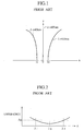
- FIG.1 is a diagram showing a longitudinal aberration generated with respect to lights of 400 nm and 410 nm, when the aberration is compensated for with respect to the light of 405 nm.
- a curved line indicating the longitudinal aberration means that there is a spherical aberration.
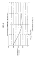
- FIG.2 shows a relation between the best image surface chromatic aberration and the wavelength when the aberration is evaluated as an amount of wavefront aberration (the relation will hereinafter be referred to as a best image surface chromatic aberration characteristic).
- the best image surface chromatic aberration characteristic has a minimum value in a design reference wavelength ⁇ 0 of the lens, and has a larger value with deviation from the design reference wavelength. Therefore, a wavelength range ⁇ (maximum wavelength ⁇ +, minimum wavelength ⁇ -) in which the lens can be used is determined from the best image surface chromatic aberration characteristic of FIG.2.
- a wavelength in which the best image surface chromatic aberration can be suppressed to 0.02 ⁇ or less with generation of a wavelength change ranges from 615 nm to 700 nm, and indicates a very broad range.
- the best image surface chromatic aberration characteristic becomes strict in a wavelength range of blue laser, and it is difficult to obtain a broad wavelength range.
- the focal distance of the objective lens is desired to be set, for example, to 2.2 mm or less.
- a first object of the present invention is to solve the aforementioned problem, and to provide an objective lens for an optical disk, which is superior in a best image surface chromatic aberration characteristic and out-of-axis aberration characteristic and which has a moderate eccentricity tolerance.
- a second object of the present invention is to solve the aforementioned problem, and to provide an objective lens for an optical disk, which is constituted of a single lens having a numerical aperture of 0.7 to 0.8, which can be used in the optical disk having a 0.3 mm or thinner reproducing transmission layer, and which has the following characteristics (1) to (4) with respect to a light having a wavelength of about 400 nm.
- an objective lens for an optical disk comprising a bi-aspherical single lens having a numerical aperture of 0.7 or more, wherein a center thickness of the lens is more than a focal distance.
- a declination during refraction in a first surface of the lens can be reduced.
- a curvature radius of the first surface can be reduced and an angle formed by a normal of the first surface and an optical axis can be reduced. Therefore, a change of a refraction angle with a change of a wavelength can be minimized and generation of a spherical aberration can be inhibited. That is, a chromatic aberration in a best image surface can be improved.
- a change of a direction of an incident light has a reduced influence on a change of the refraction angle after emission from the first surface, and the out-of-axis aberration can be minimized.
- an image forming magnification in a design reference wavelength is 0 times.
- the design reference wavelength is a wavelength employed as a reference in designing the lens, and the lens allows the light having the design reference wavelength, including an out-of-axis light beam and axial light beam, to most sharply converge on the same image surface.
- an interferometer can be used to easily measure the properties singly with the lens, and a high-degree quality control can be achieved.
- the design reference wavelength is shorter than 0.45 ⁇ m.
- d denotes a thickness of the optical disk
- n denotes a refractive index of the optical disk
- an operation distance (distance between a tip end of the lens and the surface of the disk) of 0.3 mm or more can be secured.
- an operation distance of 0.25 mm or more is secured, a possibility of collision of the lens with the disk can be reduced. That is, a disk formed of plastic has a warpage. An amount of warpage also depends on a diameter of the disk. For example, a side-runout of the disk for the next-generation system, having a size of 120 mm, is considered to be about ⁇ 0.2 mm.
- a danger of collision of the disk with the lens can be reduced to a necessary and sufficient degree.
- a lens having a shorter focal distance can also be used.
- the focal distance when the focal distance is designed to 4.0 mm or less, a diameter of a light flux can be set to 5.6 mm or less even with a numerical aperture of 0.7 or more, and miniaturization of the pickup can be assured.
- the lens can also be kept to be miniaturized and lightened, a broad range characteristic of an actuator for use in a focus servo or a tracking servo can be held, and a servo characteristic requiring a broad band can be obtained.
- an objective lens for an optical disk comprising a single lens having at least one surface formed in an aspheric shape and having a numerical aperture of 0.7 to 0.8 and an operation distance of 0.2 mm or more, and satisfying the following condition. 0.85 ⁇ d 1 /f ⁇ 1.5 0 > d 1 /R2 > -0.7 n > 1.6
- f denotes a focal distance of the lens
- d 1 denotes a center thickness of the lens
- R2 denotes a curvature radius in a vertex of the lens on an optical disk side
- n denotes a refractive index of the lens.
- the focal distance is 2.2 mm or less.
- a thickness of a transmission layer of the optical disk is 0.3 mm or less.
- an objective lens for an optical disk comprising a single lens having at least one surface formed in an aspheric shape and having a numerical aperture of 0.78 or more, and satisfying the following condition. d 1 /f > 1.2 0.65 ⁇ R1/f ⁇ 0.95
- f denotes a focal distance of the lens
- d 1 denotes a center thickness of the lens
- R1 denotes a curvature radius in a vertex of the lens on a light source side
- R2 denotes a curvature radius in the vertex of the lens on an optical disk side
- n denotes a refractive index of the lens.
- the operation distance is 0.3 mm or more.
- a thickness of a transmission layer of the optical disk is 0.3 mm or less.
- FIG.3 shows an optical-disk objective lens 21 according to a first embodiment of the present invention and an optical disk 23 for use together with the objective lens 21.
- the optical-disk objective lens 21 of the first embodiment is a bi-aspherical single lens (a single lens with two aspheric surfaces) generally having a design reference wavelength shorter than 450 nm, a numerical aperture of 0.7 or more, and a center thickness D of the lens more than a focal distance.
- the design reference wavelength of the objective lens 21 is set to 405 nm.
- NA numerical aperture
- the focal distance of the objective lens 21 is 2.5 mm, and an image forming magnification in the design reference wavelength of 405 nm is 0 times.
- an eccentricity ⁇ between a first surface S1 and a second surface S2 (distance between a geometric center axis a1 of the surface S1 and a geometric center axis a2 of the surface S2) is 5 ⁇ m
- an aberration (eccentricity characteristic) is designed to be 0.03 ⁇ or less.
- a glass type of the lens is as follows.
- optical disk 23 is designed as follows.
- Thickness of cover glass 0.11 mm (polycarbonate 0.1 mm + acrylic 0.01 mm).
- the objective lens 21 is designed such that aberration with respect to a light beam parallel to an axis, that is, an axial aberration has a size of about 0.003 ⁇ (rms).
- rms means a root mean square.
- ⁇ denotes a design reference wavelength, and is 405 nm in the first embodiment.
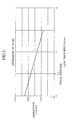
- FIG.4 shows a fluctuation of an out-of-axis aberration with a change of the center thickness D of the lens in the objective lens 21 of the first embodiment.
- the out-of-axis aberration means aberration generated on a focal surface when the light beam is incident at an inclination angle with respect to an optical axis of the lens. Additionally, it is assumed in FIG. 4 that the light beam is incident at an angle of 0.5 degree with respect to the optical axis.
- FIG.4 shows values calculated by a light beam tracking method with respect to the objective lens 21.
- the lens thickness D is larger than the focal distance (2.5 mm)
- the aberration becomes smaller than 0.04 ⁇ (rms) and a satisfactory converged image can be obtained.
- FIG.5 shows a change of the best image surface chromatic aberration with a change of the center thickness D of the lens in the objective lens 21 of the first embodiment.
- the change of a spherical aberration (rms) of the light beam having a wavelength of 410 nm deviating from a design reference wavelength of 405 nm is shown with the change of the lens thickness D.
- the spherical aberration (rms) in 410 nm also indicates a sufficiently small value (smaller than 0.02 ⁇ in FIG.5) when the center thickness D of the lens is larger than a focal distance of 2.5 mm.
- the center thickness D of the lens when the center thickness D of the lens is set to be larger than the focal distance, a satisfactory best image surface chromatic aberration characteristic and out-of-axis aberration characteristic can be obtained. Moreover, according to the lens of the first embodiment, when the center thickness D of the lens is set to be larger than the focal distance of 2.5 mm, a usable range of a laser wavelength can be broadened.
- the values of out-of-axis aberration and best image surface chromatic aberration of FIGS.4 and 5 differ with differences of designs such as the numerical aperture of the lens and a type of glass forming the lens.
- the values also differ with specifications of the lens.
- the focal distance is shortened, the characteristic regarding the aberration is enhanced as a natural result.
- the center thickness of the lens is set to be larger than the focal distance in a bi-asymmetrical single lens (a single lens with two asymmetrical surfaces) having a light wavelength shorter than 450 nm and a numerical aperture of 0.7 or more
- the objective lens for the optical disk having a satisfactory chromatic aberration characteristic and out-of-axis aberration characteristic can be made. This respect can be considered in a generalized manner.
- the design reference wavelength shorter than 0.45 ⁇ m and the numerical aperture of 0.7 or more when the center thickness D of the lens is set to be larger than the focal distance, the satisfactory best image surface chromatic aberration characteristic and out-of-axis aberration characteristic can be obtained.
- an interferometer when the image forming magnification in the design reference wavelength is set to 0 times, an interferometer can be used to easily measure the properties singly with the lens, and a high-degree quality control can be achieved.
- FIG.6 shows an optical-disk objective lens 31 according to a second embodiment of the present invention and an optical disk 33 for use together with the objective lens 31.
- Lens specifications of the optical-disk objective lens 31 of the second embodiment are shown in Table 1. Specifications on lens Designed wavelength 405 nm NA 0.75 Focal distance 2.5 mm Entrance pupil diameter 3.75 mm
- lens designed values of the objective lens 31 are shown in Table 2. Designed values of lens Surface number Surface shape Radius Thickness Glass Conic constant 1 Aspheric surface 2.075403 3.500002 NBF1 -0.2798963 2 Aspheric surface -6.962995 0.598987 -529.1943 3 Infinity 0.1 POLYCARB 4 Infinity 0.01 ACRYLIC Image surface
- third and fourth surfaces indicate the designed values of the optical disk 33.
- aspheric coefficients of first and second surfaces of the objective lens 31 are shown in Tables 4 and 5.
- Second surface Coefficient A4 of r 4 0.031198858 Coefficient A6 of r 6 -0.056548233 Coefficient A8 of r 8 0.033199766 Coefficient A10 of r 10 -0.00049162717 Coefficient A12 of r 12 -0.0038802889
- a distance X from a tangential plane of an aspheric vertex of a coordinate point on an aspheric surface having a height Y of the optical axis is represented by the following equation, assuming that a curvature (1/r) of the aspheric vertex is C, a conic coefficient (conic constant) is K, and 4-dimensional to 12-dimensional aspheric coefficients are A4 to A12.
- X CY 2 /[1 + ⁇ 1 - (1+K)C 2 Y 2 ⁇ ] + A4Y 4 + A6Y 6 + A8Y 8 + A10Y 10 + A12Y 12
- FIG.7 is a longitudinal aberration diagram in three wavelengths of 400 nm, 405 nm, 410 nm in the objective lens 31 of the second embodiment.
- the best image surface aberration (rms) of the objective lens 31 is shown in Table 6.
- the optical-disk objective lens 31 superior in the best image surface chromatic aberration characteristic can be realized.
- the objective lens 31 when a face-to-face eccentricity is 5 ⁇ m, the aberration is 0.025 ⁇ (rms). Furthermore, the operation distance is 0.60 mm in the objective lens 31.
- FIG.8 shows an optical-disk objective lens 41 according to a third embodiment of the present invention and an optical disk 43 for use together with the objective lens 41.
- the lens specifications of the optical-disk objective lens 41 of the third embodiment are shown in Table 7. Specifications on lens Designed wavelength 405 nm NA 0.75 Focal distance 1.5 mm Entrance pupil diameter 2.25 mm
- the lens designed values of the objective lens 41 are shown in Table 8. Designed values of lens Surface number Surface shape Radius Thickness Glass Conic constant 1 Aspheric surface 1.186043 1.7 NBF1 -0.2942041 2 Aspheric surface -15.83456 0.497105 -4974.452 3 Infinity 0.1 POLYCARB 4 Infinity 0.01 ACRYLIC Image surface
- the third and fourth surfaces indicate the designed values of the optical disk 43.
- FIG.9 is a longitudinal aberration diagram in three wavelengths of 400 nm, 405 nm, 410 nm in the objective lens of the third embodiment.
- the best image surface aberration (rms) of the objective lens 41 is shown in Table 11.
- the optical-disk objective lens 41 superior in the best image surface chromatic aberration characteristic can be realized.
- the objective lens 41 when the face-to-face eccentricity is 5 ⁇ m, the aberration is 0.027 ⁇ (rms). Furthermore, the operation distance is 0.50 mm in the objective lens 41.
- a fourth embodiment of the present invention has been developed based on the following consideration.
- the lens may be designed, for example, so as to correct the spherical aberration.
- the lens may be designed, for example, so as to satisfy an Abbe's sine condition.
- the bi-aspherical single lens (the single lens with two aspheric surfaces) can simultaneously satisfy these two conditions. That is, when incidence and emission surfaces are formed into an aspheric lens, the lens simultaneously satisfying the two conditions can be designed.
- an aspheric lens shape is necessary in which each aberration does not largely increase even with the incidence and emission surfaces having the eccentricity.
- the objective lens according to the aforementioned consideration is a single lens having at least one surface formed in an aspheric shape and having a numerical aperture of 0.7 to 0.8 and an operation distance of 0.2 mm or more, and is the objective lens for the optical disk, which satisfies the following conditions: (1) 0.85 ⁇ d 1 /f ⁇ 1.5; (2) 0 > d 1 /R2 > -0.7; and (3) n > 1.6.
- f denotes a focal distance of the objective lens
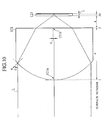
- d 1 denotes a center thickness of an objective lens 121 (see FIG.10).
- R2 denotes a curvature radius in a vertex 121b of the objective lens 121 on a side of an optical disk 123.
- R1 denotes a curvature radius in a vertex 121a of the objective lens 121 on a light source side.
- the objective lens 121 can simultaneously satisfy the axial aberration characteristic, out-of-axis aberration characteristic, and eccentricity tolerance (resulting in suppression of aberration increase).
- the axial aberration can be set to 0.01 ⁇ or less
- the out-of-axis aberration can be set to 0.05 ⁇ or less with respect to the incident light of 0.5 degree.
- the wavefront aberration can be set to 0.03 ⁇ or less with respect to the eccentricity of 5 ⁇ m. Additionally, these aberrations can further be reduced in accordance with the focal distance.
- the eccentricity tolerance can be secured while suppressing the axial and out-of-axis aberrations.
- a radius of the first surface (incidence surface) of the lens can be set to be relatively large with a larger core thickness of the lens.
- an incidence angle ⁇ angle formed by a normal n of the lens surface and the light beam
- a light beam L FOG.10
- the out-of-axis aberration characteristic can effectively be held.
- d 1 is relatively small, the operation distance can be secured even with a relatively large R2. Therefore, the sine condition can relatively easily be satisfied, and the out-of-axis aberration can also be suppressed.
- the lens can be miniaturized and lightened, and a high-speed operation by an actuator can be assured in focus servo and tracking servo operations. Additionally, miniaturization of a pickup can be assured.
- a negative value of d 1 /R2 means that R2 is negative, and this means that the objective lens 121 is a double convex lens. This can enlarge the eccentricity tolerance (refer to the following description of condition (4)).
- a power of the convex lens can thereby be shared by R1 and R2, R1 can be set to be relatively large as a result, and an operation distance a (FIG.10) can be lengthened.
- the equation represents the operation distance in air, but the distance does not essentially change even when the light is focused on the disk.
- d/R2 is set to be larger than -0.7, estrangement from a complete aplanat form is reduced, the out-of-axis aberration is therefore reduced/suppressed, and the aberrations can be balanced.
- n > 1.6 a large numerical aperture can easily be achieved in a relatively shallow spherical surface easy to be processed (spherical surface having a small angle ⁇ (FIG.10) formed by the normal direction of the lens surface and the optical axis in an outermost periphery of the lens).
- a refractive index n is more preferably 1.7 or more.
- the objective lens 121 of the fourth embodiment further preferably satisfies condition: (4) 0.65 ⁇ R1/f ⁇ 0.9.
- R1/f is set to be smaller than 0.9, the violation amount of the sine condition is suppressed, and the out-of-axis aberration can be held to be satisfactory.
- the value of curvature radius R1 of the first surface is set to be large and to form the double convex lens.
- the value of R2 can be held to be relatively small, the violation amount of the sine condition can easily be suppressed as a result, and the out-of-axis aberration can be held to be satisfactory.
- the out-of-axis aberration (wavefront aberration) can be suppressed to 0.07 ⁇ or less with respect to the incident light having an incidence angle of 0.5 degree.
- the lens of the present embodiment more preferably satisfies condition: (5)
- the spherical aberration (wavefront aberration) can be reduced/suppressed as described above.
- a combination of radii for minimizing the spherical aberration is known in the bi-aspherical single lens, and the objective lens 121 is called a best form lens.
- the estrangement from the best form lens is reduced, and the spherical aberration can be reduced.
- the spherical aberration can further easily be corrected, and a balance among the axial and out-of-axis aberrations and eccentricity tolerance can be kept to be satisfactory.
- the focal distance is preferably set to 2.2 mm or less in the objective lens 121 of the fourth embodiment.
- the optical pickup can thereby be miniaturized.
- the small-sized pickup can be used, for example, in a drive for recording data in a mobile application.
- the objective lens 121 of the fourth embodiment is preferably used together with the optical disk 121 having a 0.3 mm or thinner transmission layer.
- the specifications of the objective lens 121 are shown in Table 12. Specifications on lens Designed wavelength 405 nm NA 0.75 Focal distance 2.0 mm Entrance pupil diameter 3 mm
- the designed values of the objective lens 121 are shown in Table 13. Designed values of lens Surface number Surface shape Radius Thickness Glass (Refractive index) Conic constant 1 Aspheric surface 1.5711 2.2 NBF1 (1.76898499) -0.55559 2 Aspheric surface -28.5721 0.72 - 126.4458 3 - Infinity 0.09 POLYCARB (1.62230752) - 4 - Infinity 0.01 ACRYLIC (1.50650420) - Image surface - - - - - - - - -
- the third and fourth surfaces indicate respective surfaces of the transmission layer of the optical disk 123 (see FIG.10).
- a unit of radius or thickness is mm.
- aspheric coefficients of the first and second surfaces are shown in Tables 14, 15. Aspheric surface coefficient First surface Coefficient A4 of r 4 0.0042467 Coefficient A6 of r 6 -0.00083941 Coefficient A8 of r 8 0.0013892 Coefficient A10 of r 10 -0.00092572 Coefficient A12 of r 12 0.00013133 Aspheric surface coefficient Second surface Coefficient A4 of r 4 0.073942 Coefficient A6 of r 6 -0.14198 Coefficient A8 of r 8 0.12620 Coefficient A10 of r 10 -0.042768
- FIG.11 is a longitudinal aberration diagram of Example 4-1
- FIG.12 is an astigmatism diagram.
- the wavefront aberration on the axis is small as 0.006 ⁇ , and it can be said that there is practically no aberration. Moreover, the wavefront aberration is 0.41 ⁇ with respect to the out-of-axis incident light beam having an incidence angle of 0.5 degree with respect to the optical axis, and this similarly indicates a satisfactory characteristic. Furthermore, for the face-to-face eccentricity, when the eccentricity amount is 5 ⁇ m, the wavefront aberration is 0.016 ⁇ , and a slight increase of aberration is seen, but there is no practical problem. That is, the objective lens 121 has a manufacturing tolerance which can sufficiently bear mass production. Moreover, the operation distance is 0.72 mm, and this is a sufficiently large value.
- the specifications of the objective lens 121 are shown in Table 16. Specifications on lens Designed wavelength 405 nm NA 0.78 Focal distance 1.5 mm Entrance pupil diameter 2.34 mm
- the designed values of the objective lens 121 are shown in Table 17. Designed values of lens Surface number Surface shape Radius Thickness Glass (Refractive index) Conic constant 1 Aspheric surface 1.1879 1.70 NBF1 (1.76898499) -0.61429 2 Aspheric surface -15.0620 0.5 - -14462.3 3 - Infinity 0.09 POLYCARB (1.62230752) - 4 - Infinity 0.01 ACRYLIC (1.50650420) - Image surface - - - - - - - - - -
- the third and fourth surfaces indicate the respective surfaces of the transmission layer of the optical disk 123 (see FIG.10).
- the unit of radius or thickness is mm.
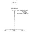
- FIG. 13 is a longitudinal aberration diagram of Example 4-2, and FIG.14 is an astigmatism diagram.
- the axial wavefront aberration is 0.003 ⁇ , and it can be said that there is substantially no aberration.
- the out-of-axis wavefront aberration is 0.045 ⁇ with respect to the out-of-axis incident light beam having the incidence angle of 0.5 degree, and this indicates a practically satisfactory characteristic.
- this objective lens also has a manufacturing tolerance which can bear mass production. Moreover, the operation distance of the objective lens 121 is 0.5 mm, and the lens has a practically sufficient broad value.
- a fifth embodiment of the present invention has been developed based on the following consideration.
- the lens may be designed, for example, so as to correct the spherical aberration.
- the lens may be designed, for example, so as to satisfy the Abbe's sine condition.
- the bi-aspherical single lens (the single lens with two aspheric surfaces) can simultaneously satisfy these two conditions. That is, when the incidence and emission surfaces are formed into the aspheric lens, the lens simultaneously satisfying the two conditions can be designed.
- the aspheric lens shape is necessary in which each aberration does not largely increase even with the incidence and emission surfaces having the eccentricity.
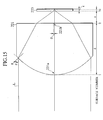
- the objective lens according to the aforementioned consideration is a single lens having at least one of a light source side surface and optical disk side surface formed in an aspheric shape and having a numerical aperture of 0.78 or more, and the lens satisfies the following conditions: (1) d 1 /f > 1.2; (2) 0.65 ⁇ R1/f ⁇ 0.95; (3)
- f denotes the focal distance of the objective lens
- d 1 denotes the center thickness of an objective lens 221 (FIG.15).
- R1 denotes a curvature radius in a vertex 221a of the objective lens 221 on the light source side
- R2 denotes a curvature radius in a vertex 221b of the objective lens 221 on the side of an optical disk 223.
- the objective lens 221 can simultaneously satisfy the axial aberration characteristic, out-of-axis aberration characteristic, and eccentricity tolerance (resulting in the suppression of aberration increase).
- the axial aberration can roughly be set to 0.015 ⁇ or less, and the out-of-axis aberration (wavefront aberration) can be set to 0.1 ⁇ or less with respect to the incident light of 0.5 degree.
- the wavefront aberration can be set to 0.04 ⁇ or less with respect to the eccentricity ⁇ of 5 ⁇ m (FIG.15).
- the eccentricity tolerance can be secured while suppressing the axial and out-of-axis aberrations.
- the radius of the first surface (incidence surface) of the lens can be set to be relatively large with a larger core thickness of the lens.
- the incidence angle ⁇ angle formed by the normal n of the lens surface and the light beam
- the light beam L FOG.15
- d/f is preferably 1.5 or less.
- the out-of-axis aberration characteristic can be held to be satisfactory.
- d 1 when d 1 is relatively small, the operation distance can be secured even with a relatively large R2. Therefore, the sine condition can relatively easily be satisfied, and the out-of-axis aberration can also be suppressed.
- the value of the curvature radius R1 of the first surface is set to be large and to form the double convex lens.
- the value of R2 can also be held to be relatively small, the violation amount of the sine condition can easily be suppressed as a result, and the out-of-axis aberration can be held to be satisfactory.
- the out-of-axis aberration wavefront aberration
- the out-of-axis aberration can be suppressed to 0.07 ⁇ or less with respect to the incident light having the incidence angle of 0.5 degree.
- the spherical aberration (wavefront aberration) can be reduced/suppressed as described above.
- the combination of radii for minimizing the spherical aberration is known in the bi-spherical single lens, and this lens is called the best form lens.
- R1 and R2 are set to satisfy the condition, the estrangement from the best form lens is reduced, and the spherical aberration can be reduced.
- the spherical aberration can further easily be corrected, and the balance among the axial and out-of-axis aberrations and eccentricity tolerance can be kept to be satisfactory.
- a large numerical aperture e.g. 0.78 or more
- a relatively shallow spherical surface easy to be processed spherical surface having a small angle ⁇ (FIG.15) formed by the normal direction of the lens surface and the optical axis in the outermost periphery of the lens.
- the condition (4) when the condition (4) is satisfied, it is possible to simultaneously satisfy (i) the aberration characteristic of the out-of-axis light beam and (ii) the suppression of increase of aberration with the face-to-face eccentricity.
- the refractive index when the refractive index is in the range of the condition (4), the incidence angle around the first surface of the lens is small, and an influence in the second surface is small even with the eccentricity. Therefore, it is possible to simultaneously satisfy ( i ) the aberration characteristic of the out-of-axis light beam and ( ii ) the suppression of increase of aberration with the face-to-face eccentricity.
- the refractive index n is more preferably 1.7 or more.
- the objective lens 221 of the fifth embodiment further preferably satisfies the following condition (5). (5) -0.6 ⁇ d/R2 ⁇ 0
- a negative value of d/R2 means that R2 is negative, and this means that the objective lens is a double convex lens. This can enlarge the eccentricity tolerance as described in the description of the condition (2). Moreover, when d/R2 is set to be larger than -0.6, the estrangement from the complete aplanat form is reduced, the out-of-axis aberration is reduced/suppressed, and the aberrations can be balanced.
- d/R2 is more preferably -0.5 or more.
- the specifications of the objective lens 221 are shown in Table 20. Specifications on lens Designed wavelength 405 nm NA 0.8 Focal distance 2.5 mm Entrance pupil diameter 4 mm
- the designed values of the objective lens 221 are shown in Table 21.
- ACRYLIC (1.50650420) - Image surface - - - - - - - - - -
- the third and fourth surfaces indicate the respective surfaces of the transmission layer of the optical disk 223 (see FIG.15).
- the unit of radius or thickness is mm.
- the aspheric coefficients of the first and second surfaces are as shown in Tables 22, 23.
- e-6 means 10 -6 .
- Aspheric surface coefficient Second surface Coefficient A4 of r 4 0.085102 Coefficient A6 of r 6 -0.11178 Coefficient A8 of r 8 0.071686 Coefficient A10 of r 10 -0.017766
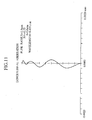
- FIG. 16 is a longitudinal aberration diagram of Example 5-1
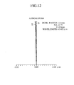
- FIG.17 is an astigmatism diagram.
- the wavefront aberration on the axis is small as 0.01 ⁇ , and it can be said that there is practically no aberration.
- the wavefront aberration is 0.056 ⁇ with respect to the out-of-axis incident light beam having the incidence angle of 0.5 degree with respect to the optical axis, and this similarly indicates the satisfactory characteristic.
- the wavefront aberration is 0.030 ⁇ , and a slight increase of aberration is seen, but there is no practical problem. That is, the objective lens 221 has a manufacturing tolerance which can sufficiently bear the mass production.
- the operation distance is 0.71 mm, and this is a sufficiently large value.
- Table 24 Specifications on lens Designed wavelength 405 nm NA 0.85 Focal distance 2.20 mm Entrance pupil diameter 3.74 mm
- Table 25 Designed values of lens Surface number Surface shape Radius Thickness Glass (Refractive index) Conic constant 1 Aspheric surface 1.8121 3.10 NBF1 (1.76898499) -0.33718 2 Aspheric surface -6.5076 0.41 - -845.6516 3 - Infinity 0.09 POLYCARB (1.62230752) - 4 - Infinity 0.01 ACRYLIC (1.50650420) - Image surface - - - - - - - - - - -
- the third and fourth surfaces indicate the respective surfaces of the transmission layer of the optical disk 223 (see FIG.15).
- the unit of radius or thickness is mm.
- aspheric coefficients of the first and second surfaces are shown in Tables 26, 27.
- Second surface Coefficient A4 of r 4 0.061449 Coefficient A6 of r 6 -0.13996 Coefficient A8 of r 8 0.12867 Coefficient A10 of r 10 -0.043733
- FIG.18 is a longitudinal aberration diagram of Example 5-2
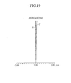
- FIG.19 is an astigmatism diagram.
- the axial wavefront aberration is 0.006 ⁇ , and it can be said that there is substantially no aberration.
- the out-of-axis wavefront aberration is 0.007 ⁇ with respect to the out-of-axis incident light beam having the incidence angle of 0.5 degree, and this indicates a practically satisfactory characteristic.
- the out-of-axis wavefront aberration is slightly larger than that of Example 5-1. This is because the numerical aperture (0.85) of Example 5-2 is larger than that (0.8) of Example 5-1.
- this objective lens also has a manufacturing tolerance which can bear mass production. Moreover, the operation distance of the objective lens 221 is 0.41 mm, and the lens has a practically sufficient broad value.
- the objective lens for the optical disk superior in the best image surface chromatic aberration characteristic and out-of-axis aberration characteristic, can be realized.
- the objective lens which is constituted of the single lens having a numerical aperture of 0.7 to 0.8, which can be used in the optical disk having a 0.3 mm or thinner reproducing transmission layer, whose eccentricity tolerance is in a manufacturable range with respect to the light having a wavelength of about 400 nm, and which has satisfactory axial and out-of-axis aberration characteristics and a broad operation distance.
- the objective lens which is constituted of the single lens having a numerical aperture of 0.78 or more, which can be used in the optical disk having a 0.3 mm or thinner reproducing transmission layer, whose eccentricity tolerance is in a manufacturable range with respect to the light having a wavelength of about 400 nm, and which has satisfactory axial and out-of-axis aberration characteristics and a broad operation distance.
Landscapes
- Physics & Mathematics (AREA)
- Optics & Photonics (AREA)
- General Physics & Mathematics (AREA)
- Lenses (AREA)
Applications Claiming Priority (6)
| Application Number | Priority Date | Filing Date | Title |
|---|---|---|---|
| JP2000350144A JP2002156579A (ja) | 2000-11-16 | 2000-11-16 | 光ディスク用対物レンズ |
| JP2000350144 | 2000-11-16 | ||
| JP2001230651 | 2001-07-30 | ||
| JP2001230652 | 2001-07-30 | ||
| JP2001230652 | 2001-07-30 | ||
| JP2001230651 | 2001-07-30 |
Publications (2)
| Publication Number | Publication Date |
|---|---|
| EP1209490A2 true EP1209490A2 (fr) | 2002-05-29 |
| EP1209490A3 EP1209490A3 (fr) | 2004-10-06 |
Family
ID=27345206
Family Applications (1)
| Application Number | Title | Priority Date | Filing Date |
|---|---|---|---|
| EP01126496A Withdrawn EP1209490A3 (fr) | 2000-11-16 | 2001-11-12 | Lentille d'objectif pour disque optique |
Country Status (4)
| Country | Link |
|---|---|
| US (1) | US20020097661A1 (fr) |
| EP (1) | EP1209490A3 (fr) |
| KR (1) | KR100506565B1 (fr) |
| CN (1) | CN1354376A (fr) |
Cited By (1)
| Publication number | Priority date | Publication date | Assignee | Title |
|---|---|---|---|---|
| WO2004021065A1 (fr) * | 2002-08-28 | 2004-03-11 | Konica Minolta Holdings, Inc. | Lentille d'objectif pour dispositif de lecture optique, dispositif de lecture optique et dispositif d'enregistrement/de reproduction d'informations optiques |
Families Citing this family (8)
| Publication number | Priority date | Publication date | Assignee | Title |
|---|---|---|---|---|
| JP2003337281A (ja) * | 2002-05-17 | 2003-11-28 | Minolta Co Ltd | 光ピックアップ用の対物レンズ |
| CN100585705C (zh) * | 2002-08-28 | 2010-01-27 | 柯尼卡美能达控股株式会社 | 光学拾取设备的物镜、光学拾取设备和光学信息记录/再现设备 |
| US7209428B2 (en) * | 2003-06-05 | 2007-04-24 | Pentax Corporation | Optical system of optical pick-up |
| CN100462772C (zh) * | 2005-04-01 | 2009-02-18 | 鸿富锦精密工业(深圳)有限公司 | 非球面镜片 |
| CN100426037C (zh) * | 2005-04-07 | 2008-10-15 | 鸿富锦精密工业(深圳)有限公司 | 非球面会聚镜片 |
| US8089705B2 (en) * | 2007-04-23 | 2012-01-03 | Hoya Corporation | Objective lens for optical pick-up |
| WO2016203748A1 (fr) * | 2015-06-15 | 2016-12-22 | 日本電気株式会社 | Procédé de conception de lentille à gradient d'indice et dispositif d'antenne l'utilisant |
| CN112904463A (zh) * | 2021-02-25 | 2021-06-04 | 南昌欧菲光电技术有限公司 | 红外镜头、成像模组及测温仪器 |
Family Cites Families (17)
| Publication number | Priority date | Publication date | Assignee | Title |
|---|---|---|---|---|
| US5105408A (en) * | 1988-05-12 | 1992-04-14 | Digital Equipment Corporation | Optical head with flying lens |
| US4927247A (en) * | 1988-05-13 | 1990-05-22 | Matsushita Electric Industrial Co., Ltd. | Objective lens for optical disk system and optical head using the same |
| JPH04163510A (ja) * | 1990-10-29 | 1992-06-09 | Konica Corp | 光ディスク用対物レンズ |
| US5835473A (en) * | 1996-01-17 | 1998-11-10 | Asahi Glass Company Ltd. | Optical pick-up, optical data recording apparatus and objective lens for optical data recording material |
| JPH09311271A (ja) * | 1996-05-20 | 1997-12-02 | ソニー株式会社 | 対物レンズ及び光学ピックアップ装置 |
| MY114470A (en) * | 1996-12-16 | 2002-10-31 | Matsushita Electric Industrial Co Ltd | Light pickup |
| WO1999059148A2 (fr) * | 1998-05-13 | 1999-11-18 | Koninklijke Philips Electronics N.V. | Dispositif de lecture optique d'un support d'enregistrement |
| US6349083B1 (en) * | 1998-07-13 | 2002-02-19 | Konica Corporation | Near field type optical disk recording reproducing apparatus, optical information recording medium recording reproducing apparatus, pickup apparatus, objective lens |
| JP2001013406A (ja) * | 1999-06-30 | 2001-01-19 | Victor Co Of Japan Ltd | 対物レンズ及びこれを用いた光ピックアップ装置 |
| TW504582B (en) * | 1999-09-01 | 2002-10-01 | Konishiroku Photo Ind | Objective lens for pickup and light pickup apparatus |
| JP2001297471A (ja) * | 2000-02-08 | 2001-10-26 | Asahi Optical Co Ltd | 光ピックアップ用対物光学系 |
| JP2001235678A (ja) * | 2000-02-23 | 2001-08-31 | Sony Corp | 対物レンズ、光学ピックアップ装置及び光ディスク装置 |
| EP1154417B1 (fr) * | 2000-05-12 | 2012-05-09 | Konica Minolta Opto, Inc. | Dispositif de lecture optique |
| JP2002184040A (ja) * | 2000-12-15 | 2002-06-28 | Pioneer Electronic Corp | 光ディスク |
| JP4817035B2 (ja) * | 2001-05-09 | 2011-11-16 | コニカミノルタホールディングス株式会社 | 対物レンズ、光ピックアップ装置、及び記録・再生装置 |
| JP3794940B2 (ja) * | 2001-06-19 | 2006-07-12 | 株式会社日立製作所 | 対物レンズ光学系、光ヘッド及び光情報再生装置 |
| JP4817036B2 (ja) * | 2001-06-20 | 2011-11-16 | コニカミノルタホールディングス株式会社 | 対物レンズ、光ピックアップ装置及び記録・再生装置 |
-
2001
- 2001-11-01 KR KR10-2001-0067779A patent/KR100506565B1/ko not_active Expired - Lifetime
- 2001-11-02 CN CN01136883A patent/CN1354376A/zh active Pending
- 2001-11-12 EP EP01126496A patent/EP1209490A3/fr not_active Withdrawn
- 2001-11-14 US US09/987,389 patent/US20020097661A1/en not_active Abandoned
Cited By (2)
| Publication number | Priority date | Publication date | Assignee | Title |
|---|---|---|---|---|
| WO2004021065A1 (fr) * | 2002-08-28 | 2004-03-11 | Konica Minolta Holdings, Inc. | Lentille d'objectif pour dispositif de lecture optique, dispositif de lecture optique et dispositif d'enregistrement/de reproduction d'informations optiques |
| US7920456B2 (en) | 2002-08-28 | 2011-04-05 | Konica Minolta Holdings, Inc. | Objective lens for optical pickup device, optical pickup device and optical information recording/reproducing apparatus |
Also Published As
| Publication number | Publication date |
|---|---|
| CN1354376A (zh) | 2002-06-19 |
| US20020097661A1 (en) | 2002-07-25 |
| KR20020038476A (ko) | 2002-05-23 |
| EP1209490A3 (fr) | 2004-10-06 |
| KR100506565B1 (ko) | 2005-08-10 |
Similar Documents
| Publication | Publication Date | Title |
|---|---|---|
| JP3932578B2 (ja) | 対物レンズ及び光学ピックアップ装置 | |
| US20020186476A1 (en) | Optical system for optical disk, optical head unit for optical disk, and optical drive unit | |
| KR101039021B1 (ko) | 대물 렌즈, 광 픽업 장치, 광 기록·재생 장치 | |
| CN101000780B (zh) | 物镜、聚光光学系统、光拾取器装置以及记录·再生装置 | |
| KR101061347B1 (ko) | 광픽업 장치용 대물 렌즈, 광픽업 장치 및 광정보 기록 재생 장치 | |
| JP2002303787A (ja) | 対物レンズおよびその製造誤差の補正方法並びに該対物レンズを用いた光ピックアップ装置 | |
| US6556534B2 (en) | Objective lens and optical device | |
| KR20020096939A (ko) | 대물 렌즈, 광픽업 장치 및 기록 및/또는 재생 장치 | |
| JPH05100161A (ja) | 光デイスク用対物レンズ | |
| US20020097661A1 (en) | Objective lens for optical disk | |
| JP3826819B2 (ja) | 光ピックアップ装置 | |
| JPS61163308A (ja) | 屈折率分布型単レンズ | |
| JP4296868B2 (ja) | 光ピックアップ装置用の光学系、光ピックアップ装置及び光情報記録再生装置 | |
| JP2001337269A (ja) | 色収差補正用光学素子及び光学ピックアップ装置 | |
| JP2002156579A (ja) | 光ディスク用対物レンズ | |
| KR20040105579A (ko) | 광 픽업 장치용의 광학 소자, 광 픽업 장치, 광 정보 기록재생 장치, 광 픽업 장치용의 수차 보정 소자 및 광 픽업장치용의 집광 렌즈 | |
| JP4789169B2 (ja) | 色収差補正用光学素子、光学系、光ピックアップ装置及び記録・再生装置 | |
| JP4232188B2 (ja) | 光ピックアップ装置用の対物レンズ、光ピックアップ装置及び光情報記録再生装置 | |
| CN101452110B (zh) | 物镜、光拾取装置、光记录介质记录及/或再生装置 | |
| JPH11258497A (ja) | 対物レンズ光学系 | |
| US8345356B2 (en) | Objective lens, optical pickup device, and optical recording/reproducing apparatus | |
| JP4259052B2 (ja) | 光ピックアップ装置、光ディスク記録再生装置及び光ディスク再生装置 | |
| JP4488334B2 (ja) | 光ディスク用対物レンズ | |
| JPH02245715A (ja) | 低分散ガラスモールド非球面単レンズ | |
| JP2003294914A (ja) | 接合レンズ及びこれを用いた光ヘッド装置 |
Legal Events
| Date | Code | Title | Description |
|---|---|---|---|
| PUAI | Public reference made under article 153(3) epc to a published international application that has entered the european phase |
Free format text: ORIGINAL CODE: 0009012 |
|
| AK | Designated contracting states |
Kind code of ref document: A2 Designated state(s): AT BE CH CY DE DK ES FI FR GB GR IE IT LI LU MC NL PT SE TR |
|
| AX | Request for extension of the european patent |
Free format text: AL;LT;LV;MK;RO;SI |
|
| PUAL | Search report despatched |
Free format text: ORIGINAL CODE: 0009013 |
|
| AK | Designated contracting states |
Kind code of ref document: A3 Designated state(s): AT BE CH CY DE DK ES FI FR GB GR IE IT LI LU MC NL PT SE TR |
|
| AX | Request for extension of the european patent |
Extension state: AL LT LV MK RO SI |
|
| RIC1 | Information provided on ipc code assigned before grant |
Ipc: 7G 02B 3/02 B Ipc: 7G 11B 7/135 A |
|
| 17P | Request for examination filed |
Effective date: 20040923 |
|
| 17Q | First examination report despatched |
Effective date: 20041126 |
|
| AKX | Designation fees paid |
Designated state(s): DE FR GB |
|
| STAA | Information on the status of an ep patent application or granted ep patent |
Free format text: STATUS: THE APPLICATION IS DEEMED TO BE WITHDRAWN |
|
| 18D | Application deemed to be withdrawn |
Effective date: 20060223 |