EP1211029A2 - Dispositif pour fixer une cheville, en particulier une cheville en métal pourvue d'un cône d'expansion - Google Patents
Dispositif pour fixer une cheville, en particulier une cheville en métal pourvue d'un cône d'expansion Download PDFInfo
- Publication number
- EP1211029A2 EP1211029A2 EP20010116369 EP01116369A EP1211029A2 EP 1211029 A2 EP1211029 A2 EP 1211029A2 EP 20010116369 EP20010116369 EP 20010116369 EP 01116369 A EP01116369 A EP 01116369A EP 1211029 A2 EP1211029 A2 EP 1211029A2
- Authority
- EP
- European Patent Office
- Prior art keywords
- dowel
- guide shaft
- housing
- firing pin
- receptacle
- Prior art date
- Legal status (The legal status is an assumption and is not a legal conclusion. Google has not performed a legal analysis and makes no representation as to the accuracy of the status listed.)
- Withdrawn
Links
Images


Classifications
-
- B—PERFORMING OPERATIONS; TRANSPORTING
- B25—HAND TOOLS; PORTABLE POWER-DRIVEN TOOLS; MANIPULATORS
- B25B—TOOLS OR BENCH DEVICES NOT OTHERWISE PROVIDED FOR, FOR FASTENING, CONNECTING, DISENGAGING, OR HOLDING
- B25B31/00—Hand tools for applying fasteners
Definitions
- the invention relates to a device for setting a dowel, in particular a metal dowel with an indirect expansion cone, with the Features according to the preamble of protection claim 1.
- Such dowels are usually inserted into a pre-formed dowel hole or hit, with a necessary lowering of the front or face of a dowel opposite a fastening, wall or ceiling surface relatively imprecise by means of a rod-shaped object is made. Then the intended mounting cone is by means of of a suitable tool.
- the dowel is often in its mounting depth changed, leading to relative mounting problems can lead, especially if a dowel is used in relation to one coming fastening screw, too deep or too high in one Dowel hole sits, and the fastening screw too short or too is long.
- the invention has for its object a device for setting a dowel, especially a metal dowel with an indirect one Spreading cone to create the disadvantages of previous handling technology eliminated when installing such dowels and by means of which the dowels extremely precise in pre-formed dowel holes, based on the distance the dowel front or face to a fastening, wall or ceiling surface, sunk to each other in the respective dowel hole, non-positive are settable.
- the firing pin is said to be against an uncontrolled one Actuation when placing a dowel can be secured.
- An advantage of the new device is not only the practical structure the whole with a handy, handy housing and one in the housing axially mounted firing pin, which is preferably provided Driving bolt acted on, but also on one side of a dowel holder arranged, cylindrical and coaxial guide shaft, whose outer diameter is the inner diameter of a dowel hole corresponds, as well as the one-sided and coaxially arranged on the guide shaft Threaded shaft for releasably screwing on an anchor to be placed.
- the dowel holder is expediently arranged and exchangeable stored. It is therefore advantageously possible, not only suitable ones i.e. appropriately dimensioned dowel holders for differently designed dowels or other assembly means, for example for nails to be countersunk, use, but also one, the intended inner diameter of one Dowel holes corresponding to the guide shaft diameter on the device to install.
- the handy and expedient operation of the device is also advantageous and the simple interchangeability provided there, not only the dowel holder, but also the driving pin against others accordingly appropriate tools.
- Another significant advantage is the rationally feasible technical Expandability of the new device, particularly with regard to the loading the firing pin, which instead of a handy loading by means of a hammer, also mechanically, for example hydro / pneumatic or electromagnetic, electromotive or piezzoelectric, can be effected so that the device is also useful in a mechanical or industrial equipment can be used.
- the firing pin is indirectly manually, by means of a locking bolt, can be locked so that the firing pin of the expansion cone Do not apply the anchor during this manually controlled locking phase can, even if the firing pin is accidentally struck.
- the intended and on the new device rationally adjustable setting depth stop both in a known manner via a thread on the front guide shaft and / or by means of on the setting depth stop provided new adjustment spring, which can be released non-positive engagement with the thread on the guide flange
- new adjustment spring which can be released non-positive engagement with the thread on the guide flange
- Quick adjustment of the setting depth stop allows by this adjustment spring is mounted radially avoidable, so that the setting depth stop in the respective required setting depth on the leadership shaft is screwable or adjustable.
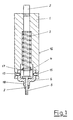
- the device shown in FIGS. 1 to 7 consists in detail from a, expediently cylindrical, housing 1, which in particular is made of a metallic material in which coaxial running one, in particular cylindrical rod-shaped firing pin 2 longitudinally displaceable is stored.
- 3 denotes a compression spring force that supported on a limiting disk 4 and the firing pin 2 on a in cross section in particular T-shaped, driving pin 5 presses.
- the boundary disc 4 is in turn engaged by the firing pin 2 standing, lock washer 17 fixed in position.
- the driving pin 5 is in a so-called dowel holder 6 coaxial to the firing pin 2 longitudinally stored.
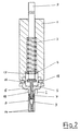
- FIG. 7 denotes a threaded shaft, which is on one side on the dowel holder 6 is arranged and onto which a metal dowel 8 is screwed in accordance with the application is arranged, as can be seen in more detail in FIG. 2.
- 9 designated there the so-called expansion cone in the metal dowel 8 on its Head side 10 of the driving pin 5 under the action of the compression spring force 3 rests.
- 18 denotes a one-sided arrangement on the dowel receptacle 6, cylindrical, guiding shaft of the device not only leads precisely in a dowel hole 11, but also its length on the front support 13 of the dowel holder 6, a measure for is the installation depth of a dowel 8 in a dowel hole 11.
- Metal dowel 8 is now in a pre-formed dowel hole 11, for example a masonry 12, expediently up to the front Pad 13 of the dowel holder 6 inserted.
- the firing pin 2 is acted upon and via the indirect driving pin 5 the expansion cone 9 is pressed into the metal dowel 8, so that the mirror image dowel lamellae 14 adjacent to one another and arranged on one side pressed non-releasably against the wall of the dowel hole 11 become.
- the device is unscrewed from the metal dowel 8 unscrewed.
- the dowel holder 6 is detachable arranged on the housing 1 of the device. That it is under the innovation provided that the dowel receptacle 6, in particular in the area of 1 to 4 shown threaded shaft 7 have an education can with the new device not only other dowels regarding their To be able to set mounting depth in a dowel hole 11 precisely, but in order with the new device, for example, also nails to a front of assembly 20 to sink precisely.
- the threaded shaft 7 on the dowel holder 6 may be completely absent for such an application or one have suitable training. It is also envisaged that the length the guide shaft 18 on the dowel holder 6, the respective requirements accordingly, different lengths can be formed.
- the interchangeable Dowel holder 6 is expediently by means of screws 15 in Housing 1 releasably attached non-positively.
- the peripheral jacket 16 of the housing 1 of the device is expedient easy to get hold of.
- the peripheral jacket 16 can be cylindrical, circular or multi-faceted.
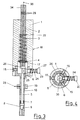
- 3 and 4 show the new device with the appropriate manual controllable and / or actuable mechanical locking of the driving pin 5 and / or firing pin 2, which is effectively arranged on the housing 1.
- 3 designated the compression spring force mounted coaxially on the firing pin 2, which is under spring tension with one end side on the Housing paragraph 22 and with its other end on the, with the firing pin 2 by a locking washer 17 fixed-position limiting disk 4 supports and presses the firing pin 2 on the driving pin 5.
- 7 designated there the threaded shaft and 18 indicates the guide shaft, which is arranged on one side on the dowel holder 6.
- 8 shows the metal dowel, the use-compliant on the threaded shaft 7 of the dowel holder 6 is screwed on.
- 9 marks the expansion cone of the metal dowel 8.
- 15 designated Screws, for releasably non-positive fastening of the dowel holder 6 in the housing 1.
- the locking of the driving pin 5 is from a manually actable Locking bolt 23 formed, which is perpendicular to the housing axis 35 in the housing 1 is mounted and against the action of a compression spring force 24 can be directly or indirectly engaged with the driving pin 5 is.
- the locking bolt 23 is expediently in the manual loading area formed outside the housing 1 as a handy push button and covered with a corresponding push-button shaped part.
- control marks 29 denotes so-called control marks in the area of the housing 1 Functionally outstanding, loadable, firing pin end 34. It is by means of these groove-like, continuously rotating control marks 29 a device user possible on the one hand, the expansion cone 9 at Insert a dowel 8 precisely into the dowel 8. on the other hand enable these control marks 29 indirectly the press-in position of the Determine or correct the expansion cone 9 in a dowel 8. Conveniently, are several for optimal position control of the expanding keg 9 Control marks 29 are provided.
- the Set depth stop 19 is for non-positive position fixing on the thread 21 of the dowel receptacle 6 expediently with an adjusting spring 28 equipped in a slot-shaped transverse bore 31 in the setting depth stop 19 is arranged and stored, as shown in FIG. 5 in more detail can be seen.
- Fig. 5 denotes the setting depth stop with the adjusting spring 28, which is expediently designed as a shaped spring and with the there straight spring part 30 via a transverse bore 31 with the Set depth stop 19 is engaged.
- the other spring end 32 is as Molded part is formed and lies in the assembled state on the setting depth stop 19, expediently on an outer screw edge 33 of the setting depth stop 19 resiliently non-positive.
- the dowel 8 is rational, simple and precise, covered on the assembly front 20 of masonry 12, on the required Setting depth can be positioned in the dowel hole 11.
- 28 denotes the adjusting spring of the setting depth stop 19, which have already been explained in more detail above Cross bore 31 is mounted.
- FIG. 7 shows a provided guide shaft extension piece 18.1, the one side with a threaded shaft 7.1 for releasably non-positive Screwing a dowel, not shown, is provided and that on the opposite end side with a one-sided internal thread 36, for releasable non-positive screwing onto the threaded shaft 7 of the guide shaft 18 of FIGS. 1 to 6.
- 5.1 indicates an im Guide shaft extension piece 18.1 axially slidably mounted Driving pin with a driving pin plate provided on one side and in one piece 26.1.
- the outer diameter of the guide shaft extension 18.1 suitably corresponds to the outside diameter of the guide shaft 18 of the dowel holder 6 from FIGS. 1 to 4 and 6.
- the spatial Length of the guide shaft extension piece 18.1 and its material is arbitrary.
- Thread 21 provided for the engagement of the axially continuously adjustable Setting depth stop 19 from FIGS. 3 to 6.
- a thread 21 for height adjustment of the setting depth stop 19 can also be mutually stepped grooves or endless grooves on the circumference of the guide shaft extension 18.1 may be provided.
- Such a guide shaft extension piece 18.1 may be required if, for example, on the front of a masonry 12 an insulation layer, not shown here, or another Support is provided and a dowel 8 through the insulation layer or other support is to be placed in the masonry 12.
- the adjustable setting depth stop 19 can expediently be used as a threaded screw be trained.
- the leadership shaft is 18th provided with a thread 21 in particular over its entire axial length.
- the guide shaft 18 over its length is cylindrical smooth, and that the setting depth stop 19 as a collar with a corresponding locking device, is in particular in the form of a locking screw.
- the device It is in training for rational and economic use the device provided that the firing pin 2 hydro / pneumatic or electromagnetically or electromotively or piezzoelectrically becomes.
- the device can be equipped with an appropriate externally powered hammer mill equipped detachable or non-detachable be manually controllable. It is also provided that the new device as part of a mechanical device is expedient and economical to use.
Landscapes
- Engineering & Computer Science (AREA)
- Mechanical Engineering (AREA)
- Dowels (AREA)
Applications Claiming Priority (4)
| Application Number | Priority Date | Filing Date | Title |
|---|---|---|---|
| DE20012596U DE20012596U1 (de) | 2000-07-18 | 2000-07-18 | Vorrichtung zum Setzen eines Dübels, insbesondere eines Metall-Dübels mit einem mittelbaren Spreizkegel |
| DE20012596U | 2000-07-18 | ||
| DE20103341U | 2001-02-26 | ||
| DE20103341U DE20103341U1 (de) | 2001-02-26 | 2001-02-26 | Vorrichtung zum Setzen eines Dübels, insbesondere eines Metall-Dübels |
Publications (1)
| Publication Number | Publication Date |
|---|---|
| EP1211029A2 true EP1211029A2 (fr) | 2002-06-05 |
Family
ID=26056405
Family Applications (1)
| Application Number | Title | Priority Date | Filing Date |
|---|---|---|---|
| EP20010116369 Withdrawn EP1211029A2 (fr) | 2000-07-18 | 2001-07-06 | Dispositif pour fixer une cheville, en particulier une cheville en métal pourvue d'un cône d'expansion |
Country Status (1)
| Country | Link |
|---|---|
| EP (1) | EP1211029A2 (fr) |
Cited By (3)
| Publication number | Priority date | Publication date | Assignee | Title |
|---|---|---|---|---|
| FR2984201A1 (fr) * | 2011-12-15 | 2013-06-21 | Peugeot Citroen Automobiles Sa | Dispositif de montage au maillet d'une goupille dans un logement pre perce d'une piece mecanique |
| EP2614928A1 (fr) * | 2012-01-16 | 2013-07-17 | UIP GmbH & Co. KG | Outil pour enfoncer des organes de fixation, procédé de pose d'un élément de fixation pouvant être ancré par enfoncement en utilisant un outil pour enfoncer des organes de fixation ainsi que procédé de montage d'un outil pour enfoncer des organes de fixation |
| EP4613430A1 (fr) * | 2024-03-05 | 2025-09-10 | fischerwerke GmbH & Co. KG | Outil de pose destiné à poser un ancrage d'enfoncement |
-
2001
- 2001-07-06 EP EP20010116369 patent/EP1211029A2/fr not_active Withdrawn
Cited By (4)
| Publication number | Priority date | Publication date | Assignee | Title |
|---|---|---|---|---|
| FR2984201A1 (fr) * | 2011-12-15 | 2013-06-21 | Peugeot Citroen Automobiles Sa | Dispositif de montage au maillet d'une goupille dans un logement pre perce d'une piece mecanique |
| EP2614928A1 (fr) * | 2012-01-16 | 2013-07-17 | UIP GmbH & Co. KG | Outil pour enfoncer des organes de fixation, procédé de pose d'un élément de fixation pouvant être ancré par enfoncement en utilisant un outil pour enfoncer des organes de fixation ainsi que procédé de montage d'un outil pour enfoncer des organes de fixation |
| WO2013107438A3 (fr) * | 2012-01-16 | 2013-09-12 | Uip Gmbh & Co. Kg | Outil d'enfoncement, procédé d'installation d'un élément de fixation pouvant être ancré par enfoncement au moyen d'un outil d'enfoncement et procédé de montage d'un outil d'enfoncement |
| EP4613430A1 (fr) * | 2024-03-05 | 2025-09-10 | fischerwerke GmbH & Co. KG | Outil de pose destiné à poser un ancrage d'enfoncement |
Similar Documents
| Publication | Publication Date | Title |
|---|---|---|
| DE19982996B4 (de) | Einstellbare Schnellwechsel-Stanzwerkzeuganordnung | |
| DE4432783A1 (de) | Befestigungselement mit Nagel und Vorspannelement | |
| DE2817640C2 (de) | Prägekopf für ein Bolzenschußgerät | |
| DE2908034A1 (de) | Schnellwechselvorrichtung fuer fraeskopfwerkzeuge | |
| WO1983003215A1 (fr) | Chassis-support pour outils de tours | |
| DE3719010A1 (de) | Aufspannvorrichtung fuer werkstuecke | |
| EP1211029A2 (fr) | Dispositif pour fixer une cheville, en particulier une cheville en métal pourvue d'un cône d'expansion | |
| DE3418981A1 (de) | Stempel-gesenk-anordnung fuer eine pulververdichterpresse | |
| DE19904849A1 (de) | Vorrichtung zum Eintreiben von nagelartigen Befestigungsstiften | |
| EP0670200A1 (fr) | Magasin de chargement d'attaches pour un outil de scellement actionné par poudre explosive | |
| EP0007980A1 (fr) | Organe de fixation à tige s'évasant, outil et procédé de préparation des trous pour de tels organes de fixation | |
| DE20012596U1 (de) | Vorrichtung zum Setzen eines Dübels, insbesondere eines Metall-Dübels mit einem mittelbaren Spreizkegel | |
| DE10115926C2 (de) | Dübelsetzvorrichtung | |
| DE19938923C2 (de) | Vorrichtung zum Einschlagen von Nägeln | |
| DE3518755A1 (de) | Vorrichtung zum punktgenauen anbohren mit einer handbohrmaschine | |
| DE102007039141A1 (de) | Setzwerkzeug | |
| DE20103341U1 (de) | Vorrichtung zum Setzen eines Dübels, insbesondere eines Metall-Dübels | |
| DE1847572U (de) | Befestigungsvorrichtung mit duebel und klemmplatte. | |
| DE3238975C2 (fr) | ||
| DE19737807B4 (de) | Schneidwerkzeug mit einem konischen Hauptkörper | |
| DE4211482C2 (de) | Markierungsvorrichtung | |
| AT393100B (de) | Vorrichtung zum befestigen eines unterlagsteiles fuer ein honelement an einem tragteil | |
| DE8902472U1 (de) | Hohlbohrer | |
| DE29619183U1 (de) | Vorrichtung zur Befestigung von Dach- oder Fassadenplatten an nagelbarem Untergrund | |
| AT208313B (de) | Setzgerät |
Legal Events
| Date | Code | Title | Description |
|---|---|---|---|
| PUAI | Public reference made under article 153(3) epc to a published international application that has entered the european phase |
Free format text: ORIGINAL CODE: 0009012 |
|
| AK | Designated contracting states |
Kind code of ref document: A2 Designated state(s): AT BE CH CY DE DK ES FI FR GB GR IE IT LI LU MC NL PT SE TR |
|
| AX | Request for extension of the european patent |
Free format text: AL;LT;LV;MK;RO;SI |
|
| STAA | Information on the status of an ep patent application or granted ep patent |
Free format text: STATUS: THE APPLICATION HAS BEEN WITHDRAWN |
|
| 18W | Application withdrawn |
Effective date: 20030701 |