EP1211113A2 - Dispositif d'entraínement pour toit coulissant de véhicule - Google Patents
Dispositif d'entraínement pour toit coulissant de véhicule Download PDFInfo
- Publication number
- EP1211113A2 EP1211113A2 EP01125520A EP01125520A EP1211113A2 EP 1211113 A2 EP1211113 A2 EP 1211113A2 EP 01125520 A EP01125520 A EP 01125520A EP 01125520 A EP01125520 A EP 01125520A EP 1211113 A2 EP1211113 A2 EP 1211113A2
- Authority
- EP
- European Patent Office
- Prior art keywords
- drive
- toothed belt
- drive device
- pinion
- toothed
- Prior art date
- Legal status (The legal status is an assumption and is not a legal conclusion. Google has not performed a legal analysis and makes no representation as to the accuracy of the status listed.)
- Granted
Links
- 238000004804 winding Methods 0.000 claims abstract description 31
- 230000006835 compression Effects 0.000 claims description 5
- 238000007906 compression Methods 0.000 claims description 5
- 230000000295 complement effect Effects 0.000 claims description 4
- 238000006073 displacement reaction Methods 0.000 claims description 2
- 238000010276 construction Methods 0.000 description 3
- 238000011161 development Methods 0.000 description 2
- 230000018109 developmental process Effects 0.000 description 2
- 238000004519 manufacturing process Methods 0.000 description 2
- 239000000463 material Substances 0.000 description 2
- 239000002184 metal Substances 0.000 description 2
- 230000003014 reinforcing effect Effects 0.000 description 2
- 238000005452 bending Methods 0.000 description 1
- 230000005540 biological transmission Effects 0.000 description 1
- 210000001520 comb Anatomy 0.000 description 1
- 230000005284 excitation Effects 0.000 description 1
- 239000011521 glass Substances 0.000 description 1
Images


Classifications
-
- B—PERFORMING OPERATIONS; TRANSPORTING
- B60—VEHICLES IN GENERAL
- B60J—WINDOWS, WINDSCREENS, NON-FIXED ROOFS, DOORS, OR SIMILAR DEVICES FOR VEHICLES; REMOVABLE EXTERNAL PROTECTIVE COVERINGS SPECIALLY ADAPTED FOR VEHICLES
- B60J7/00—Non-fixed roofs; Roofs with movable panels, e.g. rotary sunroofs
- B60J7/02—Non-fixed roofs; Roofs with movable panels, e.g. rotary sunroofs of sliding type, e.g. comprising guide shoes
- B60J7/04—Non-fixed roofs; Roofs with movable panels, e.g. rotary sunroofs of sliding type, e.g. comprising guide shoes with rigid plate-like element or elements, e.g. open roofs with harmonica-type folding rigid panels
- B60J7/057—Driving or actuating arrangements e.g. manually operated levers or knobs
- B60J7/0573—Driving or actuating arrangements e.g. manually operated levers or knobs power driven arrangements, e.g. electrical
-
- F—MECHANICAL ENGINEERING; LIGHTING; HEATING; WEAPONS; BLASTING
- F16—ENGINEERING ELEMENTS AND UNITS; GENERAL MEASURES FOR PRODUCING AND MAINTAINING EFFECTIVE FUNCTIONING OF MACHINES OR INSTALLATIONS; THERMAL INSULATION IN GENERAL
- F16C—SHAFTS; FLEXIBLE SHAFTS; ELEMENTS OR CRANKSHAFT MECHANISMS; ROTARY BODIES OTHER THAN GEARING ELEMENTS; BEARINGS
- F16C1/00—Flexible shafts; Mechanical means for transmitting movement in a flexible sheathing
- F16C1/10—Means for transmitting linear movement in a flexible sheathing, e.g. "Bowden-mechanisms"
- F16C1/12—Arrangements for transmitting movement to or from the flexible member
- F16C1/16—Arrangements for transmitting movement to or from the flexible member in which the end-piece is guided rectilinearly
-
- Y—GENERAL TAGGING OF NEW TECHNOLOGICAL DEVELOPMENTS; GENERAL TAGGING OF CROSS-SECTIONAL TECHNOLOGIES SPANNING OVER SEVERAL SECTIONS OF THE IPC; TECHNICAL SUBJECTS COVERED BY FORMER USPC CROSS-REFERENCE ART COLLECTIONS [XRACs] AND DIGESTS
- Y10—TECHNICAL SUBJECTS COVERED BY FORMER USPC
- Y10T—TECHNICAL SUBJECTS COVERED BY FORMER US CLASSIFICATION
- Y10T74/00—Machine element or mechanism
- Y10T74/20—Control lever and linkage systems
- Y10T74/20396—Hand operated
- Y10T74/20402—Flexible transmitter [e.g., Bowden cable]
-
- Y—GENERAL TAGGING OF NEW TECHNOLOGICAL DEVELOPMENTS; GENERAL TAGGING OF CROSS-SECTIONAL TECHNOLOGIES SPANNING OVER SEVERAL SECTIONS OF THE IPC; TECHNICAL SUBJECTS COVERED BY FORMER USPC CROSS-REFERENCE ART COLLECTIONS [XRACs] AND DIGESTS
- Y10—TECHNICAL SUBJECTS COVERED BY FORMER USPC
- Y10T—TECHNICAL SUBJECTS COVERED BY FORMER US CLASSIFICATION
- Y10T74/00—Machine element or mechanism
- Y10T74/20—Control lever and linkage systems
- Y10T74/20396—Hand operated
- Y10T74/20402—Flexible transmitter [e.g., Bowden cable]
- Y10T74/2042—Flexible transmitter [e.g., Bowden cable] and hand operator
-
- Y—GENERAL TAGGING OF NEW TECHNOLOGICAL DEVELOPMENTS; GENERAL TAGGING OF CROSS-SECTIONAL TECHNOLOGIES SPANNING OVER SEVERAL SECTIONS OF THE IPC; TECHNICAL SUBJECTS COVERED BY FORMER USPC CROSS-REFERENCE ART COLLECTIONS [XRACs] AND DIGESTS
- Y10—TECHNICAL SUBJECTS COVERED BY FORMER USPC
- Y10T—TECHNICAL SUBJECTS COVERED BY FORMER US CLASSIFICATION
- Y10T74/00—Machine element or mechanism
- Y10T74/20—Control lever and linkage systems
- Y10T74/20396—Hand operated
- Y10T74/20402—Flexible transmitter [e.g., Bowden cable]
- Y10T74/20462—Specific cable connector or guide
Definitions
- the invention relates to a drive device for Motor vehicle sunroofs according to the preamble of Claim 1.
- motor vehicle sunroof or “sunroof” All constructions are intended for the purposes of the present invention include where at least one lid is one Roof opening of a motor vehicle adjustably assigned and is movable by means of the drive device. This includes Constructions in which the lid after lowering its Rear edge to release the roof opening under the rear fixed roof surface can be moved, but also so-called sunroofs, where the lid is also based on its close the roof opening position by a nearby its swivel axis provided for its front edge for exhibition can be pivoted over the fixed roof surface.
- All known drive devices of the aforementioned Type e.g. DE 38 03 816 A1, DE 38 09 949 A1, DE 195 31 514 C1 has in common that that over a hand crank gear or a Electric gear motor driven pinion with its teeth directly with the working windings of the drive cables engages like a rack and pinion drive. Because of the circular cross-sectional circumference of the wire working winding and the inevitable dimensional tolerances on the drive cables, the pinion and the guide elements for the drive cables can be in these known drive devices ideal tooth shape on the pinion, which a normal optimized Gearbox would correspond, not realize.
- the invention has for its object a drive device of the type mentioned at the beginning, with which uniform and low-noise displacement movements of the enables two drive cables without vibration excitation become.
- the internal teeth are advantageous here according to claim 2 of the toothed belt and the toothed pinion, while the external toothing of the toothed belt corresponds to the thread-like helix pitch of the wire working winding the drive cable has helical teeth. Due to the Straight toothing of toothed pinion and internal toothing of the toothed belt this meshing can be optimized.
- the external toothing the toothed belt can be the thread-like work winding adapt well and ensures a play-free Intervention, especially since this always takes place along straight line sections a plurality of teeth with the external teeth engage the working windings of the drive cables.
- the toothed belt is on a rotatably mounted Pulley deflected, resulting in only low friction losses.
- the roller can be a pinion have the corresponding toothing, i.e. as a pulley can also be another one that matches the drive pinion Pinions are used, but not itself is driven, but only by the driven toothed belt is rotated.
- the manufacture of an additional Partly, namely an toothless deflection roller, is not required this embodiment.
- a toothed or toothless deflection roller can but also a simple rounded according to claim 5 Use sliding surface over which the toothed belt is guided if this sliding surface is low Friction coefficient on the material of the timing belt is matched accordingly.
- timing belt is in the range for the engagement its external teeth with the working windings of the drive cables provided sections on sliding surfaces sliding is led. With this measure, the meshing between the external toothing of the toothed belt and the working windings the drive cable under all operating conditions ensured.
- the rotatably mounted Roller or the sliding surface and the support surfaces for the toothed belt attached to one between the two drive cables Support and guide element can be arranged.
- Electric motor drive can this support and guide element part of the Motor / transmission unit, as specified in claim 8.
- the tension of the toothed belt by means of a tensioning device is adjustable.
- the arrangement can also be corresponding Claim 10 be taken so that the tension of the Timing belt generated by a spring-loaded tensioner is. No adjustment work is required here.
- in series and mass production is guaranteed that when using the same springs from the drive device Drive device gives the toothed belt the same tension becomes.
- the clamping device as specified in claim 11 with the rotatably mounted roller or the rounded sliding surface, i.e. at Adjustment of the belt tension or by spring force directly acting on the roller or sliding surface.
- tensioning device specified in claim 12 has one parallel to the drive cables slidably guided on the support and guide element Cocking slide on which the roller is mounted or the rounded one Sliding surface is attached.
- tensioning device can be a rotating and according to claim 13 noticeable attached to the support and guide element Positioning eccentric cam can be provided on the of the role or the sliding surface of the side of the cocking slide is applied.
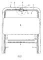
- the sunroof frame shown in Fig. 1 which in known Way can be pre-assembled in modules and for attachment a motor vehicle roof provided with a roof opening (not shown) essentially consists of a front frame cross part 1, two side frame parts 2 and 3 and possibly one of the side frame parts 2, 3 against each other stiffening middle cross section 4.
- On the two lateral frame parts 2, 3 are usually guide rails, at which one assigned to the roof opening Cover 5 is guided.
- the drive of the cover 5 for shifting movements and possibly swiveling movements Can be moved with pressure resistance in two in guide channels and / or pipes guided drive cable 6, each side of which Cover 5 is assigned a cable.
- the guide channels and / or tubes 7 and 8 are in Fig. 1 as well as the two Drive cable 6 only hinted at.
- the drive device 9 Approximately in the middle of the frame cross section 1 is the drive device 9, on the the invention relates and described in more detail below is.
- FIGS. 2 and 3 in conjunction with the sectional views of Figures 4 to 6 referenced.
- the drive device 9 has a Pinion 10, in the example shown by an electric gear motor 11 can be driven in both directions of rotation.
- the Drive pinion 10 is located in the middle between the two drive cables 6, the opposite in parallel to each other Guide channels 7, 8 are guided displaceably rigid.
- the drive cables are at least in the area of the drive device 9 6 in a guide profile 12 ( Figures 4 to 6) arranged, that in Figures 2 and 3 to simplify the drawing is not shown.
- Fig. 2 and also in the Figures 10 to 14 are the two drive cables 6 only with their correspondingly designated central axes.
- the upwardly open guide profile 12 is from the front Frame cross part 1 closed, as shown in Figures 4 to 6.
- the electric geared motor 11, with its drive shaft 13 for the pinion 10 through the lower web 14 of the Guide profile 12 is passed (Fig. 4), the guide profile 12 and the frame cross member 1 are by (not shown) Screws firmly connected to one another, as in FIG. 6 using the example of one of the mounting arrangements.
- an endless flexible and tensile toothed belt 18 is arranged, that of a plastic band with or without reinforcing insert can be shaped.
- the reinforcing insert can be act on a metal strip that is resistant to bending and which is connected to a suitable elastomeric plastic is encapsulated.
- the deposit gives the toothed belt 18 the required tensile strength at the same time and dimensional stability.
- On the inside is the Timing belt 18 with one of the teeth 19 of the pinion 10 complementary internal teeth 20 provided.
- On its outside the toothed belt 18 is provided with external toothing 21, which of the usual in such drive cables 6 helical working winding 22 from a round wire is complementary.
- the drive cable 6 with its working winding 22 is shown in length sections in FIGS. 3 and 9.
- the toothed belt 18 partially wraps around the pinion 10, namely in all the illustrated exemplary embodiments by an angle of 180 °, and is also with a corresponding wrap angle around a deflection roller 23 (FIGS. 2, 13, 14) or 23 '(Fig. 10, 12) or a rounded sliding surface 24 (Fig. 11) led around.
- the toothed belt 18 is in the looping area Pinion 10 with its internal teeth 20 constantly with the Teeth 19 of the pinion 10 held in engagement.
- the pinion 10 and the guide roller 23 or 23 'or the Sliding surface 24 are spaced from each other, so that the toothed belt 18 opposite straight line sections forms parallel to the drive cables 6.
- the external toothing 21 of the toothed belt 18 is constantly on these sections with the working windings 22 of the drive cable 6 in engagement held. Because of these engagement conditions of those involved Components of the drive device can be seen that a rotary drive of the pinion 10 depending on the direction of rotation the toothed belt 18 in one direction or the other entraining.
- the toothed belt 18 in turn takes the drive cable 6 with and moves them in the guide channels 7, 8 in opposite directions Shifting directions.
- the timing belt 18 also runs clockwise via the pinion 10 and the deflection roller 23 that with reference to Fig. 2 outer drive cable 6 to the right and the inner drive cable 6 shifted to the left.
- the external toothing 21 of the toothed belt 18, however, is corresponding the helix pitch of the working winding 22 of the Drive cable 6 helical teeth, as shown in Fig. 7.
- Out Fig. 7 in connection with the sectional views of the figures 4 to 6 is with regard to the toothing geometry of the external toothing 21 see the following.
- the outer surface 25 is in the straight line sections of the toothed belt 18 a flat surface, in which alternating Core recesses 26 and tooth recesses 27 different Size are molded.
- the core recesses 26 are the core diameter the drive cable 6 adapted while the tooth recesses 27 adapted to the outer diameter of the working winding 22 are.
- the axial distances between the tooth recesses 27 are defined by the "thread pitch" of the working winding 22, while the width b (see FIG. 7) of the tooth recesses 27 matched to the wire diameter of the working winding 22 is.
- Form the core recesses 26 and the tooth recesses 27 together the external toothing 21, which is approximately a negative shape the drive cable 6.
- the teeth of the external toothing 21 are due to the convex inclined ribs formed between two tooth recesses 27 are located.
- deflection roller 23 ' is on its outer surface 30 to support the internal toothing 20 of the toothed belt 18 cylindrical formed, the diameter of the deflection roller 23 ' about the root diameter of the toothing 19 of the pinion 10 corresponds.
- 10 is the Deflection roller 23 'in turn on one on the block of the electric gear motor 11 attached pin 29 rotatably mounted.
- the endless toothed belt 18 (18 ') according to the for the engagement between its external toothing 21 (21 ') and the working windings 22 the drive cable 6 provided sections of the rounded Slide surface 24, which is in the example shown extends over an angle of 180 ° and as a half cylinder surface is formed, the radius with the root radius the toothing 19 of the pinion 10 approximately coincides.
- the Toothed belt 18 in the area of the engagement of its external teeth 21 with the working windings 22 of the drive cables 6 provided sections on opposite support surfaces 31 and 32 slidably guided with its internal teeth 20. These support surfaces 31, 32 ensure that the engagement the external toothing 21 with the drive cables 6, the are supported in the guide channels 7, 8 (Fig. 5), is maintained.
- the sliding surface 24 and the support surfaces 31, 32 for the toothed belt 18 are common on one between the two drive cables 6 attached support and guide element 33, as shown in Fig. 11.
- This support and guide element 33 is part of the block of the electric gear motor 11 or is attached to it, as shown in FIG. 5.
- the pin 29, which the deflection roller 23 or 23 ' rotatably mounted, can be attached to the support and guide member 33 his.
- the tensioning device 34 has a parallel to the drive cables 6 on the support and guide element 33 guided cocking slide 35.
- Adjusting and fastening screws 37 are passed through can be screwed into the support and guide element 33. It it can be seen that after loosening the set and fastening screws the cocking slide 35 opposite the support and guide element 33 is displaceable and adjustable. The set Position is achieved by tightening the set and fastening screws 37 secured.
- the drive device comprises a toothed belt that is guided so that two parallel Form route sections on the toothed belt.
- the toothed belt is one section above its length Extent of continuous external gearing with the two drive cables for the cover meshing with the teeth.
- a Continuous internal toothing over its inner circumference stands with one rotating in both directions driven pinion, which is partially from the toothed belt is wrapped in meshing teeth.
Landscapes
- Engineering & Computer Science (AREA)
- Mechanical Engineering (AREA)
- Devices For Conveying Motion By Means Of Endless Flexible Members (AREA)
- Transmission Devices (AREA)
- Power-Operated Mechanisms For Wings (AREA)
- Arrangement Or Mounting Of Propulsion Units For Vehicles (AREA)
- Portable Nailing Machines And Staplers (AREA)
Applications Claiming Priority (2)
| Application Number | Priority Date | Filing Date | Title |
|---|---|---|---|
| DE10059456 | 2000-11-30 | ||
| DE10059456A DE10059456C2 (de) | 2000-11-30 | 2000-11-30 | Antriebsvorrichtung für Kraftfahrzeugschiebedächer |
Publications (3)
| Publication Number | Publication Date |
|---|---|
| EP1211113A2 true EP1211113A2 (fr) | 2002-06-05 |
| EP1211113A3 EP1211113A3 (fr) | 2003-05-07 |
| EP1211113B1 EP1211113B1 (fr) | 2006-09-06 |
Family
ID=7665243
Family Applications (1)
| Application Number | Title | Priority Date | Filing Date |
|---|---|---|---|
| EP01125520A Expired - Lifetime EP1211113B1 (fr) | 2000-11-30 | 2001-10-25 | Dispositif d'entraînement pour toit coulissant de véhicule |
Country Status (4)
| Country | Link |
|---|---|
| US (1) | US6637286B2 (fr) |
| EP (1) | EP1211113B1 (fr) |
| AT (1) | ATE338650T1 (fr) |
| DE (2) | DE10059456C2 (fr) |
Cited By (2)
| Publication number | Priority date | Publication date | Assignee | Title |
|---|---|---|---|---|
| EP2159090A3 (fr) * | 2008-08-25 | 2011-05-11 | Aisin Seiki Kabushiki Kaisha | Appareil de support de courroie pour toit de véhicule et dispositif de toit pour véhicule |
| CN102536032A (zh) * | 2010-12-22 | 2012-07-04 | 罗伯特·博世有限公司 | 用于对机动车的能够调节的元件进行调节的驱动装置 |
Families Citing this family (14)
| Publication number | Priority date | Publication date | Assignee | Title |
|---|---|---|---|---|
| DE50101653D1 (de) * | 2001-01-25 | 2004-04-15 | Tecan Trading Ag Maennedorf | Verschiebeeinrichtung mit einem in eine Zahnstange eingreifenden Zahnriemen |
| PL200369B1 (pl) * | 2001-03-19 | 2008-12-31 | Hoermann Kg Antriebstechnik | Urządzenie do podnoszenia bramy |
| DE20304478U1 (de) * | 2003-03-20 | 2003-06-12 | Edscha Cabrio-Dachsysteme GmbH, 94491 Hengersberg | Vorrichtung zum Antrieb eines Steigungskabels |
| US6922031B2 (en) * | 2003-06-17 | 2005-07-26 | Arvinmeritor Technology, Llc | Door actuation system with helical cable |
| JP3970281B2 (ja) * | 2004-11-19 | 2007-09-05 | 株式会社椿本チエイン | チェーン伝動装置 |
| US7320499B2 (en) * | 2005-10-27 | 2008-01-22 | Specialty Vehicle Acquisition Corp. | Movable roof drive system |
| US7743513B1 (en) * | 2006-10-31 | 2010-06-29 | Mtd Products Inc | Chainsaw tensioning device |
| US8272134B2 (en) * | 2007-07-04 | 2012-09-25 | Black & Decker Inc. | Power cutter |
| DE102008045577A1 (de) | 2008-09-03 | 2010-03-04 | Festo Ag & Co. Kg | Spannvorrichtung, Riemenantriebssystem und Verfahren zum Spannen eines Riemens |
| US9080383B2 (en) * | 2009-03-02 | 2015-07-14 | D B Industries, Llc | Climb assist system |
| US8974334B2 (en) * | 2011-10-14 | 2015-03-10 | D B Industries, Llc | Cable drive and tension assembly |
| GB2587297B (en) | 2015-03-31 | 2021-08-04 | Fisher & Paykel Healthcare Ltd | A user interface and system for supplying gases to an airway |
| KR20240157114A (ko) | 2016-08-11 | 2024-10-31 | 피셔 앤 페이켈 핼스케어 리미티드 | 압궤 가능 도관, 환자 인터페이스 및 헤드기어 연결부 |
| DE102018133339A1 (de) * | 2018-12-21 | 2020-06-25 | Webasto SE | Antriebsanordnung für ein bewegliches Element eines Fahrzeugdachs und Fahrzeugdach |
Citations (3)
| Publication number | Priority date | Publication date | Assignee | Title |
|---|---|---|---|---|
| DE3803816A1 (de) | 1988-02-09 | 1989-08-17 | Webasto Ag Fahrzeugtechnik | Vorrichtung zum antrieb von gewindekabeln |
| DE3809949A1 (de) | 1988-03-24 | 1989-10-05 | Webasto Ag Fahrzeugtechnik | Vorrichtung zum antrieb eines drucksteif gefuehrten antriebskabels |
| DE19531514C1 (de) | 1995-08-26 | 1996-10-24 | Rockwell International Gmbh | Antriebsvorrichtung für Schiebedächer für Kraftfahrzeuge |
Family Cites Families (10)
| Publication number | Priority date | Publication date | Assignee | Title |
|---|---|---|---|---|
| DE1246434B (de) | 1964-11-03 | 1967-08-03 | H T Golde G M B H & Co K G | Elektrischer Antrieb fuer Schiebedaecher von Kraftfahrzeugen |
| DE3841644C2 (de) * | 1988-12-10 | 1997-12-11 | Stihl Maschf Andreas | Handwerkzeugmaschine, insbesondere Schleif- oder Trennschleifmaschine, mit einer Spannvorrichtung für den Riementrieb |
| DE3910263C2 (de) | 1989-03-30 | 1997-08-14 | Willi Dipl Ing Steuer | Geschlossene, steifsetzbare Kette als Koppelglied zwischen drehender und linearer Bewegung |
| US5045030A (en) * | 1990-06-13 | 1991-09-03 | Cunningham Kelly G | Guide and tensioning device for endless track vehicles |
| US5177871A (en) * | 1991-10-08 | 1993-01-12 | Textron Inc. | Power tool belt tension system |
| DE4313687C2 (de) * | 1993-04-27 | 1996-09-26 | Webasto Karosseriesysteme | Fahrzeugdach |
| JP3536327B2 (ja) * | 1993-11-30 | 2004-06-07 | アイシン精機株式会社 | ドライブギヤ |
| DE19828464C1 (de) * | 1998-06-26 | 1999-12-16 | Webasto Karosseriesysteme | Vorrichtung zur Betätigung eines Hebe-Schiebedaches |
| JP3226893B2 (ja) * | 1999-03-23 | 2001-11-05 | 日本ケーブル・システム株式会社 | 防音有歯ケーブル |
| US6398681B1 (en) * | 1999-11-18 | 2002-06-04 | Deere & Company | Tensioning device |
-
2000
- 2000-11-30 DE DE10059456A patent/DE10059456C2/de not_active Expired - Fee Related
-
2001
- 2001-10-25 AT AT01125520T patent/ATE338650T1/de not_active IP Right Cessation
- 2001-10-25 DE DE50110928T patent/DE50110928D1/de not_active Expired - Lifetime
- 2001-10-25 EP EP01125520A patent/EP1211113B1/fr not_active Expired - Lifetime
- 2001-11-28 US US09/995,957 patent/US6637286B2/en not_active Expired - Fee Related
Patent Citations (3)
| Publication number | Priority date | Publication date | Assignee | Title |
|---|---|---|---|---|
| DE3803816A1 (de) | 1988-02-09 | 1989-08-17 | Webasto Ag Fahrzeugtechnik | Vorrichtung zum antrieb von gewindekabeln |
| DE3809949A1 (de) | 1988-03-24 | 1989-10-05 | Webasto Ag Fahrzeugtechnik | Vorrichtung zum antrieb eines drucksteif gefuehrten antriebskabels |
| DE19531514C1 (de) | 1995-08-26 | 1996-10-24 | Rockwell International Gmbh | Antriebsvorrichtung für Schiebedächer für Kraftfahrzeuge |
Cited By (3)
| Publication number | Priority date | Publication date | Assignee | Title |
|---|---|---|---|---|
| EP2159090A3 (fr) * | 2008-08-25 | 2011-05-11 | Aisin Seiki Kabushiki Kaisha | Appareil de support de courroie pour toit de véhicule et dispositif de toit pour véhicule |
| CN102536032A (zh) * | 2010-12-22 | 2012-07-04 | 罗伯特·博世有限公司 | 用于对机动车的能够调节的元件进行调节的驱动装置 |
| CN102536032B (zh) * | 2010-12-22 | 2016-08-24 | 罗伯特·博世有限公司 | 用于对机动车的能够调节的元件进行调节的驱动装置 |
Also Published As
| Publication number | Publication date |
|---|---|
| ATE338650T1 (de) | 2006-09-15 |
| DE50110928D1 (de) | 2006-10-19 |
| EP1211113A3 (fr) | 2003-05-07 |
| DE10059456C2 (de) | 2002-10-10 |
| DE10059456A1 (de) | 2002-06-13 |
| US20020086752A1 (en) | 2002-07-04 |
| EP1211113B1 (fr) | 2006-09-06 |
| US6637286B2 (en) | 2003-10-28 |
Similar Documents
| Publication | Publication Date | Title |
|---|---|---|
| EP1211113B1 (fr) | Dispositif d'entraînement pour toit coulissant de véhicule | |
| AT508241B1 (de) | Vorrichtung zur umsetzung einer drehbewegung in eine linearbewegung | |
| WO2019081081A1 (fr) | Colonne de direction pour véhicule automobile | |
| EP1771311A1 (fr) | Systeme de store | |
| WO1992017718A1 (fr) | Roue dentee a nombre de dents variable | |
| DE2810832C2 (de) | Tür mit Lavierbewegung | |
| DE10203904A1 (de) | Antriebsvorrichtung für Kraftfahrzeugschiebedächer | |
| DE4241273C2 (de) | Antriebsvorrichtung für die Umwandlung drehender Bewegungen in lineare Bewegungen und umgekehrt | |
| DE10045804A1 (de) | Kraftfahrzeugfensterheber | |
| EP0941429A1 (fr) | Mecanisme d'entrainement, notamment commande de portail | |
| DE202006003901U1 (de) | Schiebetüranordnung für ein Kraftfahrzeug | |
| EP4136366B1 (fr) | Transmission, ensemble d'entraînement et métier à filer | |
| EP1870271A1 (fr) | Store pour une fenêtre de véhicule | |
| EP1849635B1 (fr) | Store de fenêtre à installer sur la partie intérieure de la fenêtre d'un véhicule automobile | |
| EP0911540A2 (fr) | Transmission à courroie variable en continu pour l'entraínement des auxiliaires d'un moteur à combustion interne | |
| DE4200923A1 (de) | Zweiachsiger linearantrieb | |
| EP0983418A1 (fr) | Dispositif d'entrainement pour une vitre orientable laterale d'un vehicule | |
| DE102004057363B4 (de) | Betätigungsvorrichtung | |
| DE102004036361C5 (de) | Gurtbringer für ein Kraftfahrzeug | |
| EP0837799A2 (fr) | Organe d'entrainement d'un dispositif susceptible d'etre mis en mouvement par un moteur dans un vehicule a moteur | |
| EP0950787B1 (fr) | Commande de porte | |
| DE10128042B4 (de) | Antriebsvorrichtung für Cabriolet-Verdeckgestänge | |
| DE10257254B3 (de) | Brennkraftmaschine | |
| EP0204862A1 (fr) | Toit pare-soleil pour véhicules | |
| WO2024160440A1 (fr) | Système de direction de véhicule électromécanique et son procédé de production |
Legal Events
| Date | Code | Title | Description |
|---|---|---|---|
| PUAI | Public reference made under article 153(3) epc to a published international application that has entered the european phase |
Free format text: ORIGINAL CODE: 0009012 |
|
| AK | Designated contracting states |
Kind code of ref document: A2 Designated state(s): AT BE CH CY DE DK ES FI FR GB GR IE IT LI LU MC NL PT SE TR |
|
| AX | Request for extension of the european patent |
Free format text: AL;LT;LV;MK;RO;SI |
|
| PUAL | Search report despatched |
Free format text: ORIGINAL CODE: 0009013 |
|
| AK | Designated contracting states |
Designated state(s): AT BE CH CY DE DK ES FI FR GB GR IE IT LI LU MC NL PT SE TR |
|
| AX | Request for extension of the european patent |
Extension state: AL LT LV MK RO SI |
|
| 17P | Request for examination filed |
Effective date: 20030725 |
|
| AKX | Designation fees paid |
Designated state(s): AT BE CH CY DE DK ES FI FR GB GR IE IT LI LU MC NL PT SE TR |
|
| GRAP | Despatch of communication of intention to grant a patent |
Free format text: ORIGINAL CODE: EPIDOSNIGR1 |
|
| GRAS | Grant fee paid |
Free format text: ORIGINAL CODE: EPIDOSNIGR3 |
|
| GRAA | (expected) grant |
Free format text: ORIGINAL CODE: 0009210 |
|
| AK | Designated contracting states |
Kind code of ref document: B1 Designated state(s): AT BE CH CY DE DK ES FI FR GB GR IE IT LI LU MC NL PT SE TR |
|
| PG25 | Lapsed in a contracting state [announced via postgrant information from national office to epo] |
Ref country code: GB Free format text: LAPSE BECAUSE OF FAILURE TO SUBMIT A TRANSLATION OF THE DESCRIPTION OR TO PAY THE FEE WITHIN THE PRESCRIBED TIME-LIMIT Effective date: 20060906 Ref country code: IT Free format text: LAPSE BECAUSE OF FAILURE TO SUBMIT A TRANSLATION OF THE DESCRIPTION OR TO PAY THE FEE WITHIN THE PRESCRIBED TIME-LIMIT;WARNING: LAPSES OF ITALIAN PATENTS WITH EFFECTIVE DATE BEFORE 2007 MAY HAVE OCCURRED AT ANY TIME BEFORE 2007. THE CORRECT EFFECTIVE DATE MAY BE DIFFERENT FROM THE ONE RECORDED. Effective date: 20060906 Ref country code: NL Free format text: LAPSE BECAUSE OF FAILURE TO SUBMIT A TRANSLATION OF THE DESCRIPTION OR TO PAY THE FEE WITHIN THE PRESCRIBED TIME-LIMIT Effective date: 20060906 Ref country code: IE Free format text: LAPSE BECAUSE OF FAILURE TO SUBMIT A TRANSLATION OF THE DESCRIPTION OR TO PAY THE FEE WITHIN THE PRESCRIBED TIME-LIMIT Effective date: 20060906 Ref country code: FI Free format text: LAPSE BECAUSE OF FAILURE TO SUBMIT A TRANSLATION OF THE DESCRIPTION OR TO PAY THE FEE WITHIN THE PRESCRIBED TIME-LIMIT Effective date: 20060906 |
|
| REG | Reference to a national code |
Ref country code: GB Ref legal event code: FG4D Free format text: NOT ENGLISH |
|
| REG | Reference to a national code |
Ref country code: CH Ref legal event code: EP |
|
| REG | Reference to a national code |
Ref country code: IE Ref legal event code: FG4D Free format text: LANGUAGE OF EP DOCUMENT: GERMAN |
|
| REF | Corresponds to: |
Ref document number: 50110928 Country of ref document: DE Date of ref document: 20061019 Kind code of ref document: P |
|
| PG25 | Lapsed in a contracting state [announced via postgrant information from national office to epo] |
Ref country code: MC Free format text: LAPSE BECAUSE OF NON-PAYMENT OF DUE FEES Effective date: 20061031 Ref country code: LI Free format text: LAPSE BECAUSE OF NON-PAYMENT OF DUE FEES Effective date: 20061031 Ref country code: CH Free format text: LAPSE BECAUSE OF NON-PAYMENT OF DUE FEES Effective date: 20061031 |
|
| PG25 | Lapsed in a contracting state [announced via postgrant information from national office to epo] |
Ref country code: SE Free format text: LAPSE BECAUSE OF FAILURE TO SUBMIT A TRANSLATION OF THE DESCRIPTION OR TO PAY THE FEE WITHIN THE PRESCRIBED TIME-LIMIT Effective date: 20061206 Ref country code: DK Free format text: LAPSE BECAUSE OF FAILURE TO SUBMIT A TRANSLATION OF THE DESCRIPTION OR TO PAY THE FEE WITHIN THE PRESCRIBED TIME-LIMIT Effective date: 20061206 |
|
| PG25 | Lapsed in a contracting state [announced via postgrant information from national office to epo] |
Ref country code: ES Free format text: LAPSE BECAUSE OF FAILURE TO SUBMIT A TRANSLATION OF THE DESCRIPTION OR TO PAY THE FEE WITHIN THE PRESCRIBED TIME-LIMIT Effective date: 20061217 |
|
| PG25 | Lapsed in a contracting state [announced via postgrant information from national office to epo] |
Ref country code: PT Free format text: LAPSE BECAUSE OF FAILURE TO SUBMIT A TRANSLATION OF THE DESCRIPTION OR TO PAY THE FEE WITHIN THE PRESCRIBED TIME-LIMIT Effective date: 20070219 |
|
| NLV1 | Nl: lapsed or annulled due to failure to fulfill the requirements of art. 29p and 29m of the patents act | ||
| GBV | Gb: ep patent (uk) treated as always having been void in accordance with gb section 77(7)/1977 [no translation filed] |
Effective date: 20060906 |
|
| ET | Fr: translation filed | ||
| REG | Reference to a national code |
Ref country code: IE Ref legal event code: FD4D |
|
| REG | Reference to a national code |
Ref country code: CH Ref legal event code: PL |
|
| PLBE | No opposition filed within time limit |
Free format text: ORIGINAL CODE: 0009261 |
|
| STAA | Information on the status of an ep patent application or granted ep patent |
Free format text: STATUS: NO OPPOSITION FILED WITHIN TIME LIMIT |
|
| 26N | No opposition filed |
Effective date: 20070607 |
|
| BERE | Be: lapsed |
Owner name: ARVINMERITOR G.M.B.H. Effective date: 20061031 |
|
| PG25 | Lapsed in a contracting state [announced via postgrant information from national office to epo] |
Ref country code: AT Free format text: LAPSE BECAUSE OF NON-PAYMENT OF DUE FEES Effective date: 20061025 |
|
| PG25 | Lapsed in a contracting state [announced via postgrant information from national office to epo] |
Ref country code: GR Free format text: LAPSE BECAUSE OF FAILURE TO SUBMIT A TRANSLATION OF THE DESCRIPTION OR TO PAY THE FEE WITHIN THE PRESCRIBED TIME-LIMIT Effective date: 20061207 |
|
| PG25 | Lapsed in a contracting state [announced via postgrant information from national office to epo] |
Ref country code: LU Free format text: LAPSE BECAUSE OF NON-PAYMENT OF DUE FEES Effective date: 20061025 Ref country code: TR Free format text: LAPSE BECAUSE OF FAILURE TO SUBMIT A TRANSLATION OF THE DESCRIPTION OR TO PAY THE FEE WITHIN THE PRESCRIBED TIME-LIMIT Effective date: 20060906 |
|
| PG25 | Lapsed in a contracting state [announced via postgrant information from national office to epo] |
Ref country code: CY Free format text: LAPSE BECAUSE OF FAILURE TO SUBMIT A TRANSLATION OF THE DESCRIPTION OR TO PAY THE FEE WITHIN THE PRESCRIBED TIME-LIMIT Effective date: 20060906 |
|
| PG25 | Lapsed in a contracting state [announced via postgrant information from national office to epo] |
Ref country code: BE Free format text: LAPSE BECAUSE OF FAILURE TO SUBMIT A TRANSLATION OF THE DESCRIPTION OR TO PAY THE FEE WITHIN THE PRESCRIBED TIME-LIMIT Effective date: 20061031 |
|
| PGFP | Annual fee paid to national office [announced via postgrant information from national office to epo] |
Ref country code: DE Payment date: 20091022 Year of fee payment: 9 |
|
| PGFP | Annual fee paid to national office [announced via postgrant information from national office to epo] |
Ref country code: FR Payment date: 20091029 Year of fee payment: 9 |
|
| REG | Reference to a national code |
Ref country code: FR Ref legal event code: TP |
|
| REG | Reference to a national code |
Ref country code: DE Ref legal event code: R081 Ref document number: 50110928 Country of ref document: DE Owner name: ROOF SYSTEMS GERMANY GMBH, DE Free format text: FORMER OWNER: ARVINMERITOR GMBH, 63128 DIETZENBACH, DE Effective date: 20110504 |
|
| PG25 | Lapsed in a contracting state [announced via postgrant information from national office to epo] |
Ref country code: FR Free format text: LAPSE BECAUSE OF NON-PAYMENT OF DUE FEES Effective date: 20101102 |
|
| REG | Reference to a national code |
Ref country code: FR Ref legal event code: ST Effective date: 20110630 |
|
| REG | Reference to a national code |
Ref country code: DE Ref legal event code: R119 Ref document number: 50110928 Country of ref document: DE Effective date: 20110502 |
|
| PG25 | Lapsed in a contracting state [announced via postgrant information from national office to epo] |
Ref country code: DE Free format text: LAPSE BECAUSE OF NON-PAYMENT OF DUE FEES Effective date: 20110502 |