EP1870271A1 - Store pour une fenêtre de véhicule - Google Patents
Store pour une fenêtre de véhicule Download PDFInfo
- Publication number
- EP1870271A1 EP1870271A1 EP07011998A EP07011998A EP1870271A1 EP 1870271 A1 EP1870271 A1 EP 1870271A1 EP 07011998 A EP07011998 A EP 07011998A EP 07011998 A EP07011998 A EP 07011998A EP 1870271 A1 EP1870271 A1 EP 1870271A1
- Authority
- EP
- European Patent Office
- Prior art keywords
- roller
- roller blind
- shaft
- window
- springs
- Prior art date
- Legal status (The legal status is an assumption and is not a legal conclusion. Google has not performed a legal analysis and makes no representation as to the accuracy of the status listed.)
- Granted
Links
Images


Classifications
-
- B—PERFORMING OPERATIONS; TRANSPORTING
- B60—VEHICLES IN GENERAL
- B60J—WINDOWS, WINDSCREENS, NON-FIXED ROOFS, DOORS, OR SIMILAR DEVICES FOR VEHICLES; REMOVABLE EXTERNAL PROTECTIVE COVERINGS SPECIALLY ADAPTED FOR VEHICLES
- B60J1/00—Windows; Windscreens; Accessories therefor
- B60J1/20—Accessories, e.g. wind deflectors, blinds
- B60J1/2011—Blinds; curtains or screens reducing heat or light intensity
- B60J1/2013—Roller blinds
- B60J1/2019—Roller blinds powered, e.g. by electric, hydraulic or pneumatic actuators
- B60J1/2025—Roller blinds powered, e.g. by electric, hydraulic or pneumatic actuators with flexible actuating elements connected to the draw bar for pulling only, e.g. cords, wires or cables
-
- B—PERFORMING OPERATIONS; TRANSPORTING
- B60—VEHICLES IN GENERAL
- B60J—WINDOWS, WINDSCREENS, NON-FIXED ROOFS, DOORS, OR SIMILAR DEVICES FOR VEHICLES; REMOVABLE EXTERNAL PROTECTIVE COVERINGS SPECIALLY ADAPTED FOR VEHICLES
- B60J1/00—Windows; Windscreens; Accessories therefor
- B60J1/20—Accessories, e.g. wind deflectors, blinds
- B60J1/2011—Blinds; curtains or screens reducing heat or light intensity
- B60J1/2013—Roller blinds
- B60J1/2033—Roller blinds characterised by the spring motor
-
- B—PERFORMING OPERATIONS; TRANSPORTING
- B60—VEHICLES IN GENERAL
- B60J—WINDOWS, WINDSCREENS, NON-FIXED ROOFS, DOORS, OR SIMILAR DEVICES FOR VEHICLES; REMOVABLE EXTERNAL PROTECTIVE COVERINGS SPECIALLY ADAPTED FOR VEHICLES
- B60J1/00—Windows; Windscreens; Accessories therefor
- B60J1/20—Accessories, e.g. wind deflectors, blinds
- B60J1/2011—Blinds; curtains or screens reducing heat or light intensity
- B60J1/2013—Roller blinds
- B60J1/2036—Roller blinds characterised by structural elements
- B60J1/2058—Springs for compensating the number of windings of the blind on the tube in case winding tube and draw bar are driven together
-
- B—PERFORMING OPERATIONS; TRANSPORTING
- B60—VEHICLES IN GENERAL
- B60J—WINDOWS, WINDSCREENS, NON-FIXED ROOFS, DOORS, OR SIMILAR DEVICES FOR VEHICLES; REMOVABLE EXTERNAL PROTECTIVE COVERINGS SPECIALLY ADAPTED FOR VEHICLES
- B60J1/00—Windows; Windscreens; Accessories therefor
- B60J1/20—Accessories, e.g. wind deflectors, blinds
- B60J1/2011—Blinds; curtains or screens reducing heat or light intensity
- B60J1/2013—Roller blinds
- B60J1/2066—Arrangement of blinds in vehicles
- B60J1/2075—Arrangement of blinds in vehicles specially adapted for fixed windows
-
- B—PERFORMING OPERATIONS; TRANSPORTING
- B60—VEHICLES IN GENERAL
- B60J—WINDOWS, WINDSCREENS, NON-FIXED ROOFS, DOORS, OR SIMILAR DEVICES FOR VEHICLES; REMOVABLE EXTERNAL PROTECTIVE COVERINGS SPECIALLY ADAPTED FOR VEHICLES
- B60J1/00—Windows; Windscreens; Accessories therefor
- B60J1/20—Accessories, e.g. wind deflectors, blinds
- B60J1/2011—Blinds; curtains or screens reducing heat or light intensity
- B60J1/2013—Roller blinds
- B60J1/2066—Arrangement of blinds in vehicles
- B60J1/2086—Arrangement of blinds in vehicles specially adapted for openable windows, e.g. side window
Definitions
- the invention relates to a window roller blind for a vehicle window according to the preamble of claim 1.
- Such a window blind is off EP 1 645 448 A1 known.
- the well-known window blind has a roller blind on which a roller blind up and can be unwound.
- a pull-out roller blind end which can be in the form of an extension rod.
- the cables are connected to the two ends of the extension rod or the extendable roller blind end and pulleys of the cables are coaxial with the roller shaft and rotatably mounted relative to the roller shaft.
- a resilient compensation device is provided for a tightening of the roller blind during the winding and unwinding.
- the object of the invention is to provide a window blind of the type mentioned, in which the drive forces supplied by the drive means are transmitted evenly to the roller blind during the winding and unwinding of the roller blind.
- each spring is provided between each of the two pulleys and the roller blind.
- the two springs which are arranged at both ends of the roller blind shaft, exert during the unwinding of the roller blind on the extendable roller blind pull-out forces, wherein they are supported on the driven and driven by the drive means in the tape extension direction roller blind shaft.
- the two springs are preferably designed as spiral or roller springs whose inner spring ends are connected to the roller shaft and whose outer spring end with the pulleys.
- the pull-out forces exerted by the springs on the rope pulleys are transmitted via elongate tension elements, for example tension cables or tension straps or the like, to the extendable roller blind end with which the tension elements are connected.
- elongate tension elements for example tension cables or tension straps or the like
- this one Zaelementenden with the extendable roller blind end and the other Glaselementenden connected to the pulleys, wherein the elongate tension elements over pulleys, which are arranged in the vicinity of the upper window boundary, are performed.
- roller shaft drive shaft parts At both ends of the roller shaft drive shaft parts may be provided, which are rotatably connected to the roller shaft.
- the pulleys and the springs can be arranged on these drive shaft parts, wherein the pulleys are rotatably mounted relative to these drive shaft parts.
- the drive shaft parts can be formed by a one-piece drive shaft protruding through the preferably hollow roller shaft, which projects beyond the two roller blind ends.
- This drive shaft or the drive shaft parts have for rotationally fixed connection to the roller shaft at least in the region of the roller shaft a deviating from the circular cross-section and have on the peripheral surface axially extending teeth or ribs.
- the pulleys are within a certain angular range, which is smaller than 360 ° and preferably can be about 180 °, compared rotatably mounted roller blind.
- the pull-out force is transmitted to the extendable roller blind when unwinding the roller blind from the roller shaft, wherein, as already explained, the springs acting in this case are supported against the roller shaft driven by the drive device or against the drive shaft splitter rotatably connected to the roller shaft.
- This predetermined angular range can be determined by stops, which are rotatably connected to the pulley and the roller shaft.
- the roller shaft When winding up the roller blind, the roller shaft is rotated by the drive means in the direction opposite to the extension direction (winding), wherein the corresponding retraction force, which is generated by the drive means, is transmitted from the roller shaft to the roller blind.
- the springs in particular spiral or roller springs is brought within the specified angular range to the desired bias relative to the roller shaft.
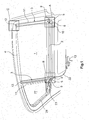
- the exemplary embodiments for a window roller blind illustrated in FIGS. 1 and 2 are suitable for covering a lateral vehicle window on the vehicle interior.
- the respective embodiment has a roller blind 1, which can be wound up and unwound on a roller shaft 2.
- the driving force is supplied for this purpose by a drive device 13, which may be preferably designed as an electric motor, in particular a DC motor.
- the drive device can be driven in two drive directions of rotation in order to drive the roller shaft 2 during winding and unwinding of the roller blind 1 in two opposite directions of rotation.
- roller blind 1 of the roller shaft 2 When unwinding the roller blind 1 of the roller shaft 2, this is rotated in the direction of the pull-out of the roller blind in the unwinding. The roller blind 1 is released for a pull-out.
- roller shaft 2 pulleys 5 are rotatably mounted relative to the roller shaft 2 and coaxial with the roller shaft 2.
- the storage takes place in the illustrated embodiments on rotatably connected to the roller shaft 2 drive shaft parts 9.
- These drive shaft parts 9 can be formed by a guided through the hollow roller shaft 2 one-piece drive shaft.
- the drive shaft is rotatably connected by their deviating from the circular cross-sectional shape shape with the roller shaft 2.
- longitudinally extending teeth or ribs on the circumference of the drive shaft or the drive shaft parts 9 may be provided at least in the region of the roller shaft 2.
- elongate tension members 11 which may be formed as cables, bands or the like, connected.
- the tension elements 11, 11 are formed so that they can be wound onto the pulleys 5 and unwound from the pulleys 5.
- the other ends of the tension elements 5 are, as will be explained in detail, with the two ends (right and left) in Figs. 1 and 2 of an extendable and preferably rigidly formed roller blind end 4, which may be formed as a pull-out rod in a known manner, connected.
- deflection rollers 12 which lie in the vicinity of the upper window boundary.
- the tension elements 11, the guide rollers 12 and the pulleys 5 form cables, which are provided at both ends of the roller shaft 2 and extend in the vertical direction along guide paths for the roller blind 1 during winding and unwinding.
- the axes of rotation of the pulleys 5 and the guide rollers 12 are arranged perpendicular to each other and in the embodiment of Fig. 2, the axes of the pulleys 5 and the guide rollers 12 are arranged parallel to each other.
- Fig. 6 the connection between the tension member 11 and the pull-out designed as a pull-out roller blind end 4 is shown in detail.
- the end of the tension member 11 is connected in an attachment point 21 with a carriage 19 which is guided in a carriage guide 20 substantially vertically along the movement path during winding and unwinding of the blind sheet 1.
- the extendable roller blind end 4 is preferably articulated and optionally resiliently connected. This arrangement is located on both sides of the extendable roller blind end 4.
- the springs 6 are supported on the rotating roller shaft 2 and exert the torques required for winding the tension elements 11 onto the pulleys 5.
- the springs 6 are formed as spiral or roller springs.
- Inner spring ends 7 are rotatably connected to the roller shaft 2. This can be done via the drive shaft parts 6, as shown in the illustrated embodiments.
- the inner spring ends 7 are firmly connected to the drive shaft parts 9.
- Outer spring ends 8 of the springs 6 are connected to the pulleys 5. This is done in the illustrated embodiments via spring housing 10, with which the pulleys 5 are rotatably connected.
- the springs 6 are arranged in the interior of the spring housing 10.
- roller shaft 2 When winding the roller blind 1 on the roller shaft 2, the roller shaft 2 is rotated by the drive device 13 in the opposite direction, i. Roller blind feed direction turned. In this case, a pull-in force is exerted on the blind sheet 1 in the winding direction via the roller shaft 2. This force is transmitted via the tension elements 11 on the pulleys 5 during unwinding of the tension elements 11 of the pulleys 5. Due to the speed difference between the roller shaft 2 and the pulleys 5, the springs 6 are tensioned. In this way, the springs 6 are brought into the desired state for a renewed roller blind extract.
- the drive device 13 can be brought into rotational drive connection with the roller shaft 2 in various ways. In the embodiment of FIG. 1, this is done by means of an elongate push / pull element 22, which as a brush cable, flexible toothed belt, flexible perforated belt or the like can be trained.
- the push / pull element 22 is flexible transversely to its direction of movement and rigid in the direction of movement.
- the longitudinal movement of the push / pull element 22 is converted by means of a gear 23, which may be formed as a bevel gear or worm gear, in a rotational movement of the drive shaft or the drive shaft parts 9 and thus the roller shaft 2.
- the roller shaft 2 can be moved during the winding and unwinding of the roller blind 1 in the direction of its shaft axis. By this axial displacement different widths of the roller blind during winding and unwinding can be compensated. Such axial displaceability is out DE 20 2004 000 631 U1 known.
- a vehicle-fixed spindle 16 is provided for the axial displaceability of the roller shaft, in the outer thread engages a rotationally fixed at the end of the roller shaft 2 arranged threaded engagement member 26.
- the threaded engagement piece 26 rotates together with the roller shaft 2. As a result, a controlled axial movement of the roller shaft 2 is achieved.
- a movable with the axial movement of the roller shaft 2 stop 18 may be provided on the roller blind end, which abuts against a stop fixed to the vehicle 18 to limit the extension length of the blind sheet 2. This extension length depends on the height of the vehicle window to be covered.
- the roller shaft 2 is returned to its original position.
- the right drive shaft part 9 extends through the vehicle-fixed spindle 16 and carries at the outer right end of the rotatably mounted pulley 5 with the associated spring 6, soft, as already explained, as a spiral or scroll spring in rotation with the pulley 5 connected spring housing 10 is arranged (Fig. 4).
- a stop 14 and the drive shaft part 9, a stop 15 are provided on the spring housing 10, a stop 14 and the drive shaft part 9, a stop 15 are provided.
- these two stops of the rotation angle range within which the spring housing 10th and the rotatably connected pulley 5 relative to the drive shaft part 9 and thus against the roller shaft 2 can rotate limited.
- the stops 14 and 15 of this rotation angle range is limited to a range of less than 360 °. In the illustrated embodiment, this rotation angle range is approximately 180 °. Other rotation angle ranges within> 0 ° and ⁇ 360 ° can also be selected.
- stops 14 and 15 ensures that occurring during the winding or unwinding of the roller blind along the guide lines movement resistance, for example, by tilting or foreign bodies acting on the roller shaft 2 drive force can be transmitted directly to the pulley 5.
- the drive movement of the push / pull element 22 can also be utilized for actuating a triangular window roller blind 27.
- the drive movement of the push / pull element 22 is transmitted to a pivotable pullout lever 28, as it is made DE 299 21 860 U1 is known.
Landscapes
- Engineering & Computer Science (AREA)
- Mechanical Engineering (AREA)
- Operating, Guiding And Securing Of Roll- Type Closing Members (AREA)
Applications Claiming Priority (1)
| Application Number | Priority Date | Filing Date | Title |
|---|---|---|---|
| DE200610028351 DE102006028351A1 (de) | 2006-06-20 | 2006-06-20 | Fensterrollo für ein Fahrzeugfenster |
Publications (2)
| Publication Number | Publication Date |
|---|---|
| EP1870271A1 true EP1870271A1 (fr) | 2007-12-26 |
| EP1870271B1 EP1870271B1 (fr) | 2012-01-18 |
Family
ID=38331405
Family Applications (1)
| Application Number | Title | Priority Date | Filing Date |
|---|---|---|---|
| EP20070011998 Ceased EP1870271B1 (fr) | 2006-06-20 | 2007-06-19 | Store pour une fenêtre de véhicule |
Country Status (2)
| Country | Link |
|---|---|
| EP (1) | EP1870271B1 (fr) |
| DE (1) | DE102006028351A1 (fr) |
Cited By (2)
| Publication number | Priority date | Publication date | Assignee | Title |
|---|---|---|---|---|
| EP3081415A1 (fr) * | 2015-04-14 | 2016-10-19 | BOS GmbH & Co. KG | Dispositif de protection pour un vehicule automobile |
| DE102016208676A1 (de) | 2016-05-19 | 2017-11-23 | Bos Gmbh & Co. Kg | Beschattungsvorrichtung für einen Fahrzeuginnenraum |
Families Citing this family (1)
| Publication number | Priority date | Publication date | Assignee | Title |
|---|---|---|---|---|
| DE202012000995U1 (de) | 2012-01-31 | 2012-04-24 | Lisa Dräxlmaier GmbH | Rollo mit Spannvorrichtung |
Citations (4)
| Publication number | Priority date | Publication date | Assignee | Title |
|---|---|---|---|---|
| EP1319772A1 (fr) * | 2001-12-14 | 2003-06-18 | MHZ SONNENSCHUTZTECHNIK GmbH | Store à rappel positif avec un dispositif de rattrapage de jeu unilatéral |
| DE202004000631U1 (de) | 2004-01-16 | 2004-03-18 | Hs Products Engineering Gmbh | Fahrzeugfensterrollo |
| EP1626152A1 (fr) * | 2004-08-09 | 2006-02-15 | BOS GmbH & Co. KG | Protection solaire pour un toit vitré |
| EP1645448A1 (fr) | 2004-10-08 | 2006-04-12 | HS Products Engineering GmbH | Store à rouleau de fenêtre pour vitres de véhicule |
-
2006
- 2006-06-20 DE DE200610028351 patent/DE102006028351A1/de not_active Withdrawn
-
2007
- 2007-06-19 EP EP20070011998 patent/EP1870271B1/fr not_active Ceased
Patent Citations (4)
| Publication number | Priority date | Publication date | Assignee | Title |
|---|---|---|---|---|
| EP1319772A1 (fr) * | 2001-12-14 | 2003-06-18 | MHZ SONNENSCHUTZTECHNIK GmbH | Store à rappel positif avec un dispositif de rattrapage de jeu unilatéral |
| DE202004000631U1 (de) | 2004-01-16 | 2004-03-18 | Hs Products Engineering Gmbh | Fahrzeugfensterrollo |
| EP1626152A1 (fr) * | 2004-08-09 | 2006-02-15 | BOS GmbH & Co. KG | Protection solaire pour un toit vitré |
| EP1645448A1 (fr) | 2004-10-08 | 2006-04-12 | HS Products Engineering GmbH | Store à rouleau de fenêtre pour vitres de véhicule |
Cited By (5)
| Publication number | Priority date | Publication date | Assignee | Title |
|---|---|---|---|---|
| EP3081415A1 (fr) * | 2015-04-14 | 2016-10-19 | BOS GmbH & Co. KG | Dispositif de protection pour un vehicule automobile |
| DE102015206661A1 (de) * | 2015-04-14 | 2016-10-20 | Bos Gmbh & Co. Kg | Schutzvorrichtung für ein Kraftfahrzeug |
| DE102015206661B4 (de) | 2015-04-14 | 2022-02-24 | Bos Gmbh & Co. Kg | Schutzvorrichtung für ein Kraftfahrzeug |
| DE102016208676A1 (de) | 2016-05-19 | 2017-11-23 | Bos Gmbh & Co. Kg | Beschattungsvorrichtung für einen Fahrzeuginnenraum |
| WO2017198376A1 (fr) | 2016-05-19 | 2017-11-23 | Bos Gmbh & Co. Kg | Système d'ombrage pour l'habitacle d'un véhicule |
Also Published As
| Publication number | Publication date |
|---|---|
| DE102006028351A1 (de) | 2007-12-27 |
| EP1870271B1 (fr) | 2012-01-18 |
Similar Documents
| Publication | Publication Date | Title |
|---|---|---|
| EP1905630B1 (fr) | Store de fenêtre actionné manuellement | |
| EP1645448B1 (fr) | Store à rouleau de fenêtre pour vitres de véhicule | |
| DE102013110650B4 (de) | Anordnung für ein Rollo | |
| EP1872989B1 (fr) | Store à enrouleur pour une fenêtre de véhicule | |
| DE19834777C2 (de) | Rollo, insbesondere Sonnenschutzrollo für die transparente Dachscheibe eines Kraftfahrzeugs | |
| EP3266631B1 (fr) | Dispositif d'ombrage pour une vitre de véhicule automobile | |
| DE102006046069A1 (de) | Fensterrollo mit reibungsmindertem Antrieb | |
| EP1771311A1 (fr) | Systeme de store | |
| EP1211113A2 (fr) | Dispositif d'entraínement pour toit coulissant de véhicule | |
| DE19539848C2 (de) | Rollo, insbesondere für Kraftfahrzeuge | |
| EP1870271B1 (fr) | Store pour une fenêtre de véhicule | |
| DE102008031467A1 (de) | Verstellvorrichtung für ein Verstellteil eines Kraftfahrzeugs und Verfahren zum Betrieb der Verstellvorrichtung | |
| DE102017218895B4 (de) | Schutzvorrichtung für einen Innenraum eines Kraftfahrzeugs | |
| DE10206161B4 (de) | Öffnungsfähiges Fahrzeugdach mit mindestens einem Deckel und zwei Abdeckeinrichtungen | |
| EP0529591B1 (fr) | Dispositif de store, de préference pour lunettes arrières de véhicules | |
| DE202006003901U1 (de) | Schiebetüranordnung für ein Kraftfahrzeug | |
| DE202004020106U1 (de) | Fensterrollo für ein Fahrzeugfenster | |
| EP1319772A1 (fr) | Store à rappel positif avec un dispositif de rattrapage de jeu unilatéral | |
| DE3700546C2 (fr) | ||
| DE202004019844U1 (de) | Fensterrollo für ein Fahrzeugfenster | |
| DE202006017838U1 (de) | Fensterrollo mit reibungsgemindertem Antrieb | |
| DE102010004432A1 (de) | Rollovorrichtung | |
| EP1878600B1 (fr) | Store pour une fenêtre latérale de véhicule | |
| DE102016001400A1 (de) | Rollo für einen Kraftwagen, insbesondere einen Personenkraftwagen | |
| DE202006017842U1 (de) | Rollo mit hinterschneidungsfreier Führungsschiene |
Legal Events
| Date | Code | Title | Description |
|---|---|---|---|
| PUAI | Public reference made under article 153(3) epc to a published international application that has entered the european phase |
Free format text: ORIGINAL CODE: 0009012 |
|
| AK | Designated contracting states |
Kind code of ref document: A1 Designated state(s): AT BE BG CH CY CZ DE DK EE ES FI FR GB GR HU IE IS IT LI LT LU LV MC MT NL PL PT RO SE SI SK TR |
|
| AX | Request for extension of the european patent |
Extension state: AL BA HR MK YU |
|
| RIN1 | Information on inventor provided before grant (corrected) |
Inventor name: ZIEGENBEIN, WERNER |
|
| 17P | Request for examination filed |
Effective date: 20080508 |
|
| AKX | Designation fees paid |
Designated state(s): DE FR GB IT |
|
| GRAP | Despatch of communication of intention to grant a patent |
Free format text: ORIGINAL CODE: EPIDOSNIGR1 |
|
| GRAS | Grant fee paid |
Free format text: ORIGINAL CODE: EPIDOSNIGR3 |
|
| GRAA | (expected) grant |
Free format text: ORIGINAL CODE: 0009210 |
|
| AK | Designated contracting states |
Kind code of ref document: B1 Designated state(s): DE FR GB IT |
|
| REG | Reference to a national code |
Ref country code: GB Ref legal event code: FG4D Free format text: NOT ENGLISH |
|
| REG | Reference to a national code |
Ref country code: DE Ref legal event code: R096 Ref document number: 502007009095 Country of ref document: DE Effective date: 20120322 |
|
| PLBE | No opposition filed within time limit |
Free format text: ORIGINAL CODE: 0009261 |
|
| STAA | Information on the status of an ep patent application or granted ep patent |
Free format text: STATUS: NO OPPOSITION FILED WITHIN TIME LIMIT |
|
| 26N | No opposition filed |
Effective date: 20121019 |
|
| REG | Reference to a national code |
Ref country code: DE Ref legal event code: R097 Ref document number: 502007009095 Country of ref document: DE Effective date: 20121019 |
|
| REG | Reference to a national code |
Ref country code: FR Ref legal event code: PLFP Year of fee payment: 10 |
|
| REG | Reference to a national code |
Ref country code: FR Ref legal event code: PLFP Year of fee payment: 11 |
|
| REG | Reference to a national code |
Ref country code: FR Ref legal event code: PLFP Year of fee payment: 12 |
|
| PGFP | Annual fee paid to national office [announced via postgrant information from national office to epo] |
Ref country code: IT Payment date: 20190619 Year of fee payment: 13 |
|
| PGFP | Annual fee paid to national office [announced via postgrant information from national office to epo] |
Ref country code: FR Payment date: 20190626 Year of fee payment: 13 |
|
| PGFP | Annual fee paid to national office [announced via postgrant information from national office to epo] |
Ref country code: GB Payment date: 20190624 Year of fee payment: 13 |
|
| GBPC | Gb: european patent ceased through non-payment of renewal fee |
Effective date: 20200619 |
|
| PG25 | Lapsed in a contracting state [announced via postgrant information from national office to epo] |
Ref country code: GB Free format text: LAPSE BECAUSE OF NON-PAYMENT OF DUE FEES Effective date: 20200619 Ref country code: FR Free format text: LAPSE BECAUSE OF NON-PAYMENT OF DUE FEES Effective date: 20200630 |
|
| PG25 | Lapsed in a contracting state [announced via postgrant information from national office to epo] |
Ref country code: IT Free format text: LAPSE BECAUSE OF NON-PAYMENT OF DUE FEES Effective date: 20200619 |
|
| REG | Reference to a national code |
Ref country code: DE Ref legal event code: R082 Ref document number: 502007009095 Country of ref document: DE Representative=s name: MATHYS & SQUIRE EUROPE PATENTANWAELTE PARTNERS, DE |
|
| PGFP | Annual fee paid to national office [announced via postgrant information from national office to epo] |
Ref country code: DE Payment date: 20240625 Year of fee payment: 18 |
|
| REG | Reference to a national code |
Ref country code: DE Ref legal event code: R119 Ref document number: 502007009095 Country of ref document: DE |
|
| PG25 | Lapsed in a contracting state [announced via postgrant information from national office to epo] |
Ref country code: DE Free format text: LAPSE BECAUSE OF NON-PAYMENT OF DUE FEES Effective date: 20260101 |