EP1211129A1 - Dossier pour siège de véhicule - Google Patents
Dossier pour siège de véhicule Download PDFInfo
- Publication number
- EP1211129A1 EP1211129A1 EP01309768A EP01309768A EP1211129A1 EP 1211129 A1 EP1211129 A1 EP 1211129A1 EP 01309768 A EP01309768 A EP 01309768A EP 01309768 A EP01309768 A EP 01309768A EP 1211129 A1 EP1211129 A1 EP 1211129A1
- Authority
- EP
- European Patent Office
- Prior art keywords
- support member
- seat back
- end portion
- lumbar
- frame
- Prior art date
- Legal status (The legal status is an assumption and is not a legal conclusion. Google has not performed a legal analysis and makes no representation as to the accuracy of the status listed.)
- Withdrawn
Links
- 230000000717 retained effect Effects 0.000 description 4
- 238000004804 winding Methods 0.000 description 4
- 229910000831 Steel Inorganic materials 0.000 description 2
- 238000005516 engineering process Methods 0.000 description 2
- 239000010959 steel Substances 0.000 description 2
- 229920005830 Polyurethane Foam Polymers 0.000 description 1
- 230000015556 catabolic process Effects 0.000 description 1
- 238000006243 chemical reaction Methods 0.000 description 1
- 238000006731 degradation reaction Methods 0.000 description 1
- 229920001971 elastomer Polymers 0.000 description 1
- 230000002708 enhancing effect Effects 0.000 description 1
- 239000004744 fabric Substances 0.000 description 1
- 230000002452 interceptive effect Effects 0.000 description 1
- 230000004048 modification Effects 0.000 description 1
- 238000012986 modification Methods 0.000 description 1
- 239000000088 plastic resin Substances 0.000 description 1
- 239000011496 polyurethane foam Substances 0.000 description 1
- 230000001681 protective effect Effects 0.000 description 1
- 239000005060 rubber Substances 0.000 description 1
- 238000003466 welding Methods 0.000 description 1
Images



Classifications
-
- B—PERFORMING OPERATIONS; TRANSPORTING
- B60—VEHICLES IN GENERAL
- B60N—SEATS SPECIALLY ADAPTED FOR VEHICLES; VEHICLE PASSENGER ACCOMMODATION NOT OTHERWISE PROVIDED FOR
- B60N2/00—Seats specially adapted for vehicles; Arrangement or mounting of seats in vehicles
- B60N2/64—Back-rests or cushions
- B60N2/66—Lumbar supports
- B60N2/667—Lumbar supports having flexible support member bowed by applied forces
- B60N2/6671—Lumbar supports having flexible support member bowed by applied forces with cable actuators
-
- B—PERFORMING OPERATIONS; TRANSPORTING
- B60—VEHICLES IN GENERAL
- B60N—SEATS SPECIALLY ADAPTED FOR VEHICLES; VEHICLE PASSENGER ACCOMMODATION NOT OTHERWISE PROVIDED FOR
- B60N2/00—Seats specially adapted for vehicles; Arrangement or mounting of seats in vehicles
- B60N2/64—Back-rests or cushions
- B60N2/66—Lumbar supports
- B60N2/667—Lumbar supports having flexible support member bowed by applied forces
-
- B—PERFORMING OPERATIONS; TRANSPORTING
- B60—VEHICLES IN GENERAL
- B60N—SEATS SPECIALLY ADAPTED FOR VEHICLES; VEHICLE PASSENGER ACCOMMODATION NOT OTHERWISE PROVIDED FOR
- B60N2/00—Seats specially adapted for vehicles; Arrangement or mounting of seats in vehicles
- B60N2/80—Head-rests
- B60N2/806—Head-rests movable or adjustable
- B60N2/838—Tiltable
-
- B—PERFORMING OPERATIONS; TRANSPORTING
- B60—VEHICLES IN GENERAL
- B60N—SEATS SPECIALLY ADAPTED FOR VEHICLES; VEHICLE PASSENGER ACCOMMODATION NOT OTHERWISE PROVIDED FOR
- B60N2/00—Seats specially adapted for vehicles; Arrangement or mounting of seats in vehicles
- B60N2/80—Head-rests
- B60N2/806—Head-rests movable or adjustable
- B60N2/865—Head-rests movable or adjustable providing a fore-and-aft movement with respect to the occupant's head
-
- B—PERFORMING OPERATIONS; TRANSPORTING
- B60—VEHICLES IN GENERAL
- B60N—SEATS SPECIALLY ADAPTED FOR VEHICLES; VEHICLE PASSENGER ACCOMMODATION NOT OTHERWISE PROVIDED FOR
- B60N2/00—Seats specially adapted for vehicles; Arrangement or mounting of seats in vehicles
- B60N2/80—Head-rests
- B60N2/888—Head-rests with arrangements for protecting against abnormal g-forces, e.g. by displacement of the head-rest
Definitions
- the present invention relates to a seat back assembly for a vehicle and, more particularly, to a vehicle seat back assembly which protects a neck of a seat occupant such as a cervical vertebra during a vehicle collision and to urge and support a lumbar of the seat occupant during a normal driving phase of the vehicle.
- the seat back assembly is constructed of a rectangular seat back frame, a support means supported with an upper end portion of the seat back frame for fore and aft tilting movement and for vertical movement, a head rest supported with an upper end portion of the support means by means of a head rest holder mounted to stays, and an actuation member supported with a lower end portion of the support means and moveable only in response to an impact force imposed by a back of an seat occupant.
- the seat back encounters an impact load applied in a forward direction to cause the seat occupant to rapidly move forward during a collision of the vehicle. Subsequently, the seat occupant undergoes a reaction force to rapidly move rearward, resulting in a reactive load imposed on the seat back assembly rearward. This is referred to as a secondary collision.
- a back element which extends between frame components of the seat back frame, and the actuation member are exerted with such an impact load.
- the head rest is instantaneously moved closer to the neck of the seat occupant.
- the neck of the seat occupant is reliably received with the head rest, enhancing a desired protection for the neck of the seat occupant.
- the specific feature of the seat back assembly only suffices a particular need for obtaining protection during the vehicle collision that would occur at infrequent timings.
- a specific structure is not pertinent for providing comfortable seat surroundings during a major part of the driving conditions of the vehicle. More particularly, because the lumbar support member, which serves to support the lumbar of the seat occupant in the major driving condition of the vehicle, should be located in a narrow spacing within the seat back frame, either one of or both of the lumbar support member and the actuation member are rendered to be too small in size with a resultant degradation in adequately comfortable support for the lumbar of the seat occupant. Another issue is encountered in that when the seat occupant leans back to the seat back in daily times, the load imposed by the seat occupant is transmitted to the associated parts to cause the head rest to move in an undesired direction.
- the present invention has been made with the above view and has an object to provide a vehicle seat back assembly which provides three satisfactions involving a first object for a neck of a seat occupant such as a cervical vertebra during a vehicle collision, a second object for supporting a lumbar of the seat occupant in a daily driving condition, and a third object for interrupting undesired movement of a head rest caused by daily leaning back movement of the seat occupant.
- a vehicle seat back assembly comprising: a seat back frame (2) having an upper frame component (2a) and a lower frame component (2c); a movable support member (7) supported with the upper frame component for tilting movement in forward and rearward directions relative to the seat back frame and vertical movement relative to the seat back frame; an actuation member (4) supported with a lower section of the movable support member and moveable rearward in response to impact force exerted by a seat occupant relatively to the seat back frame; a first support member (5) coupled to the lower frame component of the seat back frame; a second support member (6) coupled to the movable support member; a head rest (3) supported with an upper section of the movable support member; and a lumbar support member (8) having an upper end portion coupled to the second support member and a lower end portion coupled to the first support member to take on a position to resiliently support a lumbar of the seat occupant.
- the first support member and the second support member support the upper end portion and the lower end portion of the lumbar support member to allow the upper end portion and the lower end portion of the lumbar support member to be tilted in forward and rearward directions relatively to the seat back frame and vertically moved relatively to the seat back frame.
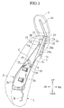
- the vehicle seat back assembly 1 is constructed of a seat back frame 2 made of steel plate and composed of a pair of side frame components 2b, 2b' which are laterally spaced from one another and substantially stand upright, an upper frame component 2a connected to upper distal ends of the side frame components 2b, 2b'and a lower frame component 2c connected to lower distal ends of the side frame components 2b, 2b'.
- the vehicle seat back assembly 1 is also constructed of a movable support member 7 composed of a pair of armature pipes 7A, 7A which are supported with the upper frame component 2a for fore and aft tilting movement and for upward and downward movement, a head rest 3 supported with upper end portions 7a, 7a of the armature pipes 7A, 7A, respectively, an actuation member 4 supported with lower end portions 7b, 7b of the armature pipes 7A, 7A and moveable only upon receipt of impact force exerted from a back of a seat occupant which is not shown, a lumbar support member 8 supported with the seat back frame 2 and the movable support member 7 through the actuation member 4, a pad (not shown) which is formed by use of polyurethane foam and is covered over front and rear facing surfaces of the seat back frame 2, and a decorative fabric skin layer (not shown) covered over the pad.
- a movable support member 7 composed of a pair of armature pipes 7A, 7A which are supported with the upper
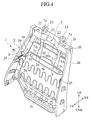
- the lumbar support member 8 is made of a unitary structure which includes a lower end portion 9, which is formed with cutouts 9a with which the first support member 5 engages to allow the lower end portion 9 to tilt forward FR and rearward RR, an upper end portion 10 which is formed with cutouts 10a with which the second support member 6 engages to allow the upper end portion 10 to tilt forward FR and rearward RR and to move upward UP and downward LWR, and a body section 11 which is movable forward FR so as to protrude for resiliently supporting a lumbar of the seat occupant (not shown).
- the body section 11 includes a pair of first laterally spaced, vertically elongated flat members 11a, 11a and a plurality of second vertically spaced rib members 11b which laterally extend outward from the first flat members 11a, 11a at six positions, respectively.
- each of the first flat members 11a, 11a has at its rear side a leaf-spring shaped, first urging member 12 which urges the body section 11 in a direction to restore in a substantially flat state from the protruding position of the body section 11.
- a center wire 13 is located at a rear side of the lumbar support member 8 and has a lower end 13a engaging the lower end portion 9a of the lumbar support member 8 and an upper end 13b fixedly secured to a central portion of a laterally extending yoke bar 14 to allow its rocking movement.
- One distal end 14a of the yoke bar 14 is connected to the upper end portion 10 of the lumbar support member 8 by means of a coil-spring shaped, second urging member 15 such that the one distal end 14a is urged upward UP at all times. That is, the second urging member 15 remains in a contracting state at all times.
- yoke bar 14 is interconnected with an inner cable 17a of a cable 17 extending from an operation unit 16 such that actuation of the operation unit 16 enables the body section 11 of the lumbar support member 8 to move frontward FR against the forces of the first and second urging members 12, 15.
- Reference numeral 15a refers to a sleeve shaped cover which conceals the second urging member 15.
- the operation unit 16 includes a retractor 18 fixedly mounted to the side frame component 2' of the seat back frame 2 for winding the inner cable 17a of the cable 17, and a manually operated actuation lever 19 for actuating the retractor 18 either in a winding direction or in a winding-release direction.
- Operating the actuation lever 19 in the winding direction causes the retractor 18 to wind the inner cable 17a of the cable 17 to thereby lift up the other end 14b of the yoke member 14.
- the yoke bar 14 rotates substantially about the one end 14a of the yoke bar 14 as a rotational center to allow the center wire 13 to be lifted up.
- the yoke bar 14 is moved to its extreme stop position where the inner cable 17a is fully wound up in the retractor 18 and can be stopped in a position corresponding to the extreme stop position of the inner cable 17a, the yoke bar 14 per se has various angularly adjusted positions maintained in a balanced state between an expanding and contracting conditions of the second urging member 15.
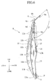
- the second support member 6 includes a pair of retainer segments 6a, 6a which are retained with the intermediate portions 7c, 7c of the armature pipes 7, 7, respectively, a pair of slanted segments 6b, 6b extending downward from respective inner distal ends of the retainer segments 6a, 6a in a spaced relationship with respect to one another, a pair of lower vertical segments 6d, 6d extending downward from respective lower distal ends 6c, 6c of the slanted segments 6b, 6b for vertical sliding movement with respect to the lumbar support member 8, and a laterally extending stopper segment 6e integrally formed with respective distal ends of the vertical segments 6d, 6d for precluding the upper end portion 10 from being separated from the lumbar support member 8.
- each of the slanted segments 6b, 6b is oriented at an angle ⁇ of 134.6 degrees relative to the vertical segment 6d.
- each of the vertical segments 6d, 6d is vertically spaced from the retainer segment 6a at which the second support member 6 is retained.
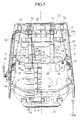
- the seat back frame 2 includes the upper frame component 2a which is located at an upper extreme end and extends in a substantially transverse direction, the pair of laterally spaced, elongated upright side frame components 2b, 2b' extending at both ends of the upper frame component 2a, and the lower frame component 2c extending between the lower distal ends of the side frame components 2b, 2b' in the substantially transverse direction, with all the frame components being mutually welded together to provide a rigid structure.
- the upper frame component 2a has a downwardly extending rear wall 2aa which retains stopper rubbers 32 that are held in resilient contact with the armature pipes 7A, 7A, respectively.
- a retaining plate 20 is constructed at a front side FR of the upper frame component 2a, with a substantially hollow, channel shaped cross section, which is welded to the upper frame component 2a and the rear wall 2aa.
- the retaining plate 20 has a lower wall whose rear end has a downwardly extending rear wall segment 20a which is secured to a lower end of the rear wall 2aa of the upper frame component 2a to allow armature holders 21, 21 to be fixedly secured to the rear wall segment 20a at a position below the lower wall of the retaining plate 20 by welding.
- the armature holders 21, 21 support the armature pipes 7A, 7A for tilting movement and vertical movement, respectively. As viewed in FIGS.
- the upper frame components 2a has laterally spaced elongated slots 22, 22 elongated in a fore and aft direction and formed at the upper and lower walls in vertically aligned relationships.
- Head rest holders 23, 23 are made of plastic resin and fitted to the respective upper distal ends 7a, 7a of the armature pipes 7A, 7A, respectively, to allow stays 24, 24 of a head rest 3 to be received in vertical movement to be fixedly retained at a suitable position.
- the actuation member 4 is formed in a laterally extending elongated rigid structure made of steel plate and has an upper end formed with an inclined section 28 extending between the armature pipes 7A, 7A and oriented rearward RR. Further, both ends of the actuation member 4 have forwardly bent flanges 4a, 4a, which are pivotally connected to one distal ends of actuating links 29, 29 by means of bolts 30, 30, respectively. Other distal ends of the actuating links 29, 29 are pivotally supported with the side frame components 2b, 2b' by means of bolts P, P, respectively.
- a pair of coil springs 25, 25 have one ends hooked to respective forward ends of the side frame components 2b, 2b' and the other ends connected to respective intermediate portions of the actuating links 29, 29 to urge the actuation member 4 in the forward direction FR at all times.
- the coil springs 25, 25 serve as a third urging member.
- a fourth urging member is composed of a pair of laterally located S-shaped springs 26, 26 which are suspended between the side frame components 2b, 2b' in a vertically spaced relationship.
- a C-shaped stopper wire 27 has upright ends fixedly secured to a lower end portion of the rear wall segment 20a of the retaining plate 20 to prevent excessive rotating movements of the armature pipes 7A, 7A.
- the armature pipes 7A, 7A stand upright in a laterally spaced relationship and are supported at least inside a shoulder points of AF05 percentile mannequin (SAE). Supporting the armature pipes 7A, 7A inside the shoulder points of AF05 percentile mannequin (SAE) renders the armature pipes 7A, 7A to be located inside the shoulder points of physical constitutions of most of adults.
- SAE AF05 percentile mannequin
- each armature pipe 7A is slightly bent.
- the bent portions 7c are shaped at points where they do not interfere with lower end portions 24a, 24a of the stays 24, 24, with an internal surface of each bent portion 7c having a curved surface with a radius of 20 mm.
- the lumbar support member 8 is supported with the armature pipes 7A, 7A via the second support member 6 and the slanted segments 6b, 6b of the second support member 6 remain in a flexible state, applying load to the lumbar support member 8 allows the slanted segments 6b, 6b of the second support member 6 to be deflected to preclude the movements of the armature pipes 7A, 7A. When this takes place, the head rest 3 remains unchanged in the fore and aft direction.
- first and second support members 5 and 6 made of wires, respectively, enables the first and second support members 5 and 6 for smooth rotations or movements, respectively, so as to allow the lumbar support member 8 to be deformed, even when the lumbar support member 8 is deformed to protrude or is caused to restore its original substantially flat position.
- the lumbar support member 8 is supported with the vertical segments 6d, 6d of the second support member 6 at the position separated from the retainer segments 6a, 6a, the load imposed by the seat occupant leaning back in the seat back assembly 1 causes the slanted segments 6b, 6b of the second support member 6 to be flexed to preclude the load from being imposed on the armature pipes 7A, 7A, thereby maintaining the head rest 3 in its original condition. Under the same situation, further, the lumbar of the seat occupant is retainable with the lumbar support member 8.
- the second support member 6 constructed of the retainer segments 6a, 6a which provide the support positions for the armature pipes 7A, 7A
- the slanted segments 6b, 6b which extend from the retainer segments 6a, 6a obliquely downward and vertical segments 6d, 6d which vertically extend downward from the slanted segments 6b, 6b enabling vertical sliding movement for the lumbar support member 8
- the load imposed by the seat occupant leaning back in the seat back assembly 1 causes the slanted segments 6b, 6b of the second support member 6 to be flexed to prevent the load from being imposed on the armature pipes 7A, 7A for retaining the head rest 3 in its initial position.
- the armature pipes 7A, 7A are enabled to move in a smooth manner. In other words, there are no limits for the movement of the armature pipes 7A, 7A.
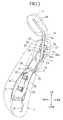
- the actuating links 29, 29 rotate upward UP and rearward RR
- the lower end portions 7b, 7b of the armature pipes 7A, 7A i.e., the actuation member 4 is moved upward UP and rearward RR.
- the upper end portions 7a, 7a of the armature pipes 7A, 7A and the head rest holders 23, 23 are moved upward UP and forward FR. Due to upward movements of the head rest holders 23, 23, the stays 24, 24 of the head rest 3 are also moved upward UP and forward FR.
- both the armature pipes 7A, 7A and the stays 24, 24 move about the centers of the armature holders 21, 21, the head rest 3 supported with the stays 24, 24 is brought into abutting contact with the head of the seat occupant to support the head of the seat occupant in place.
- the inclined section 28 formed in an upper area of the actuation member 4 and oriented rearward RR is enabled to move along the rear surface of the pad. In other words, it is difficult for the actuation member 4 to be squeezed into the pad.
- the head rest 3 since the stays 24, 24 of the head rest 3 are supported with the head rest holders 23, 23 for vertical sliding movements, it is possible for the head rest 3 to be suitably matched to various heights of the heads of the seat occupants with different physical constitutions.
- the lumbar support member 8 which includes the body section 11, which is capable of protruding forward so as to resiliently support the lumbar of the seat occupant and which is formed in the unitary structure with the lower end portion 9 with which the first supporting member 5 engages and the upper end portion 10 with which the second supporting member 6 engages, and the first urging member 12 for urging the body section 11 in the direction to restore its original position from its protruded position.
- the yoke bar 14 is connected to the lower end portion 9 of the lumbar support member 8 for tilting movement.
- the yoke bar 14 has the one distal end 14a which is urged upward UP at all times by the action of the second urging member 15, and the other distal end 14b which is connected to the operation unit 16 such that operation of the operation unit 16 allows the body section 11 of the lumbar support member 8 to protrude forward FR against the forces of the first and second urging members 12, 15.
- actuating the operation unit 16 in the direction to cause forward protruding movement of the body section 11 enables the forward movement of the body section 11 in an adjusted position to suitably support the lumbar of the seat occupant against the forces of the first and second urging members 12, 15.
- actuating the operation unit 16 in another direction to interrupt the forward movement of the body section 11 enables the body section 11 to move to the position not to support the lumbar of the seat occupant by the actions of the first and second urging members 12, 15.
Landscapes
- Engineering & Computer Science (AREA)
- Aviation & Aerospace Engineering (AREA)
- Transportation (AREA)
- Mechanical Engineering (AREA)
- Seats For Vehicles (AREA)
- Chair Legs, Seat Parts, And Backrests (AREA)
Applications Claiming Priority (2)
| Application Number | Priority Date | Filing Date | Title |
|---|---|---|---|
| JP2000359066A JP2002160567A (ja) | 2000-11-27 | 2000-11-27 | 自動車用シートバック |
| JP2000359066 | 2000-11-27 |
Publications (1)
| Publication Number | Publication Date |
|---|---|
| EP1211129A1 true EP1211129A1 (fr) | 2002-06-05 |
Family
ID=18830890
Family Applications (1)
| Application Number | Title | Priority Date | Filing Date |
|---|---|---|---|
| EP01309768A Withdrawn EP1211129A1 (fr) | 2000-11-27 | 2001-11-20 | Dossier pour siège de véhicule |
Country Status (2)
| Country | Link |
|---|---|
| EP (1) | EP1211129A1 (fr) |
| JP (1) | JP2002160567A (fr) |
Cited By (5)
| Publication number | Priority date | Publication date | Assignee | Title |
|---|---|---|---|---|
| EP1134115A3 (fr) * | 2000-03-14 | 2003-03-26 | Ikeda Bussan Co., Ltd. | Structure de dossier de véhicule |
| WO2006081865A1 (fr) * | 2005-02-02 | 2006-08-10 | Schukra Gerätebau AG | Element de soutien dorsolombaire et son procede de production |
| GB2426925A (en) * | 2005-06-07 | 2006-12-13 | Lear Corp | Vehicle seat upper back frame structure |
| DE102007013341A1 (de) * | 2007-03-02 | 2008-09-04 | L & P Swiss Holding Company | Befestigungsvorrichtung und Verfahren zum Anbringen einer Lordosenstützvorrichtung an einem Sitzrahmen sowie entsprechende Lordosenstützvorrichtung |
| CN101445071B (zh) * | 2007-11-27 | 2012-10-10 | 现代自动车株式会社 | 车辆用活动头靠装置 |
Families Citing this family (1)
| Publication number | Priority date | Publication date | Assignee | Title |
|---|---|---|---|---|
| JP4445346B2 (ja) * | 2004-08-19 | 2010-04-07 | 日本発條株式会社 | 車両用シート |
Citations (4)
| Publication number | Priority date | Publication date | Assignee | Title |
|---|---|---|---|---|
| WO1998009838A1 (fr) * | 1996-09-06 | 1998-03-12 | Saab Automobile Ab | Siege de vehicule pourvu d'un appui-tete |
| US5984407A (en) * | 1996-02-23 | 1999-11-16 | Mccord Winn Textron Inc. | Cable attachment for a lumbar support |
| EP0967115A2 (fr) * | 1998-06-26 | 1999-12-29 | Volkswagen Aktiengesellschaft | Siège de véhicule à appui-tête |
| EP1134115A2 (fr) * | 2000-03-14 | 2001-09-19 | Ikeda Bussan Co., Ltd. | Structure de dossier de véhicule |
-
2000
- 2000-11-27 JP JP2000359066A patent/JP2002160567A/ja active Pending
-
2001
- 2001-11-20 EP EP01309768A patent/EP1211129A1/fr not_active Withdrawn
Patent Citations (4)
| Publication number | Priority date | Publication date | Assignee | Title |
|---|---|---|---|---|
| US5984407A (en) * | 1996-02-23 | 1999-11-16 | Mccord Winn Textron Inc. | Cable attachment for a lumbar support |
| WO1998009838A1 (fr) * | 1996-09-06 | 1998-03-12 | Saab Automobile Ab | Siege de vehicule pourvu d'un appui-tete |
| EP0967115A2 (fr) * | 1998-06-26 | 1999-12-29 | Volkswagen Aktiengesellschaft | Siège de véhicule à appui-tête |
| EP1134115A2 (fr) * | 2000-03-14 | 2001-09-19 | Ikeda Bussan Co., Ltd. | Structure de dossier de véhicule |
Cited By (7)
| Publication number | Priority date | Publication date | Assignee | Title |
|---|---|---|---|---|
| EP1134115A3 (fr) * | 2000-03-14 | 2003-03-26 | Ikeda Bussan Co., Ltd. | Structure de dossier de véhicule |
| WO2006081865A1 (fr) * | 2005-02-02 | 2006-08-10 | Schukra Gerätebau AG | Element de soutien dorsolombaire et son procede de production |
| GB2426925A (en) * | 2005-06-07 | 2006-12-13 | Lear Corp | Vehicle seat upper back frame structure |
| GB2426925B (en) * | 2005-06-07 | 2007-10-10 | Lear Corp | Method of assembling a portion of a vehicle seat frame structure |
| US7581792B2 (en) | 2005-06-07 | 2009-09-01 | Lear Corporation | Vehicle seat frame structure and method of assembling a portion of a vehicle seat frame |
| DE102007013341A1 (de) * | 2007-03-02 | 2008-09-04 | L & P Swiss Holding Company | Befestigungsvorrichtung und Verfahren zum Anbringen einer Lordosenstützvorrichtung an einem Sitzrahmen sowie entsprechende Lordosenstützvorrichtung |
| CN101445071B (zh) * | 2007-11-27 | 2012-10-10 | 现代自动车株式会社 | 车辆用活动头靠装置 |
Also Published As
| Publication number | Publication date |
|---|---|
| JP2002160567A (ja) | 2002-06-04 |
Similar Documents
| Publication | Publication Date | Title |
|---|---|---|
| EP1203692B1 (fr) | Ensemble chassis pour dossier de siège de véhicule | |
| JP4737501B2 (ja) | 車両用シート | |
| JP2001253282A (ja) | 自動車用シートバック | |
| WO2008004678A1 (fr) | Siège de véhicule | |
| JP2000517269A (ja) | ヘッドレストを備えた車両の座席 | |
| JP3783225B2 (ja) | 車両用シート構造 | |
| JP2003341401A (ja) | 自動車用シートバック | |
| US6840560B2 (en) | Vehicular seat assembly having a movable headrest and a vehicle which incorporates the vehicular seat assembly | |
| JP2000211412A (ja) | 自動車用シ―トバック | |
| JP2000201769A (ja) | 自動車用シ―トバック | |
| JP2000201770A (ja) | 自動車用シ―トバック | |
| JP4640969B2 (ja) | 車両用シートおよび車両用シートの組立方法 | |
| JP2002160567A (ja) | 自動車用シートバック | |
| JP2000175761A (ja) | 車両用シートクッション | |
| JP2002345597A (ja) | 乗り物用シート | |
| JP2005131047A (ja) | 背凭れ傾動装置 | |
| JP4450316B2 (ja) | 車両用シート | |
| KR100494550B1 (ko) | 자동차용 럼버서포트 장치 연동형 등판 지지구조 | |
| JP2000210157A (ja) | 自動車用シ―トバック | |
| JP2001058533A (ja) | 自動車用シートバック | |
| JP3522548B2 (ja) | 自動車用シートバック | |
| JP2001039194A (ja) | 自動車用シートバック | |
| JP3563685B2 (ja) | 自動車用シートバック | |
| JP3595767B2 (ja) | 自動車用シートバック | |
| JP2000052830A (ja) | 車両用シートバック |
Legal Events
| Date | Code | Title | Description |
|---|---|---|---|
| PUAI | Public reference made under article 153(3) epc to a published international application that has entered the european phase |
Free format text: ORIGINAL CODE: 0009012 |
|
| 17P | Request for examination filed |
Effective date: 20011203 |
|
| AK | Designated contracting states |
Kind code of ref document: A1 Designated state(s): AT BE CH CY DE DK ES FI FR GB GR IE IT LI LU MC NL PT SE TR |
|
| AX | Request for extension of the european patent |
Free format text: AL;LT;LV;MK;RO;SI |
|
| AKX | Designation fees paid |
Designated state(s): AT BE CH CY DE DK ES FI FR GB GR IE IT LI LU MC NL PT SE TR |
|
| 17Q | First examination report despatched |
Effective date: 20040618 |
|
| STAA | Information on the status of an ep patent application or granted ep patent |
Free format text: STATUS: THE APPLICATION IS DEEMED TO BE WITHDRAWN |
|
| 18D | Application deemed to be withdrawn |
Effective date: 20041029 |