EP1211343A2 - Fadenrolleneinrichtung für eine Tuftingmaschine - Google Patents
Fadenrolleneinrichtung für eine Tuftingmaschine Download PDFInfo
- Publication number
- EP1211343A2 EP1211343A2 EP01309863A EP01309863A EP1211343A2 EP 1211343 A2 EP1211343 A2 EP 1211343A2 EP 01309863 A EP01309863 A EP 01309863A EP 01309863 A EP01309863 A EP 01309863A EP 1211343 A2 EP1211343 A2 EP 1211343A2
- Authority
- EP
- European Patent Office
- Prior art keywords
- yarn
- yarn feed
- drive
- drive roller
- roller
- Prior art date
- Legal status (The legal status is an assumption and is not a legal conclusion. Google has not performed a legal analysis and makes no representation as to the accuracy of the status listed.)
- Granted
Links
Images



Classifications
-
- D—TEXTILES; PAPER
- D05—SEWING; EMBROIDERING; TUFTING
- D05C—EMBROIDERING; TUFTING
- D05C15/00—Making pile fabrics or articles having similar surface features by inserting loops into a base material
- D05C15/04—Tufting
- D05C15/08—Tufting machines
- D05C15/16—Arrangements or devices for manipulating threads
- D05C15/18—Thread feeding or tensioning arrangements
-
- D—TEXTILES; PAPER
- D05—SEWING; EMBROIDERING; TUFTING
- D05C—EMBROIDERING; TUFTING
- D05C15/00—Making pile fabrics or articles having similar surface features by inserting loops into a base material
- D05C15/04—Tufting
- D05C15/08—Tufting machines
- D05C15/26—Tufting machines with provision for producing patterns
- D05C15/32—Tufting machines with provision for producing patterns by altering the loop length
Definitions
- the present invention relates to a yarn feed roller assembly for a tufting machine, and also to a method of controlling the pile height of individual stitches in a tufting machine.
- U.S. 5,182,997 discloses a yarn feed roller assembly with two longitudinally extending drive rollers, each of which is rotated at a different speed. Associated with each end of yarn is a pivotal arm having a pair of yarn feed wheels each associated with a respective drive roller. A control mechanism is arranged to move the pivotal arm to bring one or other of the feed wheels into contact with a corresponding drive roller so that the yarn is driven by one or other of the drive rollers. When the faster drive roller is used, the yarn feed speed is high thereby tufting a high pile. On the other hand, when the low speed roller is used, the yarn feed speed is reduced and a low pile is tufted. The machine allows the pile height of each individual stitch to be controlled to be either high or low. This individual control is known as a full repeat scroll.
- a machine referred to as a three pile height full repeat scroll has been developed by the applicant.
- this machine uses three drive rollers each of which is driven at a different speed.
- three different pile heights can be formed.
- a yarn feed roller assembly for a tufting machine comprises a first drive roller arranged to be rotatably driven, and a plurality of actuators, each being arranged to bring an end of yarn selectively into driving engagement with the first drive roller; characterised by control means containing pattern data relating to the required pile height of each stitch, the control means being arranged to calculate from this the required proportion of the stroke for which the yarn is required to be driven by the first drive roller to achieve the required pile height, and to control the movement of each actuator so that an end of yarn is driven by the first drive roller for the required proportion of the needle stroke.
- This machine provides the same patterning capabilities of continuously variable pile heights that are obtainable with the machine which has a servo motor for each end of yarn.
- a machine according to the present invention can be produced for significantly less than the cost of the machine with servo motors.
- the yarn is driven only by the first drive roller and is engaged with this roller for as long as is necessary to generate the required pile height.
- the yarn has to be gripped when it is not being driven by the drive roller to prevent the yarn from being dragged into the backing cloth by the needles.
- a preferred option is to provide a second drive roller which is arranged to rotate at a slower speed than the first drive roller, wherein each actuator is arranged to switch an end of yarn such that it is driven either by the first or the second roller to obtain the required pile height.
- the actuator in order to produce higher pile heights, the actuator will leave the yarn in contact with the first drive roller for a longer proportion of the needle stroke, while to produce lower pile heights, the actuator will leave the yarn in contact with the second drive roller for a longer period.
- the twin roller arrangement allows the yarn to be fed constantly during the needle stroke, rather than the stop/start motion provided by the single drive roller arrangement. This allows full control of the yarn during the whole needle stroke.
- the invention could be performed with a yarn feed roller assembly having three or more drive rollers all driven at different speeds.
- the presence of more than two rollers does not allow a greater variety of pile heights to be generated. However, it will have some benefit in that it can reduce the frequency with which the actuator switches between rollers.
- a yarn feed roller assembly with three drive rollers will be able to produce three different pile heights without having to switch from one roller to another during a needle stroke, it may be that the majority of the carpet can be produced using these three pile heights. Nevertheless, when required, the actuators can switch the yarn from one roller to another during the needle stroke hence producing stitches with intermediate heights.
- Each actuator may comprise a pivotable arm having a pair of yarn feed wheels one of which is arranged to selectively press the yarn into engagement with the first drive roller, and the other of which is arranged to selectively press the yarn into engagement with the second drive roller as the arm is pivotally moved.
- the actuator is provided by an arm having a yarn feed wheel about which the yarn is engaged, and an intermediate wheel which drivingly engages with the yarn feed wheel, the arm being movable such that the intermediate wheel can be selectively brought into driving engagement with either of the first and second drive rollers.
- the actuator is provided by an arm having a yarn feed wheel, the arm being moveable such that the yarn feed wheel can be selectively brought into driving engagement either with the first or second drive rollers, and means for guiding the yarn around a portion of the yarn feed wheel which does not contact the drive rollers, the yarn feed wheel having a surface which engages with the yarn so as to provide a frictional drive for the yarn.
- a plurality of actuators are arranged in a stacked configuration in which adjacent actuators share a common first or second drive roller. This provides a compact arrangement with allows finer pitches to be achieved.
- the present invention also extends to a method of controlling the pile height of individual stitches in a tufting machine comprising, a drive roller arranged to be rotatably driven and a plurality of actuators each being arranged to bring an end of yarn selectively into contact with the drive roller, the method comprising the steps of:
- the tufting machine to which the present invention is applicable has a conventional construction. Thus, a detailed explanation of the workings of the machine will not be provided here.
- the tufting machine as shown in Figure 1 has a pair of needle bars 1 to each of which a plurality of needle modules 2 are attached. Each module 2 has a plurality of needles 3. Conventional reciprocating mechanisms 4 are provided to reciprocate both sets of needles.
- Each needle bar 1 is fed with the yarn Y from its own separate yarn feed arrangement.
- Figure 1 only the yarn feed arrangement for the left hand needle bar 1 is shown, although it should be appreciated that there is a second identical yarn feed assembly for the right hand needle bar 1.
- Yarn is fed from a creel (not shown) into the yarn feed roller assembly.
- Yarn for the adjacent needle 3 to that shown in Figure 1 follows a slightly different path as indicated at Y' in Figure 1 as is known in the art.
- the yarn feed roller assembly comprises a first drive roller 5 positioned directly above a second drive roller 6.
- the drive rollers extend longitudinally of the machine and will generally extend the full width of the machine, although two or more drive rollers may be provided end to end to span the full width of the machine.
- the first drive roller 5 is driven by a belt 7 while the second drive roller 6 is driven by a belt 8 in a known manner.
- the drive rollers 5, 6 may alternatively be directly driven.
- the first 5 and second 6 drive rollers are arranged to be driven at different speeds. It is unimportant with this arrangement which is the faster of the two drive rollers.
- the mechanism for switching the yarn between the first 5 and second 6 drive roller comprises an arm 9 which is shown in chain lines in Figure 1, which is pivotally mounted to the machine housing about a fulcrum 10 towards its centre.
- One such arm is provided for each end of yarn to feed the yarn to an individual needle.
- the arm 9 as shown in Figure 1 is in a position in which its left hand end is in its uppermost position and the right hand end is in the lowermost position.
- the arm 9 is biased into this position by a spring 11 which is at its minimum length.
- the arm is movable into its second position by means of a pneumatic actuator 12 which contacts a contact surface 13 to force the right hand end of the arm 9 upwardly against the action of the spring 11.
- the pneumatic actuator can be replaced by an alternative device and may be, for example, piezo electric, electromagnetic or hydraulic.
- a yarn feed wheel 14 is provided at the left hand extremity of the arm 9.
- An intermediate wheel 15 positioned between the drive rollers 5, 6 and in close engagement with the yarn feed wheel 14.
- the outer surfaces of the yarn feed wheel 14 and intermediate wheel 15 are made of polyurethane rubber.
- Yarn feed wheel 14 is spring loaded so that it can be moved away from the intermediate wheel 15 to allow the yarn Y to be threaded round the yarn feed wheel 14.
- the yarn feed wheel is then returned to its operating position to nip the yarn between the yarn feed wheel 14 and intermediate wheel 15.
- the yarn is driven upon the rotation of these two wheels.
- the left hand end of the arm 9 is in its uppermost position, in which the intermediate wheel 15 engages with the first drive roller 5, such that the yarn Y is driven at a speed determined by the first drive roller 5.
- the pneumatic actuator 12 is actuated, the left hand end of the arm 9 is moved downwardly bringing the intermediate wheel 15 into engagement with the lower drive roller 6, hence driving the yarn Y at a speed determined by the second drive roller 6.
- the yarn Y Upon leaving the yarn feed roller assembly, the yarn Y is fed through a pair of gear-type puller rolls 16 which brush against the yarn, rather than driving it, and serve to maintain the tension in the yarn while isolating the yarn feed assembly from variations in the yarn tension caused by a reciprocation of the needles 3. The yarn then extends through a pair of guide plates 17, 18 and then to the needles 3.
- the tufting machine is provided with pattern data which contains information on the required height of each stitch of the pattern.
- a control means receives this data and controls the timing of actuation of the pneumatic actuator 12 accordingly.
- the roller 5 is the high speed roller
- the roller 6 is the low speed roller
- the arm 9 In order to tuft a carpet at the full pile height as shown in Figure 2(A), the arm 9 is in engagement with the high speed roller 5 at the start of the needle stroke and remains in engagement with this roller throughout the stroke. Thus, at all times, the yarn is being fed at the fastest rate and therefore tufts at the maximum pile height (in this case 20.0mm).
- FIG. 2(F) a carpet tufted at the lowest possible pile height is shown in Figure 2(F).
- the arm 9 is in contact with the low speed roller 6 at the start of the needle stroke and throughout the stroke.
- the yarn Y is fed at the lowest rate hence, tufting at the lowest possible pile height (in this case, 4.0mm).
- Figures 2(B), to 2(E) show four intermediate stages between these two extremes. The height of the pile is determined by the point during the needle stroke when the yarn switches from being driven by one of the drive rollers to the other.
- the control means operates to maintain the intermediate roller 9 in contact with the high speed roller 5 for 80% of the needle stroke, and switches for 20% of the needle stroke to the low speed roller 6.
- the intermediate roller 15 is moved between the high speed 5 and low speed 6 rollers. Optimum performance is achieved if this movement is done only once per needle stroke. However, there is no reason why this should not be done any greater number of times.
- the control could be set such that the intermediate wheel 15 is moved into a default position in contact with one or other of the rollers 5, 6 at the beginning of each stroke. However, it is preferable for a stroke of each needle to begin with the intermediate wheel 15 in the position that it was in at the end of the previous needle stroke. In particular, if the pattern data requires a number of stitches at either the maximum or the minimum pile height, there is no need to move the intermediate wheel 15 at all while these stitches are being formed.
- the time during which the intermediate wheel is out of contact with either wheel during the switching process is minimal (less than 1 millisecond).
- the effects of this are negligible, particularly given that the yarn is always nipped between the yarn feed wheel 14 and intermediate wheel 15 so that the yarn cannot slide at this time, and given the inertia of the system.
- the pneumatic actuators take a finite time (typically 10 milliseconds) to react, but as this time is predictable, the control system can be set up to allow for this.
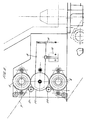
- FIG 3 An alternative actuator mechanism for switching between the two drive rollers 5, 6 is shown in Figure 3.
- most of the assembly is as shown in Figure 1 including the drive rollers 5, 6 and the spring 11 and pneumatic actuator 12.
- the yarn feed wheel 14 and intermediate wheel 15 have been replaced by a single yarn feed wheel 20 and upper 21 and lower 22 fixed yarn guide bars.
- the yarn Y is fed between the upper yarn guide bar 21 and the yarn feed wheel 20 around the yarn feed wheel 20 and then between lower yarn guide bar 22 and yarn feed wheel 20.
- the yarn feed wheel 20 has a grit surface which provides a frictional drive for the yarn.
- the yarn Y is not fed through the gap between the yarn feed wheel 20 and either of the driver rollers 5, 6.
- the yarn feed wheel 20 is in its uppermost position.
- FIG. 4 An alternative actuator mechanism is shown in Figure 4.
- This arrangement shows three arms 9 stacked one above another each feeding a separate yarn Y1, Y2, Y3.
- the arms are shown vertical in Figure 4, in practice the stack will be inclined to the vertical.
- Such an arrangement is suitable for producing carpets of a finer gauge when there is insufficient space for all of the arms to be provided side-by-side.
- Each arm is associated with a first roller 5 and a second roller 6.
- the stacked configuration allow rollers of adjacent arms to be shared so that only four rollers are required to drive three arms.
- the first 5 and second 6 rollers are arranged alternately as shown in Figure 4.
- the three arms 9 are of identical construction and operate not only broadly in similar principle to that described with reference to Figures 1 and 2. However, certain modifications have been to the arm 9 as described below. These modifications apply equally to the non-stacked configurations as shown in Figures 1 and 3.
- the arm 9 is somewhat shorter than the arm 9 shown in Figure 1 and terminates adjacent to the fulcrum 10 which is retained in a U-shape bracket 30 which forms a part of the machine housing.
- the vertical actuator 12 of Figure 1 has been replaced by a pair of actuators 31 which act "horizontally". Each actuator engages with a U-shaped slot 32 in a flange 33 projecting perpendicularly from the arm 9.
- the arm 9 is moved in both directions by positive pneumatic actuation.
- the two actuators 31 are removed from the U-shaped slots 33 in flange 33 in which they are a snap fit, and the arm is pulled to the left as shown in Figure 4 to disengage it from the U-shaped bracket 30 in which this is also a snap fit.
- the arm 9 can be readily removed and replaced.
- Each yarn feed 14 is mounted on a bracket 34 which is rotatably mounted on the arm 9 so as to rotate about pivot point 35.
- the yarn feed wheel 14 is urged against the intermediate wheel 15 by the action of a spring 36 which is connected between the bracket 34 and a flange 37 which is rigidly attached to the arm 9.
- the yarn feed wheel 14 is capable of being withdrawn by at least 6mm from the intermediate wheel 15 to allow larger knots to pass and also to allow most foul-ups to be cleared without necessitating removal of the arm 9.
- a yarn guide slot is provided in a bracket 38 directly above the yarn feed wheel 14.
- the yarn guide slot is provided by the bracket 38 having a U-shaped configuration when viewed from above. These slots facilitate the guiding of the yarn onto the yarn feed wheel 14.
Landscapes
- Engineering & Computer Science (AREA)
- Chemical & Material Sciences (AREA)
- Materials Engineering (AREA)
- Textile Engineering (AREA)
- Knitting Machines (AREA)
- Yarns And Mechanical Finishing Of Yarns Or Ropes (AREA)
- Spinning Or Twisting Of Yarns (AREA)
- Forwarding And Storing Of Filamentary Material (AREA)
Applications Claiming Priority (2)
| Application Number | Priority Date | Filing Date | Title |
|---|---|---|---|
| GB0028891 | 2000-11-27 | ||
| GBGB0028891.0A GB0028891D0 (en) | 2000-11-27 | 2000-11-27 | A yarn feed for assembly for a tufting machine |
Publications (3)
| Publication Number | Publication Date |
|---|---|
| EP1211343A2 true EP1211343A2 (de) | 2002-06-05 |
| EP1211343A3 EP1211343A3 (de) | 2003-01-29 |
| EP1211343B1 EP1211343B1 (de) | 2006-10-04 |
Family
ID=9903952
Family Applications (1)
| Application Number | Title | Priority Date | Filing Date |
|---|---|---|---|
| EP01309863A Expired - Lifetime EP1211343B1 (de) | 2000-11-27 | 2001-11-23 | Fadenrolleneinrichtung für eine Tuftingmaschine |
Country Status (6)
| Country | Link |
|---|---|
| US (1) | US6446566B1 (de) |
| EP (1) | EP1211343B1 (de) |
| JP (1) | JP2002227071A (de) |
| AT (1) | ATE341654T1 (de) |
| DE (1) | DE60123556T2 (de) |
| GB (1) | GB0028891D0 (de) |
Families Citing this family (28)
| Publication number | Priority date | Publication date | Assignee | Title |
|---|---|---|---|---|
| US6283053B1 (en) * | 1996-11-27 | 2001-09-04 | Tuftco Corporation | Independent single end servo motor driven scroll-type pattern attachment for tufting machine |
| US6651572B2 (en) * | 2000-11-27 | 2003-11-25 | Neale Bennett | Yarn feed roller assembly for a tufting machine |
| US6725789B1 (en) * | 2002-04-15 | 2004-04-27 | Card-Monroe Corp. | Puller roller system for tufting machines |
| US7007617B2 (en) * | 2003-11-26 | 2006-03-07 | Card-Monroe Corp. | Gate assembly for tufting machine |
| US7347151B1 (en) | 2004-08-30 | 2008-03-25 | Card-Monroe, Corp. | Control assembly for tufting machine |
| US6895877B1 (en) * | 2004-11-12 | 2005-05-24 | Product Concepts Residential, L.L.C. | Selective elevation of particular yarns fed through a single needle method and apparatus |
| US7237497B2 (en) * | 2005-01-13 | 2007-07-03 | Card-Monroe Corp. | Replaceable hook modules |
| US7398739B2 (en) * | 2005-01-13 | 2008-07-15 | Card-Monroe Corp. | Replaceable hook module |
| US7634326B2 (en) * | 2006-05-23 | 2009-12-15 | Card-Monroe Corp. | System and method for forming tufted patterns |
| US7490566B2 (en) | 2007-03-02 | 2009-02-17 | Card-Monroe Corp. | Method and apparatus for forming variable loop pile over level cut loop pile tufts |
| US20080264315A1 (en) * | 2007-04-25 | 2008-10-30 | Marshal Allen Neely | Modular Gauging Element Assembly |
| US7997219B2 (en) * | 2007-08-20 | 2011-08-16 | Card-Monroe Corp. | System and method for facilitating removal of gauge parts from hook bar modules |
| EP2201165B1 (de) * | 2007-08-24 | 2011-06-01 | Card Monroe Corporation | System und anlage zur herstellung von künstlichen/synthetischen sportrasenwaren |
| EP2220278B1 (de) | 2007-10-23 | 2011-04-27 | Card-Monroe Corporation | System und verfahren zur fadenführung bei einer tuftingmaschine |
| US8096247B2 (en) | 2007-10-29 | 2012-01-17 | Card-Monroe Corp. | System and method for tufting multiple fabrics |
| US8141505B2 (en) | 2008-02-15 | 2012-03-27 | Card-Monroe Corp. | Yarn color placement system |
| US8359989B2 (en) | 2008-02-15 | 2013-01-29 | Card-Monroe Corp. | Stitch distribution control system for tufting machines |
| KR101628827B1 (ko) * | 2009-09-30 | 2016-06-09 | 코오롱글로텍주식회사 | 향상된 원사 공급 기능을 가지는 터프팅 장치 |
| US9416466B1 (en) * | 2013-03-15 | 2016-08-16 | Robert S. Weiner | Core cabling |
| US10125441B1 (en) * | 2013-03-15 | 2018-11-13 | Robert S. Weiner | Multiple twisted yarns directed through a single needle of a tufting machine |
| US9677210B2 (en) | 2013-05-13 | 2017-06-13 | Card-Monroe Corp. | System and method for forming patterned artificial/synthetic sports turf fabrics |
| WO2016161328A1 (en) | 2015-04-01 | 2016-10-06 | Card-Monroe Corp. | Tufted fabric with pile height differential |
| US10221512B1 (en) * | 2015-09-11 | 2019-03-05 | Robert S. Weiner | Additive yarn system and method |
| US11193225B2 (en) | 2016-03-17 | 2021-12-07 | Card-Monroe Corp. | Tufting machine and method of tufting |
| US10233578B2 (en) | 2016-03-17 | 2019-03-19 | Card-Monroe Corp. | Tufting machine and method of tufting |
| USD1056680S1 (en) * | 2021-02-16 | 2025-01-07 | Card-Monroe Corp. | Gauge module |
| US11585029B2 (en) | 2021-02-16 | 2023-02-21 | Card-Monroe Corp. | Tufting maching and method of tufting |
| US12325942B2 (en) * | 2022-08-15 | 2025-06-10 | Tuftco Corporation | Four roll servo driven yarn feed module for precision yarn feed |
Family Cites Families (9)
| Publication number | Priority date | Publication date | Assignee | Title |
|---|---|---|---|---|
| US3375797A (en) | 1966-09-15 | 1968-04-02 | Singer Co | Pattern attachment for tufting machines |
| GB1310039A (en) | 1970-11-12 | 1973-03-14 | Pickering Edgar Ltd | Tufting machines |
| FR2138476A1 (en) | 1971-05-19 | 1973-01-05 | Verdol Sa | Tufting machine - with yarn supply rate varied to produce defferent size pile loops |
| US4519332A (en) * | 1983-12-12 | 1985-05-28 | Tsutomu Fukuda | Method for controlling a tufting machine |
| JPS63203861A (ja) | 1987-02-16 | 1988-08-23 | 株式会社 中川製作所 | タフテイングマシンにおけるパイル糸の供給装置 |
| US5182997A (en) * | 1991-11-04 | 1993-02-02 | Spencer Wright Industries, Inc. | Tufting machine yarn feed roller assembly |
| US6244203B1 (en) * | 1996-11-27 | 2001-06-12 | Tuftco Corp. | Independent servo motor controlled scroll-type pattern attachment for tufting machine and computerized design system |
| US6283053B1 (en) * | 1996-11-27 | 2001-09-04 | Tuftco Corporation | Independent single end servo motor driven scroll-type pattern attachment for tufting machine |
| US6202580B1 (en) * | 1999-05-05 | 2001-03-20 | Tapistron International, Inc. | Tufting apparatus with yarn pullback mechanism for producing patterned tufted goods |
-
2000
- 2000-11-27 GB GBGB0028891.0A patent/GB0028891D0/en not_active Ceased
-
2001
- 2001-07-20 US US09/910,123 patent/US6446566B1/en not_active Expired - Fee Related
- 2001-11-23 EP EP01309863A patent/EP1211343B1/de not_active Expired - Lifetime
- 2001-11-23 DE DE60123556T patent/DE60123556T2/de not_active Expired - Lifetime
- 2001-11-23 AT AT01309863T patent/ATE341654T1/de not_active IP Right Cessation
- 2001-11-27 JP JP2001360638A patent/JP2002227071A/ja active Pending
Also Published As
| Publication number | Publication date |
|---|---|
| US6446566B1 (en) | 2002-09-10 |
| DE60123556T2 (de) | 2007-08-16 |
| EP1211343A3 (de) | 2003-01-29 |
| DE60123556D1 (de) | 2006-11-16 |
| ATE341654T1 (de) | 2006-10-15 |
| US20020062772A1 (en) | 2002-05-30 |
| GB0028891D0 (en) | 2001-01-10 |
| JP2002227071A (ja) | 2002-08-14 |
| EP1211343B1 (de) | 2006-10-04 |
Similar Documents
| Publication | Publication Date | Title |
|---|---|---|
| EP1211343B1 (de) | Fadenrolleneinrichtung für eine Tuftingmaschine | |
| CA1119053A (en) | Method, means and tufted product | |
| CN1028041C (zh) | 具有多个在一导向杆上可单独移动的导纱器的经编机 | |
| CN1049707C (zh) | 缝纫机 | |
| US4317419A (en) | Method, means, and tufted product | |
| GB2112029A (en) | Yarn winding methods and apparatus | |
| EP0882820B1 (de) | Elektronisch gesteuerte Musterzettelmaschine mit Fadenwechselvorrichtung | |
| US6651572B2 (en) | Yarn feed roller assembly for a tufting machine | |
| EP0730684B1 (de) | Mechanischer tuftingkopf | |
| JP3115890B2 (ja) | 制御装置 | |
| CN114044403A (zh) | 一种用于纺织加工的纺织纱线缠线收卷机构 | |
| EP1526199B1 (de) | Textilmaschine und Steuerung dafür | |
| EP1609900B1 (de) | Nadelwebmaschine mit automatischem Wechsel des Schussfadens | |
| JP2001355147A (ja) | テリー織機 | |
| KR100543064B1 (ko) | 실 제어 어셈블리 | |
| US6293314B1 (en) | Pile yarn selection system for gripper axminster weaving machines | |
| KR20010074486A (ko) | 재봉 또는 자수 기계 | |
| CN112853597B (zh) | 具有夹持喂入装置的直立式纤网型无纱缝编机 | |
| WO1996023094A1 (en) | Device for vertical stretching of fabric in an automatic knitting machine, in particular a flat-bed knitting machine | |
| US20040195425A1 (en) | Yarn tensioning device and arrays thereof | |
| CN113924390B (zh) | 纬纱张紧设备和操作纬纱张紧设备的方法 | |
| JP3676417B2 (ja) | 多針刺繍機の上糸はらい装置及びその作動方法 | |
| JPH0631076A (ja) | ミシンにおける自動縫い調子制御装置 | |
| JP2002526672A (ja) | たて糸を選択する駆動装置 | |
| JP2001200464A (ja) | タフトミシン |
Legal Events
| Date | Code | Title | Description |
|---|---|---|---|
| PUAI | Public reference made under article 153(3) epc to a published international application that has entered the european phase |
Free format text: ORIGINAL CODE: 0009012 |
|
| AK | Designated contracting states |
Kind code of ref document: A2 Designated state(s): AT BE CH CY DE DK ES FI FR GB GR IE IT LI LU MC NL PT SE TR |
|
| AX | Request for extension of the european patent |
Free format text: AL;LT;LV;MK;RO;SI |
|
| PUAL | Search report despatched |
Free format text: ORIGINAL CODE: 0009013 |
|
| AK | Designated contracting states |
Designated state(s): AT BE CH CY DE DK ES FI FR GB GR IE IT LI LU MC NL PT SE TR |
|
| AX | Request for extension of the european patent |
Extension state: AL LT LV MK RO SI |
|
| 17P | Request for examination filed |
Effective date: 20030303 |
|
| AKX | Designation fees paid |
Designated state(s): AT BE CH CY DE DK ES FI FR GB GR IE IT LI LU MC NL PT SE TR |
|
| GRAP | Despatch of communication of intention to grant a patent |
Free format text: ORIGINAL CODE: EPIDOSNIGR1 |
|
| GRAS | Grant fee paid |
Free format text: ORIGINAL CODE: EPIDOSNIGR3 |
|
| GRAA | (expected) grant |
Free format text: ORIGINAL CODE: 0009210 |
|
| AK | Designated contracting states |
Kind code of ref document: B1 Designated state(s): AT BE CH CY DE DK ES FI FR GB GR IE IT LI LU MC NL PT SE TR |
|
| PG25 | Lapsed in a contracting state [announced via postgrant information from national office to epo] |
Ref country code: IT Free format text: LAPSE BECAUSE OF FAILURE TO SUBMIT A TRANSLATION OF THE DESCRIPTION OR TO PAY THE FEE WITHIN THE PRESCRIBED TIME-LIMIT;WARNING: LAPSES OF ITALIAN PATENTS WITH EFFECTIVE DATE BEFORE 2007 MAY HAVE OCCURRED AT ANY TIME BEFORE 2007. THE CORRECT EFFECTIVE DATE MAY BE DIFFERENT FROM THE ONE RECORDED. Effective date: 20061004 Ref country code: FI Free format text: LAPSE BECAUSE OF FAILURE TO SUBMIT A TRANSLATION OF THE DESCRIPTION OR TO PAY THE FEE WITHIN THE PRESCRIBED TIME-LIMIT Effective date: 20061004 Ref country code: BE Free format text: LAPSE BECAUSE OF FAILURE TO SUBMIT A TRANSLATION OF THE DESCRIPTION OR TO PAY THE FEE WITHIN THE PRESCRIBED TIME-LIMIT Effective date: 20061004 Ref country code: CH Free format text: LAPSE BECAUSE OF FAILURE TO SUBMIT A TRANSLATION OF THE DESCRIPTION OR TO PAY THE FEE WITHIN THE PRESCRIBED TIME-LIMIT Effective date: 20061004 Ref country code: LI Free format text: LAPSE BECAUSE OF FAILURE TO SUBMIT A TRANSLATION OF THE DESCRIPTION OR TO PAY THE FEE WITHIN THE PRESCRIBED TIME-LIMIT Effective date: 20061004 Ref country code: NL Free format text: LAPSE BECAUSE OF FAILURE TO SUBMIT A TRANSLATION OF THE DESCRIPTION OR TO PAY THE FEE WITHIN THE PRESCRIBED TIME-LIMIT Effective date: 20061004 Ref country code: AT Free format text: LAPSE BECAUSE OF FAILURE TO SUBMIT A TRANSLATION OF THE DESCRIPTION OR TO PAY THE FEE WITHIN THE PRESCRIBED TIME-LIMIT Effective date: 20061004 |
|
| REG | Reference to a national code |
Ref country code: GB Ref legal event code: FG4D |
|
| REG | Reference to a national code |
Ref country code: CH Ref legal event code: EP |
|
| REG | Reference to a national code |
Ref country code: IE Ref legal event code: FG4D |
|
| REF | Corresponds to: |
Ref document number: 60123556 Country of ref document: DE Date of ref document: 20061116 Kind code of ref document: P |
|
| PG25 | Lapsed in a contracting state [announced via postgrant information from national office to epo] |
Ref country code: IE Free format text: LAPSE BECAUSE OF NON-PAYMENT OF DUE FEES Effective date: 20061123 |
|
| PG25 | Lapsed in a contracting state [announced via postgrant information from national office to epo] |
Ref country code: MC Free format text: LAPSE BECAUSE OF NON-PAYMENT OF DUE FEES Effective date: 20061130 |
|
| PG25 | Lapsed in a contracting state [announced via postgrant information from national office to epo] |
Ref country code: SE Free format text: LAPSE BECAUSE OF FAILURE TO SUBMIT A TRANSLATION OF THE DESCRIPTION OR TO PAY THE FEE WITHIN THE PRESCRIBED TIME-LIMIT Effective date: 20070104 Ref country code: DK Free format text: LAPSE BECAUSE OF FAILURE TO SUBMIT A TRANSLATION OF THE DESCRIPTION OR TO PAY THE FEE WITHIN THE PRESCRIBED TIME-LIMIT Effective date: 20070104 |
|
| PG25 | Lapsed in a contracting state [announced via postgrant information from national office to epo] |
Ref country code: ES Free format text: LAPSE BECAUSE OF FAILURE TO SUBMIT A TRANSLATION OF THE DESCRIPTION OR TO PAY THE FEE WITHIN THE PRESCRIBED TIME-LIMIT Effective date: 20070115 |
|
| PG25 | Lapsed in a contracting state [announced via postgrant information from national office to epo] |
Ref country code: PT Free format text: LAPSE BECAUSE OF FAILURE TO SUBMIT A TRANSLATION OF THE DESCRIPTION OR TO PAY THE FEE WITHIN THE PRESCRIBED TIME-LIMIT Effective date: 20070316 |
|
| NLV1 | Nl: lapsed or annulled due to failure to fulfill the requirements of art. 29p and 29m of the patents act | ||
| REG | Reference to a national code |
Ref country code: CH Ref legal event code: PL |
|
| EN | Fr: translation not filed | ||
| PLBE | No opposition filed within time limit |
Free format text: ORIGINAL CODE: 0009261 |
|
| STAA | Information on the status of an ep patent application or granted ep patent |
Free format text: STATUS: NO OPPOSITION FILED WITHIN TIME LIMIT |
|
| 26N | No opposition filed |
Effective date: 20070705 |
|
| PG25 | Lapsed in a contracting state [announced via postgrant information from national office to epo] |
Ref country code: FR Free format text: LAPSE BECAUSE OF FAILURE TO SUBMIT A TRANSLATION OF THE DESCRIPTION OR TO PAY THE FEE WITHIN THE PRESCRIBED TIME-LIMIT Effective date: 20070525 Ref country code: GR Free format text: LAPSE BECAUSE OF FAILURE TO SUBMIT A TRANSLATION OF THE DESCRIPTION OR TO PAY THE FEE WITHIN THE PRESCRIBED TIME-LIMIT Effective date: 20070105 |
|
| PG25 | Lapsed in a contracting state [announced via postgrant information from national office to epo] |
Ref country code: LU Free format text: LAPSE BECAUSE OF NON-PAYMENT OF DUE FEES Effective date: 20061123 Ref country code: TR Free format text: LAPSE BECAUSE OF FAILURE TO SUBMIT A TRANSLATION OF THE DESCRIPTION OR TO PAY THE FEE WITHIN THE PRESCRIBED TIME-LIMIT Effective date: 20061004 |
|
| PG25 | Lapsed in a contracting state [announced via postgrant information from national office to epo] |
Ref country code: FR Free format text: LAPSE BECAUSE OF FAILURE TO SUBMIT A TRANSLATION OF THE DESCRIPTION OR TO PAY THE FEE WITHIN THE PRESCRIBED TIME-LIMIT Effective date: 20061004 Ref country code: CY Free format text: LAPSE BECAUSE OF FAILURE TO SUBMIT A TRANSLATION OF THE DESCRIPTION OR TO PAY THE FEE WITHIN THE PRESCRIBED TIME-LIMIT Effective date: 20061004 |
|
| PGFP | Annual fee paid to national office [announced via postgrant information from national office to epo] |
Ref country code: DE Payment date: 20151117 Year of fee payment: 15 Ref country code: GB Payment date: 20151124 Year of fee payment: 15 |
|
| REG | Reference to a national code |
Ref country code: DE Ref legal event code: R119 Ref document number: 60123556 Country of ref document: DE |
|
| GBPC | Gb: european patent ceased through non-payment of renewal fee |
Effective date: 20161123 |
|
| PG25 | Lapsed in a contracting state [announced via postgrant information from national office to epo] |
Ref country code: GB Free format text: LAPSE BECAUSE OF NON-PAYMENT OF DUE FEES Effective date: 20161123 Ref country code: DE Free format text: LAPSE BECAUSE OF NON-PAYMENT OF DUE FEES Effective date: 20170601 |