EP1211461A2 - Flammenüberwachungsschaltung - Google Patents
Flammenüberwachungsschaltung Download PDFInfo
- Publication number
- EP1211461A2 EP1211461A2 EP01128091A EP01128091A EP1211461A2 EP 1211461 A2 EP1211461 A2 EP 1211461A2 EP 01128091 A EP01128091 A EP 01128091A EP 01128091 A EP01128091 A EP 01128091A EP 1211461 A2 EP1211461 A2 EP 1211461A2
- Authority
- EP
- European Patent Office
- Prior art keywords
- circuit
- flame
- signal
- evaluation circuit
- flame monitoring
- Prior art date
- Legal status (The legal status is an assumption and is not a legal conclusion. Google has not performed a legal analysis and makes no representation as to the accuracy of the status listed.)
- Granted
Links
Images

Classifications
-
- F—MECHANICAL ENGINEERING; LIGHTING; HEATING; WEAPONS; BLASTING
- F23—COMBUSTION APPARATUS; COMBUSTION PROCESSES
- F23N—REGULATING OR CONTROLLING COMBUSTION
- F23N5/00—Systems for controlling combustion
- F23N5/02—Systems for controlling combustion using devices responsive to thermal changes or to thermal expansion of a medium
- F23N5/12—Systems for controlling combustion using devices responsive to thermal changes or to thermal expansion of a medium using ionisation-sensitive elements, i.e. flame rods
- F23N5/123—Systems for controlling combustion using devices responsive to thermal changes or to thermal expansion of a medium using ionisation-sensitive elements, i.e. flame rods using electronic means
Definitions
- the invention relates to a flame monitoring circuit according to the Preamble of the independent claim.
- the aim of the invention is to avoid these disadvantages and a flame monitoring circuit propose the kind mentioned in the introduction, which is characterized by a simpler Structure distinguished.
- the proposed measures have the advantage that only one Ionization electrode for flame monitoring is required. It is simple a filtering of the AC components of the ionization signal is provided, the removed DC voltage signal can be supplied to an amplifier circuit.
- the features of claim 2 result in the advantage that the ionization signal is hardly influenced by the decoupling of the signal derived from these, which enables a correspondingly high degree of accuracy of the evaluation.
- the features of claim 3 have the advantage that the evaluation Signal hardly loaded and therefore a correspondingly high degree of accuracy Evaluation can be achieved.
- the features of claim 4 have the advantage that a very clear Output signal is ensured, also for signaling or initiation a correction process can be used.
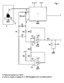
- a metallic burner 7 arranged in a combustion chamber 6 is electrically grounded GND connected. Furthermore, a single ionization electrode 5 is provided, which at The presence of a flame 2 on the burner delivers an ionization current.
- the Ionization electrode 5 is connected to an evaluation circuit 1.
- This evaluation circuit 1 is connected to ground GND and to two supply voltages U _loni and Ub1. On the output side, the evaluation circuit 1, which essentially compares the magnitude of the ionization current with a predetermined value, supplies a digital flame signal at an output 3.
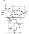
- a shunt resistor R shunt via two lines 8 and 9 is connected to a capacitor C1 is connected in parallel. Furthermore, resistors R1 and R2 are connected to each electrode of this capacitor C1 and are further connected to one another via a further capacitor C2, this capacitor C2 being connected to non-inverting inputs 10, 11 of two differential amplifiers OP1, OP2. These differential amplifiers OP1, OP2 are connected to ground GND and to a supply voltage Ub2.
- the inverting inputs 12, 13 of the two differential amplifiers 6, 7 are over Resistors R3, R5 connected to outputs of the differential amplifiers OP1, OP2, the inverting input of the differential amplifier OP1 via a resistor R4 with the Resistor R5 and the output of the differential amplifier OP2 is connected.
- a supply voltage Ub1 connected via a resistor R6.
- the output of the differential amplifier OP1 is through a resistor R7 and one to ground GND connected R / C parallel circuit R8 / C3 with an output terminal 4 connected, which carries a voltage signal that the DC component of the Ionization current is proportional, which flows between the electrode and ground GND.
- circuit part B in Fig. 2 corresponds to circuit part B in Fig. 2.
- the evaluation circuit 1 can, for example, that Circuit part A in Fig. 2 correspond.
- an AC voltage source U_loni is connected via a resistor R155 and a capacitor C150 connected in series therewith to the ionization electrode 5, which is arranged near the flame zone 2 of the burner 7.
- the flame is represented by an equivalent circuit diagram, which comprises a high-resistance resistor R flame and a diode D flame connected in series therewith, this series connection being connected to the ground GND of the burner 7.
- the ionization electrode 5 is further connected to an evaluation circuit.
- This includes a voltage divider circuit consisting of one with the ionization electrode 5 connected series connection of resistors R153 and R154 on the one hand and one Resistor R163 with a positive pole of a DC voltage source Ub1 connected is.
- a capacitor C154 is connected in parallel with the resistor R163 which is also connected to the base of a pnp transistor T152, the emitter of which the positive pole of the DC voltage source Ub is connected.
- the collector of the Transistor T152 is connected to burner ground GND via a resistor R164, which is connected to the negative pole GND of the DC voltage source Ub.
- This signal device comprises a capacitor C152 with a parallel resistor R165 which is connected in series with a diode D150 and another capacitor C151, wherein the latter with a base connection of a transistor T150, a collector connection of a Transistor T151 and a resistor R152 with the positive pole of the DC voltage source Ub is connected.
- the cathode of the diode D150 is also included the base connection of the transistor T151 and via a resistor R159 with the Burner mass connected.
- the capacitor C152 and the anode of the diode D150 are through a resistor R158 also connected to the burner mass.
- the emitter of transistor T151 is connected to the burner ground via a resistor R161, or the negative pole GND of the DC voltage source Ub, the emitter of transistor T150 through this resistor and one connected in series with it Resistor R162 is connected to the emitter of transistor T151.
- the collector of the Transistor T150 is connected directly to the positive pole of the DC voltage source Ub.
- Resistors R157 and R160 connected to the display signals _Flame 1 and _Flamme2.
- FIG. 2 shows the interconnection of the evaluation circuit 1 from FIG. 1, corresponding to FIG. 3, shown with the evaluation circuit B described above.
- the circuit is designed so that component faults always, even in connection with a independent secondary errors, either lead to a static output signal, or the Do not influence the function of the circuit or only in terms of sensitivity. This enables the use e.g. in automatic burner controls according to EN 298.
- the AC signal is suppressed with the aid of the capacitors C1 and C2.
- the high-resistance dimensioning of the resistors R1 and R2 in comparison to R shunt and R153, R154 ensures that, in the event of component errors in the circuit part B, the digital output of the evaluation circuit A, or an alternative evaluation circuit 1 according to FIG. 1, either continues to function properly or that there is a static _Flame output signal, regardless of whether a flame is actually present, so that the fault can be detected by a downstream logic.
- This enables the entire circuit to be used, for example, in automatic burner controls according to EN 298.
Landscapes
- Engineering & Computer Science (AREA)
- Chemical & Material Sciences (AREA)
- Combustion & Propulsion (AREA)
- Mechanical Engineering (AREA)
- General Engineering & Computer Science (AREA)
- Other Investigation Or Analysis Of Materials By Electrical Means (AREA)
- Control Of Combustion (AREA)
Abstract
Description
Fig. 1 eine schematische erfindungsgemäße Flammenüberwachungsschaltung und Fig. 2 und 3 Details aus Fig. 1.
Claims (4)
- Flammenüberwachungsschaltung für einen aus Metall bestehenden Brenner, der auf einem elektrischen Potential liegt, mit einer lonisationselektrode (3) und einer Auswerteschaltung (1), die ein digitales Ausgangssignal liefert, dadurch gekennzeichnet, dass die lonisationselektrode (3) mit einem Signaleingang der Auswerteschaltung (1) verbunden ist, an welche weiterhin ein Shunt-Widerstand (Rshunt) zur Entkopplung eines dem lonisationsstrom proportionalen Signales angeschlossen ist.
- Flammenüberwachungsschaltung nach Anspruch 1, dadurch gekennzeichnet, dass die Auswerteschaltung (B) eine gegenüber dem Shunt-Widerstand hochohmige R/C-Schaltung (C1, R1, R2) zur Filterung des Wechselstromanteiles des ausgekoppelten Signales aufweist.
- Flammenüberwachungsschaltung nach einem der Ansprüche 1 oder 2, dadurch gekennzeichnet, dass zur Erfassung der zum lonisationsstrom proportionalen Messgröße ein Differenzverstärker (6, 7) mit nachgeschalteter Messbereichsanpassung vorgesehen ist.
- Flammenüberwachungsschaltung nach einem der Ansprüche 1 bis 3, dadurch gekennzeichnet, dass der Auswerteschaltung (B) ein Analog-Digital-Konverter nachgeschaltet ist.
Priority Applications (1)
| Application Number | Priority Date | Filing Date | Title |
|---|---|---|---|
| AT01128091T ATE340969T1 (de) | 2000-12-01 | 2001-11-27 | Flammenüberwachungsschaltung |
Applications Claiming Priority (4)
| Application Number | Priority Date | Filing Date | Title |
|---|---|---|---|
| DE10061255 | 2000-12-01 | ||
| DE10061255 | 2000-12-01 | ||
| AT0181001A AT414179B (de) | 2001-11-19 | 2001-11-19 | Flammenüberwachungsschaltung |
| AT18102001 | 2001-11-19 |
Publications (3)
| Publication Number | Publication Date |
|---|---|
| EP1211461A2 true EP1211461A2 (de) | 2002-06-05 |
| EP1211461A3 EP1211461A3 (de) | 2004-04-14 |
| EP1211461B1 EP1211461B1 (de) | 2006-09-27 |
Family
ID=25608543
Family Applications (1)
| Application Number | Title | Priority Date | Filing Date |
|---|---|---|---|
| EP20010128091 Expired - Lifetime EP1211461B1 (de) | 2000-12-01 | 2001-11-27 | Flammenüberwachungsschaltung |
Country Status (5)
| Country | Link |
|---|---|
| EP (1) | EP1211461B1 (de) |
| DE (2) | DE50111086D1 (de) |
| DK (1) | DK1211461T3 (de) |
| ES (1) | ES2272397T3 (de) |
| PT (1) | PT1211461E (de) |
Cited By (1)
| Publication number | Priority date | Publication date | Assignee | Title |
|---|---|---|---|---|
| ITTO20090019A1 (it) * | 2009-01-14 | 2010-07-15 | Bitron Spa | Dispositivo circuitale per la rilevazione della fiamma in un bruciatore di gas |
Families Citing this family (1)
| Publication number | Priority date | Publication date | Assignee | Title |
|---|---|---|---|---|
| US9696034B2 (en) * | 2013-03-04 | 2017-07-04 | Clearsign Combustion Corporation | Combustion system including one or more flame anchoring electrodes and related methods |
Family Cites Families (3)
| Publication number | Priority date | Publication date | Assignee | Title |
|---|---|---|---|---|
| GB1277402A (en) * | 1968-08-27 | 1972-06-14 | United Gas Industries Ltd | Flame detection system |
| JPS563829A (en) * | 1979-06-20 | 1981-01-16 | Seihoku Sangyo Kk | Oxygen shortage detecting device for combustion appliance |
| JPH1019249A (ja) * | 1996-06-27 | 1998-01-23 | Toto Ltd | 異常燃焼検出装置 |
-
2001
- 2001-11-27 DE DE50111086T patent/DE50111086D1/de not_active Expired - Lifetime
- 2001-11-27 DK DK01128091T patent/DK1211461T3/da active
- 2001-11-27 EP EP20010128091 patent/EP1211461B1/de not_active Expired - Lifetime
- 2001-11-27 ES ES01128091T patent/ES2272397T3/es not_active Expired - Lifetime
- 2001-11-27 PT PT01128091T patent/PT1211461E/pt unknown
- 2001-11-27 DE DE10159225A patent/DE10159225A1/de not_active Withdrawn
Cited By (1)
| Publication number | Priority date | Publication date | Assignee | Title |
|---|---|---|---|---|
| ITTO20090019A1 (it) * | 2009-01-14 | 2010-07-15 | Bitron Spa | Dispositivo circuitale per la rilevazione della fiamma in un bruciatore di gas |
Also Published As
| Publication number | Publication date |
|---|---|
| DK1211461T3 (da) | 2007-01-29 |
| EP1211461B1 (de) | 2006-09-27 |
| DE50111086D1 (de) | 2006-11-09 |
| EP1211461A3 (de) | 2004-04-14 |
| ES2272397T3 (es) | 2007-05-01 |
| DE10159225A1 (de) | 2002-07-11 |
| PT1211461E (pt) | 2007-01-31 |
Similar Documents
| Publication | Publication Date | Title |
|---|---|---|
| DE4324863C2 (de) | Schaltungsanordnung zur Flammerkennung | |
| DE19502402C2 (de) | Verbrennungsaussetzer-Abtastschaltung für eine Brennkraftmaschine | |
| DE3340395A1 (de) | Spannungsregler | |
| DE10023273A1 (de) | Messeinrichtung für eine Flamme | |
| EP0514839A2 (de) | Messschaltung zur Messung einer Kapazität | |
| EP0386431B1 (de) | Schaltungsanordnung zur Messung der Primärspannung einer Zündspule | |
| DE3824556C2 (de) | Symmetrische Eingangsschaltung für Hochfrequenzverstärker | |
| DE69212364T2 (de) | Schaltkreis zur Erkennung von Kurzschlüssen von Steuereinrichtungen für induktive Lasten | |
| EP1211461B1 (de) | Flammenüberwachungsschaltung | |
| AT414179B (de) | Flammenüberwachungsschaltung | |
| DE8912984U1 (de) | Schnittstellenschaltung zwischen zwei an unterschiedlichen Betriebsspannungen betriebenen elektrischen Schaltungen | |
| DE2708274B2 (de) | Schaltungsanordnung zur Erzeugung eines Ausgangsimpulses, dessen Dauer nur einen Bruchteil der Dauer des Eingangsimpulses beträgt | |
| EP0432280A1 (de) | Schnittstelle zwischen zwei an unterschiedlichen Betriebsspannungen betriebenen elektrischen Schaltungen | |
| EP1211460B1 (de) | Flammenwächterschaltung | |
| DE2358818A1 (de) | Verfahren zur anzeige eines von einer kollektor-elektrode eines massen-spektrometers abgegebenen stroms und schaltung zur durchfuehrung des verfahrens | |
| DE2809993C3 (de) | Flammenwächterschaltung zur Überwachung einer Brennerflamme | |
| DE69734375T2 (de) | Bildanzeigevorrichtung mit Bus-gesteuerter Kompensationsschaltung unter Verwendung eines Pulsbreitenmodulationssignales # | |
| DE2836354C2 (de) | ||
| EP0530679B1 (de) | Längsregler zur Speisung eines gleichspannungsversorgten Verbrauchers sowie Anwendung | |
| EP0635638A2 (de) | Schaltungsanordnung zur Flammerkennung | |
| EP0914559A1 (de) | Schaltungsanordnung zur messung der zündspulenprimärspannung einer zündanlage einer brennkraftmaschine | |
| DE10033540C2 (de) | Einrichtung zum Erzeugen eines Referenzstromes | |
| DE1276734B (de) | Verstaerkerschaltung mit automatischer Verstaerkungsregelung | |
| AT350164B (de) | Elektronische ueberwachungseinrichtung fuer brenner, insbesondere gasbrenner | |
| DE1203863B (de) | Gleichstromversorgungsanlage mit Zweipunkt-Spannungsregelung |
Legal Events
| Date | Code | Title | Description |
|---|---|---|---|
| PUAI | Public reference made under article 153(3) epc to a published international application that has entered the european phase |
Free format text: ORIGINAL CODE: 0009012 |
|
| AK | Designated contracting states |
Kind code of ref document: A2 Designated state(s): AT BE CH CY DE DK ES FI FR GB GR IE IT LI LU MC NL PT SE TR |
|
| AX | Request for extension of the european patent |
Free format text: AL;LT;LV;MK;RO;SI |
|
| PUAL | Search report despatched |
Free format text: ORIGINAL CODE: 0009013 |
|
| AK | Designated contracting states |
Kind code of ref document: A3 Designated state(s): AT BE CH CY DE DK ES FI FR GB GR IE IT LI LU MC NL PT SE TR |
|
| AX | Request for extension of the european patent |
Extension state: AL LT LV MK RO SI |
|
| 17P | Request for examination filed |
Effective date: 20040311 |
|
| AKX | Designation fees paid |
Designated state(s): AT BE CH CY DE DK ES FI FR GB GR IE IT LI LU MC NL PT SE TR |
|
| GRAP | Despatch of communication of intention to grant a patent |
Free format text: ORIGINAL CODE: EPIDOSNIGR1 |
|
| GRAS | Grant fee paid |
Free format text: ORIGINAL CODE: EPIDOSNIGR3 |
|
| GRAA | (expected) grant |
Free format text: ORIGINAL CODE: 0009210 |
|
| AK | Designated contracting states |
Kind code of ref document: B1 Designated state(s): AT BE CH CY DE DK ES FI FR GB GR IE IT LI LU MC NL PT SE TR |
|
| PG25 | Lapsed in a contracting state [announced via postgrant information from national office to epo] |
Ref country code: FI Free format text: LAPSE BECAUSE OF FAILURE TO SUBMIT A TRANSLATION OF THE DESCRIPTION OR TO PAY THE FEE WITHIN THE PRESCRIBED TIME-LIMIT Effective date: 20060927 Ref country code: IT Free format text: LAPSE BECAUSE OF FAILURE TO SUBMIT A TRANSLATION OF THE DESCRIPTION OR TO PAY THE FEE WITHIN THE PRESCRIBED TIME-LIMIT;WARNING: LAPSES OF ITALIAN PATENTS WITH EFFECTIVE DATE BEFORE 2007 MAY HAVE OCCURRED AT ANY TIME BEFORE 2007. THE CORRECT EFFECTIVE DATE MAY BE DIFFERENT FROM THE ONE RECORDED. Effective date: 20060927 Ref country code: IE Free format text: LAPSE BECAUSE OF FAILURE TO SUBMIT A TRANSLATION OF THE DESCRIPTION OR TO PAY THE FEE WITHIN THE PRESCRIBED TIME-LIMIT Effective date: 20060927 |
|
| REG | Reference to a national code |
Ref country code: GB Ref legal event code: FG4D Free format text: NOT ENGLISH |
|
| REG | Reference to a national code |
Ref country code: CH Ref legal event code: EP |
|
| REG | Reference to a national code |
Ref country code: IE Ref legal event code: FG4D Free format text: LANGUAGE OF EP DOCUMENT: GERMAN |
|
| REF | Corresponds to: |
Ref document number: 50111086 Country of ref document: DE Date of ref document: 20061109 Kind code of ref document: P |
|
| PG25 | Lapsed in a contracting state [announced via postgrant information from national office to epo] |
Ref country code: MC Free format text: LAPSE BECAUSE OF NON-PAYMENT OF DUE FEES Effective date: 20061130 |
|
| PG25 | Lapsed in a contracting state [announced via postgrant information from national office to epo] |
Ref country code: SE Free format text: LAPSE BECAUSE OF FAILURE TO SUBMIT A TRANSLATION OF THE DESCRIPTION OR TO PAY THE FEE WITHIN THE PRESCRIBED TIME-LIMIT Effective date: 20061227 |
|
| REG | Reference to a national code |
Ref country code: DK Ref legal event code: T3 |
|
| GBT | Gb: translation of ep patent filed (gb section 77(6)(a)/1977) |
Effective date: 20070110 |
|
| REG | Reference to a national code |
Ref country code: PT Ref legal event code: SC4A Free format text: AVAILABILITY OF NATIONAL TRANSLATION Effective date: 20061219 |
|
| ET | Fr: translation filed | ||
| REG | Reference to a national code |
Ref country code: IE Ref legal event code: FD4D |
|
| REG | Reference to a national code |
Ref country code: ES Ref legal event code: FG2A Ref document number: 2272397 Country of ref document: ES Kind code of ref document: T3 |
|
| PLBE | No opposition filed within time limit |
Free format text: ORIGINAL CODE: 0009261 |
|
| STAA | Information on the status of an ep patent application or granted ep patent |
Free format text: STATUS: NO OPPOSITION FILED WITHIN TIME LIMIT |
|
| 26N | No opposition filed |
Effective date: 20070628 |
|
| PG25 | Lapsed in a contracting state [announced via postgrant information from national office to epo] |
Ref country code: GR Free format text: LAPSE BECAUSE OF FAILURE TO SUBMIT A TRANSLATION OF THE DESCRIPTION OR TO PAY THE FEE WITHIN THE PRESCRIBED TIME-LIMIT Effective date: 20061228 |
|
| PG25 | Lapsed in a contracting state [announced via postgrant information from national office to epo] |
Ref country code: LU Free format text: LAPSE BECAUSE OF NON-PAYMENT OF DUE FEES Effective date: 20061127 |
|
| PG25 | Lapsed in a contracting state [announced via postgrant information from national office to epo] |
Ref country code: CY Free format text: LAPSE BECAUSE OF FAILURE TO SUBMIT A TRANSLATION OF THE DESCRIPTION OR TO PAY THE FEE WITHIN THE PRESCRIBED TIME-LIMIT Effective date: 20060927 |
|
| PGFP | Annual fee paid to national office [announced via postgrant information from national office to epo] |
Ref country code: BE Payment date: 20081007 Year of fee payment: 8 |
|
| BERE | Be: lapsed |
Owner name: VAILLANT G.M.B.H. Effective date: 20091130 |
|
| PG25 | Lapsed in a contracting state [announced via postgrant information from national office to epo] |
Ref country code: BE Free format text: LAPSE BECAUSE OF NON-PAYMENT OF DUE FEES Effective date: 20091130 |
|
| PGFP | Annual fee paid to national office [announced via postgrant information from national office to epo] |
Ref country code: AT Payment date: 20101008 Year of fee payment: 10 |
|
| PGFP | Annual fee paid to national office [announced via postgrant information from national office to epo] |
Ref country code: FR Payment date: 20111020 Year of fee payment: 11 Ref country code: DK Payment date: 20111012 Year of fee payment: 11 Ref country code: CH Payment date: 20111012 Year of fee payment: 11 Ref country code: NL Payment date: 20111017 Year of fee payment: 11 |
|
| REG | Reference to a national code |
Ref country code: NL Ref legal event code: V1 Effective date: 20130601 |
|
| REG | Reference to a national code |
Ref country code: CH Ref legal event code: PL |
|
| REG | Reference to a national code |
Ref country code: DK Ref legal event code: EBP |
|
| REG | Reference to a national code |
Ref country code: AT Ref legal event code: MM01 Ref document number: 340969 Country of ref document: AT Kind code of ref document: T Effective date: 20121127 |
|
| PG25 | Lapsed in a contracting state [announced via postgrant information from national office to epo] |
Ref country code: LI Free format text: LAPSE BECAUSE OF NON-PAYMENT OF DUE FEES Effective date: 20121130 Ref country code: AT Free format text: LAPSE BECAUSE OF NON-PAYMENT OF DUE FEES Effective date: 20121127 Ref country code: CH Free format text: LAPSE BECAUSE OF NON-PAYMENT OF DUE FEES Effective date: 20121130 |
|
| REG | Reference to a national code |
Ref country code: FR Ref legal event code: ST Effective date: 20130731 |
|
| PG25 | Lapsed in a contracting state [announced via postgrant information from national office to epo] |
Ref country code: NL Free format text: LAPSE BECAUSE OF NON-PAYMENT OF DUE FEES Effective date: 20130601 |
|
| PG25 | Lapsed in a contracting state [announced via postgrant information from national office to epo] |
Ref country code: DK Free format text: LAPSE BECAUSE OF NON-PAYMENT OF DUE FEES Effective date: 20121130 |
|
| PG25 | Lapsed in a contracting state [announced via postgrant information from national office to epo] |
Ref country code: FR Free format text: LAPSE BECAUSE OF NON-PAYMENT OF DUE FEES Effective date: 20121130 |
|
| PGFP | Annual fee paid to national office [announced via postgrant information from national office to epo] |
Ref country code: TR Payment date: 20201102 Year of fee payment: 20 |
|
| PGFP | Annual fee paid to national office [announced via postgrant information from national office to epo] |
Ref country code: IT Payment date: 20201130 Year of fee payment: 20 Ref country code: DE Payment date: 20201028 Year of fee payment: 20 Ref country code: ES Payment date: 20201201 Year of fee payment: 20 Ref country code: GB Payment date: 20201027 Year of fee payment: 20 Ref country code: PT Payment date: 20201021 Year of fee payment: 20 |
|
| REG | Reference to a national code |
Ref country code: DE Ref legal event code: R071 Ref document number: 50111086 Country of ref document: DE |
|
| REG | Reference to a national code |
Ref country code: GB Ref legal event code: PE20 Expiry date: 20211126 |
|
| PG25 | Lapsed in a contracting state [announced via postgrant information from national office to epo] |
Ref country code: PT Free format text: LAPSE BECAUSE OF EXPIRATION OF PROTECTION Effective date: 20211207 Ref country code: GB Free format text: LAPSE BECAUSE OF EXPIRATION OF PROTECTION Effective date: 20211126 |
|
| REG | Reference to a national code |
Ref country code: ES Ref legal event code: FD2A Effective date: 20220405 |
|
| PG25 | Lapsed in a contracting state [announced via postgrant information from national office to epo] |
Ref country code: ES Free format text: LAPSE BECAUSE OF EXPIRATION OF PROTECTION Effective date: 20211128 |