EP1211461B1 - Flammenüberwachungsschaltung - Google Patents
Flammenüberwachungsschaltung Download PDFInfo
- Publication number
- EP1211461B1 EP1211461B1 EP20010128091 EP01128091A EP1211461B1 EP 1211461 B1 EP1211461 B1 EP 1211461B1 EP 20010128091 EP20010128091 EP 20010128091 EP 01128091 A EP01128091 A EP 01128091A EP 1211461 B1 EP1211461 B1 EP 1211461B1
- Authority
- EP
- European Patent Office
- Prior art keywords
- circuit
- flame
- resistor
- flame monitoring
- transistor
- Prior art date
- Legal status (The legal status is an assumption and is not a legal conclusion. Google has not performed a legal analysis and makes no representation as to the accuracy of the status listed.)
- Expired - Lifetime
Links
- 238000012544 monitoring process Methods 0.000 title claims description 13
- 238000011156 evaluation Methods 0.000 claims description 21
- 238000001914 filtration Methods 0.000 claims description 2
- 230000006978 adaptation Effects 0.000 claims 1
- 239000003990 capacitor Substances 0.000 description 14
- 230000011664 signaling Effects 0.000 description 3
- 230000035945 sensitivity Effects 0.000 description 2
- 230000003068 static effect Effects 0.000 description 2
- 238000002485 combustion reaction Methods 0.000 description 1
- 238000012937 correction Methods 0.000 description 1
- 230000008878 coupling Effects 0.000 description 1
- 238000010168 coupling process Methods 0.000 description 1
- 238000005859 coupling reaction Methods 0.000 description 1
- 230000007423 decrease Effects 0.000 description 1
- 238000013461 design Methods 0.000 description 1
- 238000001514 detection method Methods 0.000 description 1
- 238000010586 diagram Methods 0.000 description 1
- 230000000977 initiatory effect Effects 0.000 description 1
- 238000000034 method Methods 0.000 description 1
Images

Classifications
-
- F—MECHANICAL ENGINEERING; LIGHTING; HEATING; WEAPONS; BLASTING
- F23—COMBUSTION APPARATUS; COMBUSTION PROCESSES
- F23N—REGULATING OR CONTROLLING COMBUSTION
- F23N5/00—Systems for controlling combustion
- F23N5/02—Systems for controlling combustion using devices responsive to thermal changes or to thermal expansion of a medium
- F23N5/12—Systems for controlling combustion using devices responsive to thermal changes or to thermal expansion of a medium using ionisation-sensitive elements, i.e. flame rods
- F23N5/123—Systems for controlling combustion using devices responsive to thermal changes or to thermal expansion of a medium using ionisation-sensitive elements, i.e. flame rods using electronic means
Definitions
- the invention relates to a flame monitoring circuit according to the preamble of the independent claim.
- a flame monitoring circuit is already known from document US-A-3,627,458.
- the aim of the invention is to avoid these disadvantages and to propose a flame monitoring circuit of the type mentioned, which is characterized by a simpler structure.
- the proposed measures has the advantage that only one ionization electrode is required for flame monitoring.
- a filtering of the alternating current components of the ionization signal is provided in a simple manner, wherein the removed DC voltage signal can be supplied to an amplifier circuit.
- the fail-safe flame monitoring circuit connected to the ionization electrode is not influenced in its safety by an analog detection circuit, as would be the case in the prior art. As a result, it is also possible to find the way out with only one ionization electrode.
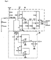
- FIG. 1 shows a schematic flame monitoring circuit according to the invention and FIGS. 2 and 3 show details from FIG. 1.
- a arranged in a combustion chamber 6 metallic burner 7 is electrically connected to ground GND. Furthermore, a single ionization electrode 5 is provided, which supplies an ionization current in the presence of a flame 2 at the burner. The ionization electrode 5 is connected to an evaluation circuit 1.
- This evaluation circuit 1 is connected to ground GND and to two supply voltages U _loni and Ub1. On the output side, the evaluation circuit 1, which essentially compares the size of the ionization current with a predetermined value, delivers a digital flame signal at an output 3.
- a shunt resistor R shunt is further connected via two lines 8 and 9, to which a capacitor C1 is connected in parallel. Further, resistors R1 and R2 are connected to each electrode of this capacitor C1, which are further connected to each other via a further capacitor C2, said capacitor C2 connected to non-inverting inputs 10, 11 of two differential amplifier OP1, OP2 is. These differential amplifiers OP1, OP2 are connected to ground GND and to a supply voltage Ub2.
- the inverting inputs 12, 13 of the two differential amplifiers 6, 7 are connected via resistors R3, R5 to outputs of the differential amplifier OP1, OP2, wherein the inverting input of the differential amplifier OP1 is connected via a resistor R4 to the resistor R5 and the output of the differential amplifier OP2 , Furthermore, a supply voltage Ub1 is connected to the inverting input 12 of the differential amplifier 7 via a resistor R6.
- the output of the differential amplifier OP1 is connected through a resistor R7 and connected to ground GND R / C parallel circuit R8 / C3 with an output terminal 4, which carries a voltage signal which is proportional to the DC component of the ionization current flowing between the electrode and ground GND ,
- This circuit described so far according to FIG. 1 except for the evaluation circuit 1 corresponds to the circuit part B in FIG. 2.
- the evaluation circuit 1 may correspond to the circuit part A in FIG. 2 by way of example.
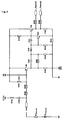
- an AC voltage source U_loni is connected via a resistor R155 and a capacitor C150 connected in series with the ionization electrode 5, which is arranged close to the flame zone 2 of the burner 7.
- the flame is represented by an equivalent circuit diagram which comprises a high-resistance resistor R flame and a diode D flame connected in series therewith, this series circuit being connected to the ground GND of the burner 7.
- the ionization electrode 5 is further connected to an evaluation circuit.
- This comprises a voltage divider circuit consisting of a connected in series with the ionization 5 series resistor R153 and R154 on the one hand and a resistor R163, which is connected to a positive pole of a DC voltage source Ub1.
- a capacitor C154 is connected in parallel with the resistor R163, to which also the base of a pnp transistor T152 is connected, whose emitter is connected to the positive pole of the DC voltage source Ub.
- the collector of the transistor T152 is connected via a resistor R164 to the burner ground GND, which is connected to the negative pole GND of the DC voltage source Ub.
- a signal device is further connected, which is also connected to the positive pole of the DC voltage source Ub and the negative pole GND.
- This signal device comprises a capacitor C152 with parallel resistor R165, which is connected in series with a diode D150 and another capacitor C151, the latter having a base terminal of a transistor T150, a collector terminal of a transistor T151 and a resistor R152 to the positive pole of the DC voltage source Ub is connected.
- the cathode of the diode D150 is further connected to the base terminal of the transistor T151 and via a resistor R159 to the burner mass.
- the capacitor C152 and the anode of the diode D150 are also connected to the burner mass via a resistor R158.
- the emitter of the transistor T151 is connected via a resistor R161 to the burner mass, or the negative pole GND of the DC voltage source Ub, wherein the emitter of the transistor T150 is connected via this resistor and a resistor R162 connected in series with the emitter of the transistor T151.
- the collector of the transistor T150 is directly connected to the positive pole of the DC voltage source Ub.
- the display signals _Flamme 1 and _Flamme2 are connected via resistors R157 and R160.
- FIG. 2 shows the interconnection of the evaluation circuit 1 from FIG. 1, corresponding to FIG. 3, with the evaluation circuit B described at the beginning.
- the AC voltage applied to the base of T152 is insufficient to drive transistor T152.
- Transistor T152 is permanently disabled. This also turns off the transistor T151 and the transistor T150 is turned on.
- the potential at the _Flame1 and optional second _Flame2 displays is a high potential, meaning that no flame is detected.
- the transistor T150 blocks permanently and the indications _flame1 and _flame2 are applied to a low level resulting essentially from the voltage divider formed by the resistors R152 and R161. If the potential at the base of the transistor T152 is so small at low-resistance flame that it is permanently driven, then the transistor T151 is also permanently driven via the resistor R165 and the diode D150 and the transistor T150 is turned off. In this case, a low level is also applied to the _Flame1 and _Flame2 displays, which in turn corresponds to a detected flame.
- a hysteresis behavior can be set. Via the resistors R164, R165, R158 and R159 in connection with the capacitors C152 and C151, the sensitivity of the evaluation circuit or the signaling device can be adjusted.
- the circuit is designed so that component faults either always lead to a static output signal, even in conjunction with an independent secondary fault, or do not affect the function of the circuit or only in terms of sensitivity. This allows the use of e.g. in gas burner control units according to EN 298.
- a voltage proportional to the ionization current which is caused by I1 at the flame monitor input at the resistor Rshunt is tapped off via the resistors R1 and R2. With the help of capacitors C1 and C2, the AC signal is suppressed.
- R154 high-impedance dimensioning of the resistors R1 and R2 ensures that in case of component errors in the circuit part B, the digital output of the evaluation circuit A, or an alternative evaluation circuit 1 of FIG. 1, either continue to work properly or in that a static output signal _flame is present, regardless of whether a flame is actually present, so that the error can be detected by a downstream logic.
- This allows the use of the complete circuit, eg in automatic gas burner control units according to EN 298.
Landscapes
- Engineering & Computer Science (AREA)
- Chemical & Material Sciences (AREA)
- Combustion & Propulsion (AREA)
- Mechanical Engineering (AREA)
- General Engineering & Computer Science (AREA)
- Other Investigation Or Analysis Of Materials By Electrical Means (AREA)
- Control Of Combustion (AREA)
Description
- Die Erfindung bezieht sich auf eine Flammenüberwachungsschaltung gemäß dem Oberbegriff des unabhängigen Anspruches. Eine solche Schaltung ist aus Dokument US-A-3 627 458 schon bekannt.
- Bei bekannten derartigen Flammenüberwachungsschaltungen wird der lonisationsstrom durch die Flamme gemessen. Dabei benötigen die bekannten derartigen Lösungen eine zweite lonisationselektrode zusätzlich zu der eigentlichen Überwachungselektrode, deren Signal durch eine fehlersichere digitalen Flammenwächterschaltung ausgewertet wird.
- Dabei ergibt sich jedoch durch die erforderliche zweite Elektrode der Nachteil eines entsprechend hohen konstruktiven Aufwandes, der insbesondere durch die erforderlichen Durchführungen der Leitungen und die zweite Elektrode selbst, sowie deren Befestigung bedingt ist.
- Ziel der Erfindung ist es, diese Nachteile zu vermeiden und eine Flammenüberwachungsschaltung der eingangs erwähnten Art vorzuschlagen, die sich durch einen einfacheren Aufbau auszeichnet.
- Erfindungsgemäß wird dies bei einer Flammenüberwachungsschaltung der eingangs erwähnten Art durch die kennzeichnenden Merkmale des unabhängigen Anspruches erreicht.
- Durch die vorgeschlagenen Maßnahmen ergibt sich der Vorteil, dass lediglich eine lonisationselektrode zur Flammenüberwachung erforderlich ist. Dabei ist auf einfache Weise eine Ausfilterung der Wechselstromanteile des lonisationssignales vorgesehen, wobei das abgenommene Gleichspannungssignal einer Verstärkerschaltung zugeführt werden kann.
- Dabei wird die an die lonisationselektrode geschaltete fehlersichere Flammenüberwachungsschaltung in ihrer Sicherheit nicht durch eine analoge Erfassungsschaltung beeinflusst, wie dies beim Stand der Technik der Fall wäre. Dadurch ist es auch möglich, mit lediglich einer lonisationselektrode das Auslangen zu finden.
- Durch die Merkmale des Anspruches 2 ergibt sich der Vorteil, dass das lonisationssignal durch die Auskopplung des von diesen abgeleiteten Signales kaum beeinflusst wird, wodurch ein entsprechend hohes Maß an Genauigkeit der Auswertung ermöglicht wird.
- Durch die Merkmale des Anspruches 3 ergibt sich der Vorteil, dass die Auswertung das Signal kaum belastet und dadurch ein entsprechend hohes Maß an Genauigkeit der Auswertung erreicht werden kann.
- Durch die Merkmale des Anspruches 4 ergibt sich der Vorteil, dass ein sehr eindeutiges Ausgangssignal sichergestellt ist, das auch für die eine Signalisierung oder die Einleitung eines Korrekturvorganges verwendet werden kann.
- Ein Ausführungsbeispiel der Erfindung wird nun anhand der Figuren 1, 2 und 3 der Zeichnungen näher erläutert.
- Es zeigen:
Fig. 1 eine schematische erfindungsgemäße Flammenüberwachungsschaltung und Fig. 2 und 3 Details aus Fig. 1. - In allen Darstellungen bedeuten gleiche Bezugszeichen die gleichen Einzelheiten.
- Ein in einer Brennkammer 6 angeordneter metallischer Brenner 7 ist elektrisch mit Masse GND verbunden. Weiter ist eine einzige lonisationselektrode 5 vorgesehen, die bei Vorhandensein einer Flamme 2 am Brenner einen lonisationsstrom liefert. Die lonisationselektrode 5 ist mit einer Auswerteschaltung 1 verbunden.
- Diese Auswerteschaltung 1 ist an Masse GND und an zwei Versorgungsspannungen U_loni und Ub1 angeschlossen. Ausgangsseitig liefert die Auswerteschaltung 1, die im wesentlichen die Größe des lonisationsstromes mit einem vorgegebenen Wert vergleicht, ein digitales Flammensignal an einem Ausgang 3.
- An die Auswerteschaltung 1 ist weiter ein Shunt-Widerstand Rshunt über zwei Leitungen 8 und 9 angeschlossen, zu dem ein Kondensator C1 parallel geschaltet ist. Weiter sind an jede Elektrode dieses Kondensators C1 Widerstände R1 bzw. R2 angeschlossen, die weiter über einen weiteren Kondensator C2 miteinander verbunden sind, wobei dieser Kondensator C2 mit nicht-invertierenden Eingängen 10, 11 zweier Differenzverstärker OP1, OP2 verbunden ist. Diese Differenzverstärker OP1, OP2 sind an Masse GND und an eine Versorgungsspannung Ub2 angeschlossen.
- Die invertierenden Eingänge 12, 13 der beiden Differenzverstärker 6, 7 sind über Widerstände R3, R5 mit Ausgängen der Differenzverstärker OP1, OP2 verbunden, wobei der invertierende Eingang des Differenzverstärkers OP1 über einen Widerstand R4 mit dem Widerstand R5 und dem Ausgang des Differenzverstärkers OP2 verbunden ist. Weiter ist an den invertierenden Eingang 12 des Differenzverstärkers 7 eine Versorgungsspannung Ub1 über einen Widerstand R6 angeschlossen.
- Der Ausgang des Differenzverstärkers OP1 ist über einen Widerstand R7 und ein an Masse GND angeschlossene R/C-Parallelschaltung R8/C3 mit einer Ausgangsklemme 4 verbunden, die ein Spannungssignal führt, das dem Gleichstromanteil des lonisationsstromes proportional ist, der zwischen Elektrode und Masse GND fliesst.
- Diese bisher beschriebene Schaltung nach Fig. 1 ausgenommen der Auswerteschaltung 1 entspricht dem Schaltungsteil B in Fig. 2. Die Auswerteschaltung 1 kann beispielhaft dem Schaltungsteil A in Fig. 2 entsprechen.
- Beim Schaltungsteil A in Fig.2, entsprechend Fig. 3, der erfindungsgemäßen Flammenwächterschaltung ist eine Wechselspannungsquelle U_loni über einen Widerstand R155 und einen zu diesem in Reihe geschalteten Kondensator C150 mit der lonisationselektrode 5 verbunden, die nahe der Flammenzone 2 des Brenners 7 angeordnet ist. Dabei ist die Flamme durch ein Ersatzschaltbild dargestellt, das einen hochohmigen Widerstand RFlamme und eine zu diesem in Reihe geschalteten Diode DFlamme umfasst, wobei diese Reihenschaltung mit der Masse GND des Brenners 7 verbunden ist.
- Die lonisationselektrode 5 ist weiter mit einer Auswerteschaltung verbunden. Diese umfasst eine Spannungsteilerschaltung bestehend aus einer mit der lonisationselektrode 5 verbundenen Reihenschaltung der Widerstände R153 und R154 einerseits und eines Widerstandes R163, der mit einem positiven Pol einer Gleichspannungsquelle Ub1 verbunden ist. Dabei ist zum Widerstand R163 ein Kondensator C154 parallel geschaltet, an dem auch die die Basis eines pnp-Transistors T152 angeschlossen ist, dessen Emitter mit dem positiven Pol der Gleichspannungsquelle Ub angeschlossen ist. Der Kollektor des Transistors T152 ist über einen Widerstand R164 mit der Brennermasse GND verbunden, die mit dem negativen Pol GND der Gleichspannungsquelle Ub verbunden ist.
- An dem Kollektor des Transistors T152 ist weiter eine Signaleinrichtung angeschlossen, die ebenfalls mit dem positiven Pol der Gleichspannungsquelle Ub und deren negativen Pol GND angeschlossen ist.
- Diese Signaleinrichtung umfasst einen Kondensator C152 mit Parallelwiderstand R165, der in Reihe mit einer Diode D150 und einem weiteren Kondensator C151 geschaltet ist, wobei letzterer mit einem Basisanschluss eines Transistors T150, einem Kollektoranschluss eines Transistors T151 und über einen Widerstand R152 mit dem positiven Pol der Gleichspannungsquelle Ub verbunden ist. Die Kathode der Diode D150 ist dabei weiter mit dem Basisanschluss des Transistors T151 und über einen Widerstand R159 mit der Brennermasse verbunden.
- Der Kondensator C152 und die Anode der Diode D150 sind über einen Widerstand R158 ebenfalls mit der Brennermasse verbunden.
- Der Emitter des Transistors T151 ist über einen Widerstand R161 mit der Brennermasse, bzw. dem negativen Pol GND der Gleichspannnungsquelle Ub verbunden, wobei der Emitter des Transistors T150 über diesen Widerstand und einen zu diesem in Reihe geschalteten Widerstand R162 mit dem Emitter des Transistors T151 verbunden ist.. Der Kollektor des Transistors T150 ist direkt mit dem positiven Pol der Gleichspanungsquelle Ub verbunden.
- Zwischen dem Emitter des Transistors T150 und dem Widerstand R162 sind über Widerstände R157 und R160 die Anzeigesignale _Flamme 1 und _Flamme2 angeschlossen.
- In Fig. 2 ist die Zusammenschaltung der Auswerteschaltung 1 aus Fig.1, entsprechend Fig. 3, mit der Eingangs beschriebenen Auswerteschaltung B dargestellt.
- Die Funktion der Auswerteschaltung gemäß Fig.3 samt der Signaleinrichtung wird im folgenden erläutert.
- Ist keine Flamme vorhanden, wobei die Flamme im Sinne eines elektronischen Ersatzschaltbildes eine hochohmige Diodenstrecke mit dem Widerstand RFlamme in Reihe zur Diode DFlamme bildet, wird die an der lonisationselektrode loni anliegende Spannung U_loni über die Widerstände R153, R154 und R163 heruntergeteilt und in Kombination mit dem Kondensator C154 Tiefpass gefiltert. Die somit an der Basis von T152 anliegende Wechselspannung reicht nicht aus um den Transistor T152 anzusteuern. Der Transistor T152 ist dauerhaft gesperrt. Damit sperrt auch der Transistor T151 und der Transistor T150 ist durchgeschaltet. Das Potential an den Anzeigen _Flamme1 und der optionalen zweiten Anzeige _Flamme2 ist ein High-Potential, das bedeutet, dass keine Flamme erkannt wird.
- Bei vorhandener Flamme fließt bei der positiven Halbwelle von U_loni ein Strom von der lonisationselektrode loni zur Brennermasse, bzw. dem negativen Pol GND der Gleichspannungsquelle Ub. Dadurch sinkt das Potential an der Basis des Transistors T152 und während der negativen Halbwelle fängt dessen Emitter-Kollektorstrecke an zu leiten, was dazu führt, dass am Kollektor des Transistors T152 Spannungsimpulse erzeugt werden, die über den Kondensator C152 und Diode D150 auf die Basis des Transistors T151 übertragen werden und dieser leitend wird. Da sich der Kondensator C151 durch die Basis-Emitterstrecke des Transistors T151 umlädt, bleibt letzterer für einige Zeit leitend. Der Transistor T150 sperrt hierdurch dauerhaft und an den Anzeigen _Flamme1 und _Flamme2 liegt ein, sich im wesentlichen aus dem Spannungsteiler, der durch die Widerstände R152 und R161 gebildet ist, ergebender, Low-Pegel an. Wird bei niederohmiger Flamme das Potential an der Basis des Transistors T152 so klein, dass dieser dauerhaft angesteuert wird, wird über den Widerstand R165 und die Diode D150 der Transistor T151 ebenfalls dauerhaft angesteuert und der Transistor T150 sperrt. In diesem Fall liegt ebenfalls ein Low-Pegel an den Anzeigen _Flamme1 und _Flamme2 an, was wiederum einer erkannten Flamme entspricht.
- Durch geeignete Dimensionierung der Widerstände R161, R162, R152 kann ein Hystereseverhalten eingestellt werden. Über die Widerstände R164, R165, R158 und R159 in Verbindung mit den Kondensatoren C152 und C151 kann die Empfindlichkeit der Auswerteschaltung bzw. der Signaleinrichtung eingestellt werden.
- Die Schaltung ist so ausgelegt, dass Bauteilfehler immer, auch in Verbindung mit einem unabhängigen Zweitfehler, entweder zu einem statischen Ausgangsignal führen, oder die Funktion der Schaltung nicht oder nur im Hinblick auf die Empfindlichkeit beeinflussen. Dieses ermöglicht den Einsatz z.B. in Gasfeuerungsautomaten nach EN 298.
- Die Funktion der Auswerteschaltung B in Fig. 2 bzw. gemäß Fig.1 wird im folgenden erläutert.
- Eine dem lonisationsstrom proportionale Spannung, die durch I1 am Flammenwächtereingang an dem Widerstand Rshunt hervorgerufen wird, wird über die Widerstände R1 und R2 abgegriffen. Mit Hilfe der Kondensatoren C1 und C2 wird das Wechselspannungssignal unterdrückt. Die resultierende Gleichspannung UI1Gleichanteil wird gemäß UI_Ioni= a x UI1Gleichanteil + b verstärkt. Der Faktor a und der Offset b ergeben sich aus dem Verhältnis der Widerstände R4 und R3 mit R4=R5 und R3=R6, sowie dem Verhältnis R7 zu R8.
- Durch die im Vergleich zu Rshunt und R153, R154 hochohmige Dimensionierung der Widerstände R1 und R2 ist sichergestellt, dass bei Bauteilfehlern in dem Schaltungsteil B der digitale Ausgang der Auswerteschaltung A , oder einer alternativen Auswerteschaltung 1 gemäß Fig. 1, entweder weiterhin ordnungsgemäß funktioniert oder, dass ein statisches Ausgangssignal _Flamme anliegt, unabhängig davon, ob tatsächlich eine Flamme vorhanden ist, sodass der Fehler von einer nachgeschalteten Logik erkannt werden kann. Dieses ermöglicht den Einsatz der Gesamtschaltung z.B. in Gasfeuerungsautomaten nach EN 298.
Claims (4)
- Flammenüberwachungsschaltung für einen aus Metall bestehenden Brenner, der auf einem elektrischen Potential liegt, mit einer Ionisationselektrode (5) und einer Auswerteschaltung (1), die ein digitales Ausgangssignal liefert, dadurch gekennzeichnet, dass die lonisationselektrode (5) mit einem Signaleingang der Auswerteschaltung (1) verbunden ist, an welche weiterhin ein Shunt-Widerstand (Rshunt) zur Entkopplung eines dem lonisationsstrom proportionalen Signales angeschlossen ist.
- Flammenüberwachungsschaltung nach Anspruch 1, dadurch gekennzeichnet, dass die Auswerteschaltung (B) eine gegenüber dem Shunt-Widerstand hochohmige R/C-Schaltung (C1, R1, R2) zur Filterung des Wechselstromanteiles des ausgekoppelten Signales aufweist.
- Flammenüberwachungsschaltung nach einem der Ansprüche 1 oder 2, dadurch gekennzeichnet, dass zur Erfassung der zum Ionisationsstrom proportionalen Messgröße ein Differenzverstärker (6, 7) mit nachgeschalteter Messbereichsanpassung vorgesehen ist.
- Flammenüberwachungsschaltung nach einem der Ansprüche 1 bis 3, dadurch gekennzeichnet, dass der Auswerteschaltung (B) ein Analog-Digital-Konverter nachgeschaltet ist.
Priority Applications (1)
| Application Number | Priority Date | Filing Date | Title |
|---|---|---|---|
| AT01128091T ATE340969T1 (de) | 2000-12-01 | 2001-11-27 | Flammenüberwachungsschaltung |
Applications Claiming Priority (4)
| Application Number | Priority Date | Filing Date | Title |
|---|---|---|---|
| DE10061255 | 2000-12-01 | ||
| DE10061255 | 2000-12-01 | ||
| AT0181001A AT414179B (de) | 2001-11-19 | 2001-11-19 | Flammenüberwachungsschaltung |
| AT18102001 | 2001-11-19 |
Publications (3)
| Publication Number | Publication Date |
|---|---|
| EP1211461A2 EP1211461A2 (de) | 2002-06-05 |
| EP1211461A3 EP1211461A3 (de) | 2004-04-14 |
| EP1211461B1 true EP1211461B1 (de) | 2006-09-27 |
Family
ID=25608543
Family Applications (1)
| Application Number | Title | Priority Date | Filing Date |
|---|---|---|---|
| EP20010128091 Expired - Lifetime EP1211461B1 (de) | 2000-12-01 | 2001-11-27 | Flammenüberwachungsschaltung |
Country Status (5)
| Country | Link |
|---|---|
| EP (1) | EP1211461B1 (de) |
| DE (2) | DE50111086D1 (de) |
| DK (1) | DK1211461T3 (de) |
| ES (1) | ES2272397T3 (de) |
| PT (1) | PT1211461E (de) |
Families Citing this family (2)
| Publication number | Priority date | Publication date | Assignee | Title |
|---|---|---|---|---|
| ITTO20090019A1 (it) * | 2009-01-14 | 2010-07-15 | Bitron Spa | Dispositivo circuitale per la rilevazione della fiamma in un bruciatore di gas |
| US9696034B2 (en) * | 2013-03-04 | 2017-07-04 | Clearsign Combustion Corporation | Combustion system including one or more flame anchoring electrodes and related methods |
Family Cites Families (3)
| Publication number | Priority date | Publication date | Assignee | Title |
|---|---|---|---|---|
| GB1277402A (en) * | 1968-08-27 | 1972-06-14 | United Gas Industries Ltd | Flame detection system |
| JPS563829A (en) * | 1979-06-20 | 1981-01-16 | Seihoku Sangyo Kk | Oxygen shortage detecting device for combustion appliance |
| JPH1019249A (ja) * | 1996-06-27 | 1998-01-23 | Toto Ltd | 異常燃焼検出装置 |
-
2001
- 2001-11-27 DE DE50111086T patent/DE50111086D1/de not_active Expired - Lifetime
- 2001-11-27 DK DK01128091T patent/DK1211461T3/da active
- 2001-11-27 EP EP20010128091 patent/EP1211461B1/de not_active Expired - Lifetime
- 2001-11-27 ES ES01128091T patent/ES2272397T3/es not_active Expired - Lifetime
- 2001-11-27 PT PT01128091T patent/PT1211461E/pt unknown
- 2001-11-27 DE DE10159225A patent/DE10159225A1/de not_active Withdrawn
Also Published As
| Publication number | Publication date |
|---|---|
| DK1211461T3 (da) | 2007-01-29 |
| DE50111086D1 (de) | 2006-11-09 |
| EP1211461A3 (de) | 2004-04-14 |
| EP1211461A2 (de) | 2002-06-05 |
| ES2272397T3 (es) | 2007-05-01 |
| DE10159225A1 (de) | 2002-07-11 |
| PT1211461E (pt) | 2007-01-31 |
Similar Documents
| Publication | Publication Date | Title |
|---|---|---|
| DE3422716C2 (de) | ||
| DE4324863C2 (de) | Schaltungsanordnung zur Flammerkennung | |
| EP0514839A2 (de) | Messschaltung zur Messung einer Kapazität | |
| DE10023273A1 (de) | Messeinrichtung für eine Flamme | |
| DE3708892A1 (de) | Strommesseinrichtung, insbesondere zur bestimmung des motorstroms eines gleichstrommotors | |
| EP1211461B1 (de) | Flammenüberwachungsschaltung | |
| DE3803611C2 (de) | ||
| DE19839160A1 (de) | Verfahren und Schaltung zur Regelung eines Gasbrenners | |
| AT414179B (de) | Flammenüberwachungsschaltung | |
| DE2708274B2 (de) | Schaltungsanordnung zur Erzeugung eines Ausgangsimpulses, dessen Dauer nur einen Bruchteil der Dauer des Eingangsimpulses beträgt | |
| DE4039356C1 (de) | ||
| DE8912984U1 (de) | Schnittstellenschaltung zwischen zwei an unterschiedlichen Betriebsspannungen betriebenen elektrischen Schaltungen | |
| EP1211460B1 (de) | Flammenwächterschaltung | |
| EP0250028A2 (de) | Schaltungsanordnung zur Kompensation von temperatur- und nichttemperatur-bedingtem Driften eines kapazitiven Sensors | |
| DE2358818A1 (de) | Verfahren zur anzeige eines von einer kollektor-elektrode eines massen-spektrometers abgegebenen stroms und schaltung zur durchfuehrung des verfahrens | |
| EP0432280A1 (de) | Schnittstelle zwischen zwei an unterschiedlichen Betriebsspannungen betriebenen elektrischen Schaltungen | |
| DE4129345C2 (de) | ||
| DE2809993B2 (de) | Flammenwächterschaltung zur Überwachung einer Brennerflamme | |
| DE3809110C2 (de) | Einrichtung zur Gasmassenstrommessung | |
| DE3210890C2 (de) | ||
| DE19739317A1 (de) | Elektrische Schaltung für einen elektrochemischen Sensor | |
| DE10033540C2 (de) | Einrichtung zum Erzeugen eines Referenzstromes | |
| DE3305627C2 (de) | Schaltungsanordnung zur Überwachung des Arbeitsbereiches eines Operationsverstärkers | |
| DE1965426C3 (de) | Einrichtung zur Überwachung von Brennern in Feuerungsanlagen | |
| AT350164B (de) | Elektronische ueberwachungseinrichtung fuer brenner, insbesondere gasbrenner |
Legal Events
| Date | Code | Title | Description |
|---|---|---|---|
| PUAI | Public reference made under article 153(3) epc to a published international application that has entered the european phase |
Free format text: ORIGINAL CODE: 0009012 |
|
| AK | Designated contracting states |
Kind code of ref document: A2 Designated state(s): AT BE CH CY DE DK ES FI FR GB GR IE IT LI LU MC NL PT SE TR |
|
| AX | Request for extension of the european patent |
Free format text: AL;LT;LV;MK;RO;SI |
|
| PUAL | Search report despatched |
Free format text: ORIGINAL CODE: 0009013 |
|
| AK | Designated contracting states |
Kind code of ref document: A3 Designated state(s): AT BE CH CY DE DK ES FI FR GB GR IE IT LI LU MC NL PT SE TR |
|
| AX | Request for extension of the european patent |
Extension state: AL LT LV MK RO SI |
|
| 17P | Request for examination filed |
Effective date: 20040311 |
|
| AKX | Designation fees paid |
Designated state(s): AT BE CH CY DE DK ES FI FR GB GR IE IT LI LU MC NL PT SE TR |
|
| GRAP | Despatch of communication of intention to grant a patent |
Free format text: ORIGINAL CODE: EPIDOSNIGR1 |
|
| GRAS | Grant fee paid |
Free format text: ORIGINAL CODE: EPIDOSNIGR3 |
|
| GRAA | (expected) grant |
Free format text: ORIGINAL CODE: 0009210 |
|
| AK | Designated contracting states |
Kind code of ref document: B1 Designated state(s): AT BE CH CY DE DK ES FI FR GB GR IE IT LI LU MC NL PT SE TR |
|
| PG25 | Lapsed in a contracting state [announced via postgrant information from national office to epo] |
Ref country code: FI Free format text: LAPSE BECAUSE OF FAILURE TO SUBMIT A TRANSLATION OF THE DESCRIPTION OR TO PAY THE FEE WITHIN THE PRESCRIBED TIME-LIMIT Effective date: 20060927 Ref country code: IT Free format text: LAPSE BECAUSE OF FAILURE TO SUBMIT A TRANSLATION OF THE DESCRIPTION OR TO PAY THE FEE WITHIN THE PRESCRIBED TIME-LIMIT;WARNING: LAPSES OF ITALIAN PATENTS WITH EFFECTIVE DATE BEFORE 2007 MAY HAVE OCCURRED AT ANY TIME BEFORE 2007. THE CORRECT EFFECTIVE DATE MAY BE DIFFERENT FROM THE ONE RECORDED. Effective date: 20060927 Ref country code: IE Free format text: LAPSE BECAUSE OF FAILURE TO SUBMIT A TRANSLATION OF THE DESCRIPTION OR TO PAY THE FEE WITHIN THE PRESCRIBED TIME-LIMIT Effective date: 20060927 |
|
| REG | Reference to a national code |
Ref country code: GB Ref legal event code: FG4D Free format text: NOT ENGLISH |
|
| REG | Reference to a national code |
Ref country code: CH Ref legal event code: EP |
|
| REG | Reference to a national code |
Ref country code: IE Ref legal event code: FG4D Free format text: LANGUAGE OF EP DOCUMENT: GERMAN |
|
| REF | Corresponds to: |
Ref document number: 50111086 Country of ref document: DE Date of ref document: 20061109 Kind code of ref document: P |
|
| PG25 | Lapsed in a contracting state [announced via postgrant information from national office to epo] |
Ref country code: MC Free format text: LAPSE BECAUSE OF NON-PAYMENT OF DUE FEES Effective date: 20061130 |
|
| PG25 | Lapsed in a contracting state [announced via postgrant information from national office to epo] |
Ref country code: SE Free format text: LAPSE BECAUSE OF FAILURE TO SUBMIT A TRANSLATION OF THE DESCRIPTION OR TO PAY THE FEE WITHIN THE PRESCRIBED TIME-LIMIT Effective date: 20061227 |
|
| REG | Reference to a national code |
Ref country code: DK Ref legal event code: T3 |
|
| GBT | Gb: translation of ep patent filed (gb section 77(6)(a)/1977) |
Effective date: 20070110 |
|
| REG | Reference to a national code |
Ref country code: PT Ref legal event code: SC4A Free format text: AVAILABILITY OF NATIONAL TRANSLATION Effective date: 20061219 |
|
| ET | Fr: translation filed | ||
| REG | Reference to a national code |
Ref country code: IE Ref legal event code: FD4D |
|
| REG | Reference to a national code |
Ref country code: ES Ref legal event code: FG2A Ref document number: 2272397 Country of ref document: ES Kind code of ref document: T3 |
|
| PLBE | No opposition filed within time limit |
Free format text: ORIGINAL CODE: 0009261 |
|
| STAA | Information on the status of an ep patent application or granted ep patent |
Free format text: STATUS: NO OPPOSITION FILED WITHIN TIME LIMIT |
|
| 26N | No opposition filed |
Effective date: 20070628 |
|
| PG25 | Lapsed in a contracting state [announced via postgrant information from national office to epo] |
Ref country code: GR Free format text: LAPSE BECAUSE OF FAILURE TO SUBMIT A TRANSLATION OF THE DESCRIPTION OR TO PAY THE FEE WITHIN THE PRESCRIBED TIME-LIMIT Effective date: 20061228 |
|
| PG25 | Lapsed in a contracting state [announced via postgrant information from national office to epo] |
Ref country code: LU Free format text: LAPSE BECAUSE OF NON-PAYMENT OF DUE FEES Effective date: 20061127 |
|
| PG25 | Lapsed in a contracting state [announced via postgrant information from national office to epo] |
Ref country code: CY Free format text: LAPSE BECAUSE OF FAILURE TO SUBMIT A TRANSLATION OF THE DESCRIPTION OR TO PAY THE FEE WITHIN THE PRESCRIBED TIME-LIMIT Effective date: 20060927 |
|
| PGFP | Annual fee paid to national office [announced via postgrant information from national office to epo] |
Ref country code: BE Payment date: 20081007 Year of fee payment: 8 |
|
| BERE | Be: lapsed |
Owner name: VAILLANT G.M.B.H. Effective date: 20091130 |
|
| PG25 | Lapsed in a contracting state [announced via postgrant information from national office to epo] |
Ref country code: BE Free format text: LAPSE BECAUSE OF NON-PAYMENT OF DUE FEES Effective date: 20091130 |
|
| PGFP | Annual fee paid to national office [announced via postgrant information from national office to epo] |
Ref country code: AT Payment date: 20101008 Year of fee payment: 10 |
|
| PGFP | Annual fee paid to national office [announced via postgrant information from national office to epo] |
Ref country code: FR Payment date: 20111020 Year of fee payment: 11 Ref country code: DK Payment date: 20111012 Year of fee payment: 11 Ref country code: CH Payment date: 20111012 Year of fee payment: 11 Ref country code: NL Payment date: 20111017 Year of fee payment: 11 |
|
| REG | Reference to a national code |
Ref country code: NL Ref legal event code: V1 Effective date: 20130601 |
|
| REG | Reference to a national code |
Ref country code: CH Ref legal event code: PL |
|
| REG | Reference to a national code |
Ref country code: DK Ref legal event code: EBP |
|
| REG | Reference to a national code |
Ref country code: AT Ref legal event code: MM01 Ref document number: 340969 Country of ref document: AT Kind code of ref document: T Effective date: 20121127 |
|
| PG25 | Lapsed in a contracting state [announced via postgrant information from national office to epo] |
Ref country code: LI Free format text: LAPSE BECAUSE OF NON-PAYMENT OF DUE FEES Effective date: 20121130 Ref country code: AT Free format text: LAPSE BECAUSE OF NON-PAYMENT OF DUE FEES Effective date: 20121127 Ref country code: CH Free format text: LAPSE BECAUSE OF NON-PAYMENT OF DUE FEES Effective date: 20121130 |
|
| REG | Reference to a national code |
Ref country code: FR Ref legal event code: ST Effective date: 20130731 |
|
| PG25 | Lapsed in a contracting state [announced via postgrant information from national office to epo] |
Ref country code: NL Free format text: LAPSE BECAUSE OF NON-PAYMENT OF DUE FEES Effective date: 20130601 |
|
| PG25 | Lapsed in a contracting state [announced via postgrant information from national office to epo] |
Ref country code: DK Free format text: LAPSE BECAUSE OF NON-PAYMENT OF DUE FEES Effective date: 20121130 |
|
| PG25 | Lapsed in a contracting state [announced via postgrant information from national office to epo] |
Ref country code: FR Free format text: LAPSE BECAUSE OF NON-PAYMENT OF DUE FEES Effective date: 20121130 |
|
| PGFP | Annual fee paid to national office [announced via postgrant information from national office to epo] |
Ref country code: TR Payment date: 20201102 Year of fee payment: 20 |
|
| PGFP | Annual fee paid to national office [announced via postgrant information from national office to epo] |
Ref country code: IT Payment date: 20201130 Year of fee payment: 20 Ref country code: DE Payment date: 20201028 Year of fee payment: 20 Ref country code: ES Payment date: 20201201 Year of fee payment: 20 Ref country code: GB Payment date: 20201027 Year of fee payment: 20 Ref country code: PT Payment date: 20201021 Year of fee payment: 20 |
|
| REG | Reference to a national code |
Ref country code: DE Ref legal event code: R071 Ref document number: 50111086 Country of ref document: DE |
|
| REG | Reference to a national code |
Ref country code: GB Ref legal event code: PE20 Expiry date: 20211126 |
|
| PG25 | Lapsed in a contracting state [announced via postgrant information from national office to epo] |
Ref country code: PT Free format text: LAPSE BECAUSE OF EXPIRATION OF PROTECTION Effective date: 20211207 Ref country code: GB Free format text: LAPSE BECAUSE OF EXPIRATION OF PROTECTION Effective date: 20211126 |
|
| REG | Reference to a national code |
Ref country code: ES Ref legal event code: FD2A Effective date: 20220405 |
|
| PG25 | Lapsed in a contracting state [announced via postgrant information from national office to epo] |
Ref country code: ES Free format text: LAPSE BECAUSE OF EXPIRATION OF PROTECTION Effective date: 20211128 |