EP1211571B1 - Rouleau de développement avec un cylindre de développement transportant le développateur sans contrainte produite par un élément de régulation - Google Patents
Rouleau de développement avec un cylindre de développement transportant le développateur sans contrainte produite par un élément de régulation Download PDFInfo
- Publication number
- EP1211571B1 EP1211571B1 EP01310062A EP01310062A EP1211571B1 EP 1211571 B1 EP1211571 B1 EP 1211571B1 EP 01310062 A EP01310062 A EP 01310062A EP 01310062 A EP01310062 A EP 01310062A EP 1211571 B1 EP1211571 B1 EP 1211571B1
- Authority
- EP
- European Patent Office
- Prior art keywords
- developer
- developing sleeve
- developing
- surface roughness
- regulating member
- Prior art date
- Legal status (The legal status is an assumption and is not a legal conclusion. Google has not performed a legal analysis and makes no representation as to the accuracy of the status listed.)
- Expired - Lifetime
Links
- 230000001105 regulatory effect Effects 0.000 title claims description 43
- 230000003746 surface roughness Effects 0.000 claims description 33
- 238000007789 sealing Methods 0.000 claims description 6
- 238000010586 diagram Methods 0.000 description 14
- 230000003247 decreasing effect Effects 0.000 description 12
- 230000000694 effects Effects 0.000 description 5
- 230000015271 coagulation Effects 0.000 description 3
- 238000005345 coagulation Methods 0.000 description 3
- 238000010276 construction Methods 0.000 description 3
- 230000006866 deterioration Effects 0.000 description 3
- 238000005516 engineering process Methods 0.000 description 2
- 238000000034 method Methods 0.000 description 2
- 238000013019 agitation Methods 0.000 description 1
- 230000015556 catabolic process Effects 0.000 description 1
- 230000008859 change Effects 0.000 description 1
- 238000004140 cleaning Methods 0.000 description 1
- 238000006731 degradation reaction Methods 0.000 description 1
- 238000005259 measurement Methods 0.000 description 1
- 230000007246 mechanism Effects 0.000 description 1
- 238000012986 modification Methods 0.000 description 1
- 230000004048 modification Effects 0.000 description 1
- 230000007480 spreading Effects 0.000 description 1
- 238000011144 upstream manufacturing Methods 0.000 description 1
Images




Classifications
-
- G—PHYSICS
- G03—PHOTOGRAPHY; CINEMATOGRAPHY; ANALOGOUS TECHNIQUES USING WAVES OTHER THAN OPTICAL WAVES; ELECTROGRAPHY; HOLOGRAPHY
- G03G—ELECTROGRAPHY; ELECTROPHOTOGRAPHY; MAGNETOGRAPHY
- G03G15/00—Apparatus for electrographic processes using a charge pattern
- G03G15/06—Apparatus for electrographic processes using a charge pattern for developing
- G03G15/08—Apparatus for electrographic processes using a charge pattern for developing using a solid developer, e.g. powder developer
- G03G15/09—Apparatus for electrographic processes using a charge pattern for developing using a solid developer, e.g. powder developer using magnetic brush
- G03G15/0921—Details concerning the magnetic brush roller structure, e.g. magnet configuration
- G03G15/0928—Details concerning the magnetic brush roller structure, e.g. magnet configuration relating to the shell, e.g. structure, composition
Definitions
- the present invention relates to a developing roller in a developing device to be used in an image forming apparatus, such as a copying machine, a facsimile, a printer, and so forth, and more particularly to a developing sleeve wherein an amount of a developer on a surface of the developing sleeve is made uniform without imposing a stress on the developer by a regulating member.
- a developing roller in a developing device used in an image forming apparatus such as a copying machine, a facsimile, a printer, and so forth generally includes a developing sleeve and a magnet.
- a developer is carried on a surface of the developing sleeve and conveyed to develop a latent image formed on a surface of a photoconductive element into a visible image. If an amount of the developer on the surface of the developing sleeve is not uniform, the developed visible image has an uneven image density, resulting in a degradation of a produced image. Therefore, it is preferable that the amount of the developer on the surface of the developing sleeve is uniform.
- a regulating member which is referred to as a doctor, is generally employed.
- the amount of the developer in end portions of the developing sleeve is increased compared to that of the developer in a central portion of the developing sleeve because of a wraparound magnetic force generated by an end portion of a magnet.
- the amount of the developer is locally increased in the vicinity of the end portion of the magnet, resulting in a coagulation of the developer on the surface of the developing sleeve due to a stress imposed on the developer.
- Japanese Patent Laid-Open Publication No. 9-265238 a technology for reducing an amount of a developer in the vicinity of a magnet by changing a magnetic force exerted on the doctor or a shape of the doctor to increase a regulating force of the doctor.
- the developer that passes the doctor undergoes a stress.
- a strain is given on the developer.
- the developer that undergoes the stress tends to move to a portion of the developing sleeve where a reduced stress is imposed on the developer.
- a property of the developer may change, resulting in an early deterioration of the developer.
- an amount of the developer increases locally at this portion of the developing s7.eeve, resulting in the coagulation of the developer.
- a developer scatters when the developer undergoes a stress imposed by the regulating member.
- EP 0 608968A discloses a developing apparatus in which the surface of the developing sleeve has a central portion of surface roughness Rz of not less than 1.5 microns and outer portions with a surface roughness of not more than 1 micron.
- US 5,202,729 discloses a developing apparatus for use with a one-component developer in which the developing sleeve has an inner portion with surface roughness Rz of 1.8 microns, outer portions with surface roughness of 0.5 microns and outermost portions at negligible surface roughness.
- the present invention has been made in view of the above-mentioned and other problems and addresses the above-discussed and other problems.
- the present invention advantageously provides a developing device and an image forming apparatus as defined in the appended claims.
- a developer on a developing sleeve is uniformed without imposing a stress on the developer by a regulating member, thereby a coagulation of the developer, and a deterioration ofasealing member by the developing sleeve are prevented.
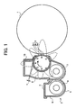
- FIG. 1 is a schematic drawing illustrating a construction of a developing device of an image forming apparatus according to the present invention.
- a photoconductive drum 1 as an image bearing member is rotatably driven by a driving device (not shown) when an image is formed.
- the photoconductive drum 1 is then uniformly charged by a charging device (not shown).
- a surface of the photoconductive drum 1 is exposed with a beam light emitted from an exposure device (e.g., a writing device) to form an electrostatic latent image thereon.
- an exposure device e.g., a writing device
- a developing device 2 develops the electrostatic latent image formed on the surface of the photoconductive drum 1 into a visible image with toner (i.e. , a toner image) .
- the toner image is transferred onto a transfer sheet, which is fed by a feeding device (not shown), by a transfer device (not shown).
- the toner image transferred onto the transfer sheet is fixed by a fixing device (not shown).
- the transfer sheet is then discharged to outside the apparatus.
- the photoconductive drum 1 is cleaned by a cleaning device (not shown) after the toner image has been transferred onto the transfer sheet.
- the above-described image forming operation is continuously repeated until the set number of prints is completed.
- a belt-type photoconductive element may be employed instead of the photoconductive drum 1.
- a developing roller 3 (i.e., a developer bearing member) is provided in a developer container 6 at a position opposed to the photoconductive element 1 through an inlet of the developer container 6.
- the developer container 6 includes an upper case 3 and a lower case 4. End portions of the developing rollers 3 are rotatably supported by end portions of the developer container 6.
- Conveying screws 7 and 8 i.e., an agitation device
- End portions of conveying screws 7 and 8 are rotatably supported by end portions of the developer containing 6.
- Conveying screws 7 and 8 are rotatably driven by a driving source (not shown). Conveying screws 7 and 8 circulate a developer (a two-component developer including toner and a magnetic carrier) in the developer container 6 while agitating the developer and conveying it to the developing roller 3.
- the developing roller 3 includes a magnet roller 3b and a developing sleeve 3c.
- the magnet roller 3b includes a plurality of magnets 3a inside.
- the developing sleeve 3c is provided outside of the magnet roller 3b to carry and convey a developer.
- the magnet roller 3b is fixedly provided.
- the developing sleeve 3c is rotatably driven by a driving source (not shown) in a direction indicated by an arrow in Fig. 1 , the developer adheres to a surface of the developer sleeve 3c by a magnetic force 9 of the plurality of magnets 3a to form a magnetic brush.
- the magnetic brush is supplied to a developing region formed between the photoconductive drum 1 and the developing sleeve 3c.
- a regulating member 10 (which is referred to as a doctor) is provided to a position above the circumferential surface of the developing sleeve 3c while creating a clearance "h" of a predetermined amount between the circumferential surface of the developing sleeve 3c and the regulating member 10.
- the regulating member 10 regulates an amount of the developer on the surface of the developer sleeve 3c so that an even amount of the developer is supplied to the developing region.
- the non-magnetic regulating member is employed to simplify a construction of the developing device 2, a magnetic regulating member or a regulating member including a non-magnetic regulating member and a magnetic board may be employed.
- an amount of a developer 11 i.e., magnetic brush
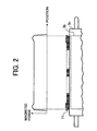
- an amount of a developer 11 is increased in the order of a location of the developer 11, namely, in the order of the developer 11 located close to ends the magnet roller 3b such that the amount of the developer 11 is largest in regions adjacent to the ends of the magnet roller 3b as illustrated in Fig. 2 .
- the above-described phenomenon occurs in relation to a line of magnetic force of the magnet 3a.
- the magnetic force is large at an edge of the magnet 3a when the magnetic force of the magnet 3a, positioned at immediate upstream side of the regulating member 10, in a direction of normal is observed.
- a relationship between the magnetic force and the amount of the developer on the surface of the developing sleeve 3c is described below. The relationship is identical to each magnet of the plurality of magnets 3a. Thus, the description is made based on the relationship between the magnetic force of one magnet and the amount of the developer on the surface of the developing sleeve 3c.
- Fig. 3A is a diagram illustrating the magnetic force 9 of the magnet 3a in the normal direction disposed in a central portion of the magnet roller 3b.
- Fig. 3B is a diagram illustrating the magnetic force 9 of the magnet 3a in the normal direction disposed in ends of the magnet roller 3b.
- Fig. 3C is a diagram illustrating the magnetic force 9 of the magnet 3a in the normal direction disposed in the central portion of the magnet roller 3b, and the developer 11 on the developing sleeve 3c.
- Fig. 3D is a diagram illustrating the magnetic force 9 of the magnet 3a in the normal direction disposed in the ends of the magnet roller 3b, and the developer 11 on the developing sleeve 3c.
- the magnetic force 9 of the magnet 3a in the normal direction disposed in ends of the magnet roller 3b differs from that of the magnet 3a in the normal direction disposed in the central portion of the magnet roller 3b.
- the larger the magnetic force 9 in the normal direction the larger the magnetic force 9 in a tangent line direction.
- the magnetic force 9 in the tangent line direction produces an effect of inclining the magnetic brush 11 toward a surface side of the developing sleeve 3c.
- An amount of a developer that passes the regulating member 10 is increased when the magnetic brush 11 passes the regulating member 10 while the magnetic brush 11 on the developing sleeve 3c is inclined toward the surface side of the developing sleeve 3c compared to a case where the magnetic brush 11 on the developing sleeve 3c passes the regulating member 10 in an upright posture.
- the magnetic force 9 in the normal direction at ends of the magnet roller 3b is larger than that in the central portion thereof due to an effect of a wraparound magnetic force.
- the magnetic force 9 in the tangent line direction at ends of the magnet roller 3b becomes larger than that in the central portion thereof. Because the magnetic force 9 in the tangent line direction has the effect of inclining the magnetic brush 11 toward the surface side of the developing sleeve 3c, an increased amount of a developer passes the regulating member 10 at ends of the magnet roller 3b compared to the amount of the developer that passes the regulating member 10 in the central portion of the magnet roller 3b, even if the clearance "h" between the developing sleeve 3c and the regulating member 10 is uniformly created in the direction of the length. Due to the above-described mechanism, the amount of the developer in end portions of the surface of the developing sleeve 3c is larger than that in the central portion thereof.
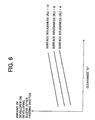
- FIG. 6 is a diagram illustrating a relationship among an amount of the clearance "h" between the regulating member 10 and the developing sleeve 3c, a degree of a surface roughness of the developing sleeve 3c, and an amount of the developer 11 adheres to the developing sleeve 3c.
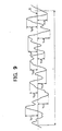
- Rz ten-point mean roughness
- JIS B0601 Japanese Industrial Standards
- the definition of Rz is the arithmetic mean of values of ten-point mean roughness measured at various parts chosen at random on a surface of an object.
- a method of obtaining ten-point mean roughness Rz is illustrated in Fig. 9 .
- a portion having a measurement length 1 is sampled from a waviness curve.
- the heights of the five highest peaks from the center line m i.e., Yp1, Yp2, Yp3, Yp4 and Yp5 are measured.
- the unit of Rz is ⁇ m.
- the amount of the developer 11 increases as the surface of the developing sleeve 3c is made rougher if the amount of the clearance "h" is the same.
- the amount of the developer 11 increases as the amount of the clearance "h” is increased if the degree of the surface roughness of the developing sleeve 3c is the same.
- a friction between the developing sleeve 3c and developer 11 is increased as the degree of the surface roughness of the developing sleeve 3c is increased.
- a force in which the developer 11 passes the regulating member 10 is increased as illustrated in Fig. 7A .
- the passing force of the developer 11 passing the regulating member 10 is decreased if the degree of the surface roughness of the developing sleeve 3c is decreased because the friction between the developing sleeve 3c and developer 11 is decreased as illustrated in Fig. 7B .
- An arrow in Figs. 7A and 7B indicates a moving direction of the developer 11.
- the amount of the developer 11 passing the regulating member 11 is increased if the degree of the surface roughness of the developing sleeve 3c is increased.
- the amount of the developer 11 passing the regulating member 10 is decreased if the degree of the surface roughness of the developing sleeve 3c is decreased.
- An amount of the developer 11 on the surface of the developing sleeve 3c corresponding to the vicinity of ends of the magnet roller 3b is decreased without imposing a stress on the developer 11 if a degree of a surface roughness of end portions of the developing sleeve 3c, which correspond to ends of the magnet roller 3b, is decreased compared to the degree of the surface roughness of the central portion thereof, which corresponds to a central portion of the magnet roller 3b, thereby preventing an occurrence of the above-described phenomenon.
- the surface roughness of end portions of the developing sleeve 3c i.e., "H2" which is outside of a position "P1" is decreased compared to that of the central portion thereof (i.e., "H1" which is inside of the position "P1") such that a transportation capacity of the developer 11 of end portions of the developing sleeve 3c is smaller than that of the central portion of the developing sleeve 3c.
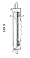
- the above-described effect is enhanced if the portion of "H2", in which the transportation capacity of a developer is made smaller, is extended to a position "P2" (see Fig. 8 ) which is outside of ends of the magnet roller 3b.
- a side sealing member is provided to ends of the developing roller 3 to cover end portions of the surface of the developing roller 3.
- the side sealing member is employed.
- the surface roughness of the portions of the developer roller 3, which are covered by the side sealing member i.e. , "H3" in Fig. 8
- the value of the surface roughness of the developer roller 3 that does not damage the side sealing member is equal to 4 ⁇ m or smaller.
- the surface roughness of the developing sleeve 3c between the central portion (i.e., "H1") and end portions (i.e., "H2") thereof changes in one stage.
- the surface roughness of the developing sleeve 3c changes in a multistage from end portions to the central portion of the developing sleeve 3c (i.e., the surface roughness changes continuously linearly between the position "P1" and a predetermined portion "P3") as illustrated in Fig. 8 , and a similar effect as that of the first example is produced.
Landscapes
- Physics & Mathematics (AREA)
- General Physics & Mathematics (AREA)
- Dry Development In Electrophotography (AREA)
- Magnetic Brush Developing In Electrophotography (AREA)
- Rolls And Other Rotary Bodies (AREA)
Claims (4)
- Dispositif de développement (2) ayant un récipient de révélateur (6) contenant un révélateur en deux composants comprenant du toner et un support, un rouleau de développement et un élément de régulation (10) pour réguler une quantité de révélateur (11) supportée par le rouleau de développement, le rouleau de développement comprenant ;un rouleau magnétique (3b) incluant une pluralité d'aimants (3a) configurés pour attirer le révélateur; etun manchon de développement (3c) placé à l'extérieur du rouleau magnétique et configurer pour porter et convoyer le révélateur tout en supportant le révélateur par une force magnétique du rouleau magnétique,dans lequel une partie centrale (H1) du manchon de développement a une première rugosité de surface et dans lequel une partie la plus extérieure (H3) qui correspond à l'extérieur des extrémités du rouleau magnétique a une seconde rugosité de surface qui est plus lisse que la première rugosité de surface ; caractérisé en ce que :des parties d'extrémité (H2) du manchon de développement qui correspondent à un voisinage des extrémités du rouleau magnétique ont une troisième rugosité de surface qui est plus petite que la première rugosité de surface mais plus grande que la seconde rugosité de surface, de telle manière qu'une capacité de transport du révélateur dans lesdites parties d'extrémité (H2) qui correspondent à un voisinage des extrémités du rouleau magnétique est plus petite que la capacité de transport du révélateur dans une partie centrale du manchon de développement (H1) qui correspond à une partie centrale du rouleau magnétique.
- Dispositif de développement selon la revendication 1, dans lequel un élément d'étanchéité est placé aux extrémités du manchon de développement et couvre les parties les plus extérieures de la surface du manchon de développement (H3), et dans lequel une valeur de la rugosité de surface (Rz) des parties les plus extérieures de la surface du manchon de développement qui sont couvertes par l'élément d'étanchéité est réglée égale à 4 µm ou moins.
- Dispositif de développement selon la revendication 1 ou 2, dans lequel la rugosité de surface de la partie centrale (H1) du manchon de développement (3c) est d'environ 12 µm et la rugosité de surface des parties d'extrémité (H2) du manchon de développement est d'environ 9 µm.
- Appareil de formation d'image, comprenant un dispositif de développement (2) selon l'une quelconque des revendications 1, 2 et 3.
Applications Claiming Priority (4)
| Application Number | Priority Date | Filing Date | Title |
|---|---|---|---|
| JP2000366614 | 2000-12-01 | ||
| JP2000366614 | 2000-12-01 | ||
| JP2001351536 | 2001-11-16 | ||
| JP2001351536A JP2002229336A (ja) | 2000-12-01 | 2001-11-16 | 現像ローラ、現像装置及び画像形成装置 |
Publications (3)
| Publication Number | Publication Date |
|---|---|
| EP1211571A2 EP1211571A2 (fr) | 2002-06-05 |
| EP1211571A3 EP1211571A3 (fr) | 2004-10-13 |
| EP1211571B1 true EP1211571B1 (fr) | 2008-06-25 |
Family
ID=26605048
Family Applications (1)
| Application Number | Title | Priority Date | Filing Date |
|---|---|---|---|
| EP01310062A Expired - Lifetime EP1211571B1 (fr) | 2000-12-01 | 2001-11-30 | Rouleau de développement avec un cylindre de développement transportant le développateur sans contrainte produite par un élément de régulation |
Country Status (4)
| Country | Link |
|---|---|
| US (1) | US6640076B2 (fr) |
| EP (1) | EP1211571B1 (fr) |
| JP (1) | JP2002229336A (fr) |
| DE (1) | DE60134526D1 (fr) |
Families Citing this family (15)
| Publication number | Priority date | Publication date | Assignee | Title |
|---|---|---|---|---|
| EP1431843A3 (fr) | 2002-08-30 | 2004-09-15 | Ricoh Company, Ltd. | Appareil de formation d'images sans dispositif de nettoyage et cartouche de traitement pour cet appareil |
| US7085528B2 (en) * | 2002-12-03 | 2006-08-01 | Ricoh Company, Ltd. | Cleaning unit, process cartridge, and image forming apparatus |
| JP4165817B2 (ja) * | 2003-04-10 | 2008-10-15 | 株式会社リコー | 画像形成装置及びこれに用いられるプロセスカートリッジ |
| JP2004334092A (ja) * | 2003-05-12 | 2004-11-25 | Ricoh Co Ltd | クリーニング装置、プロセスカートリッジ、画像形成装置、及びこれらに用いるトナー |
| JP2005017463A (ja) * | 2003-06-24 | 2005-01-20 | Ricoh Co Ltd | 画像形成装置及びこれに用いられるプロセスカートリッジ、トナー |
| JP4418192B2 (ja) * | 2003-08-20 | 2010-02-17 | 株式会社リコー | クリーニング装置、プロセスカートリッジ及び画像形成装置 |
| JP2005070274A (ja) * | 2003-08-22 | 2005-03-17 | Ricoh Co Ltd | 画像形成装置、プロセスカートリッジ、トナー |
| JP2005300626A (ja) * | 2004-04-07 | 2005-10-27 | Ricoh Co Ltd | クリーニング装置、画像形成装置 |
| DE602006015138D1 (de) * | 2005-09-13 | 2010-08-12 | Ricoh Kk | Entwicklungswalze und Vorrichtung zur Oberflächenbehandlung |
| JP2007298586A (ja) * | 2006-04-28 | 2007-11-15 | Kyocera Mita Corp | 現像装置及びこれを搭載した画像形成装置 |
| JP2008250121A (ja) * | 2007-03-30 | 2008-10-16 | Ricoh Co Ltd | 現像装置およびプロセスカートリッジおよび画像形成装置 |
| JP2008310253A (ja) * | 2007-06-18 | 2008-12-25 | Konica Minolta Business Technologies Inc | 一成分現像装置および該現像装置に使用される現像ローラ |
| US20110311267A1 (en) * | 2010-06-17 | 2011-12-22 | Toshiba Tec Kabushiki Kaisha | Developing device, image forming apparatus and method |
| JP5751959B2 (ja) * | 2011-07-05 | 2015-07-22 | キヤノン株式会社 | 現像装置 |
| JP6320169B2 (ja) | 2014-05-23 | 2018-05-09 | キヤノン株式会社 | 現像装置、プロセスカートリッジ及び画像形成装置 |
Family Cites Families (35)
| Publication number | Priority date | Publication date | Assignee | Title |
|---|---|---|---|---|
| US4380966A (en) * | 1980-10-11 | 1983-04-26 | Canon Kabushiki Kaisha | Development apparatus |
| JPS59193474A (ja) * | 1983-04-18 | 1984-11-02 | Hitachi Metals Ltd | 現像装置 |
| FR2597625B1 (fr) * | 1986-04-18 | 1992-02-14 | Ricoh Kk | Appareil pour developper une image electrostatique latente, notamment en electrocopie |
| JPS6398675A (ja) * | 1986-10-16 | 1988-04-30 | Toshiba Corp | 電子複写機の現像装置 |
| EP0314436B1 (fr) * | 1987-10-28 | 1993-12-29 | Canon Kabushiki Kaisha | Appareil de développement |
| US5177536A (en) * | 1989-03-31 | 1993-01-05 | Canon Kabushiki Kaisha | Developing apparatus having a magnetic seal |
| US5202729A (en) * | 1990-10-26 | 1993-04-13 | Canon Kabushiki Kaisha | Developing apparatus having a coated developing roller |
| DE4128942C2 (de) | 1991-01-16 | 1995-06-22 | Ricoh Kk | Entwicklungseinrichtung, welche in einer Bilderzeugungseinrichtung vorgesehen ist |
| JP3310685B2 (ja) | 1991-03-20 | 2002-08-05 | 株式会社リコー | 画像形成装置 |
| US5245391A (en) | 1991-04-01 | 1993-09-14 | Ricoh Company, Ltd. | Developing device having surface microfields for an image forming apparatus |
| US5220383A (en) | 1991-04-01 | 1993-06-15 | Ricoh Company, Ltd. | Developing device for an image forming apparatus having a large number of microfields formed on a developer carrier |
| JPH05216337A (ja) | 1991-07-31 | 1993-08-27 | Ricoh Co Ltd | 画像形成装置 |
| JP3243696B2 (ja) | 1991-11-14 | 2002-01-07 | 株式会社リコー | 現像装置 |
| JP2809934B2 (ja) * | 1992-06-17 | 1998-10-15 | 日立金属株式会社 | マグネットロールの処理方法 |
| US5384628A (en) | 1992-10-10 | 1995-01-24 | Ricoh Company, Ltd. | Developing device for image forming equipment |
| JP3305033B2 (ja) | 1993-02-26 | 2002-07-22 | 株式会社リコー | 現像装置 |
| US5508794A (en) | 1993-03-03 | 1996-04-16 | Ricoh Company, Ltd. | Developer recycling system and developer cartridge therefor |
| EP0619530B1 (fr) * | 1993-03-31 | 1999-11-03 | Canon Kabushiki Kaisha | Appareil de développement utilisant une lame élastique |
| US5347347A (en) * | 1993-05-25 | 1994-09-13 | Eastman Kodak Company | Apparatus for applying toner to an electrostatic image having improved developer flow |
| JP3413314B2 (ja) | 1994-10-21 | 2003-06-03 | 株式会社リコー | 画像形成装置 |
| JPH08179618A (ja) | 1994-12-21 | 1996-07-12 | Ricoh Co Ltd | 画像形成装置 |
| US6081378A (en) | 1995-04-24 | 2000-06-27 | Polycom, Inc. | High efficiency homogeneous polarization converter |
| JPH08305159A (ja) | 1995-04-28 | 1996-11-22 | Ricoh Co Ltd | 画像形成装置 |
| JPH08328376A (ja) * | 1995-06-01 | 1996-12-13 | Canon Inc | 画像形成装置用円筒部材およびその製造方法 |
| US5819145A (en) | 1995-07-31 | 1998-10-06 | Ricoh Company, Ltd. | Image forming device for forming a uniform toner layer on a developing roller |
| JP3605707B2 (ja) | 1995-10-11 | 2004-12-22 | 株式会社リコー | 画像形成装置 |
| JPH09146372A (ja) | 1995-11-24 | 1997-06-06 | Konica Corp | 現像装置 |
| JPH09265238A (ja) | 1996-03-28 | 1997-10-07 | Minolta Co Ltd | 現像装置 |
| JP3500008B2 (ja) | 1996-05-28 | 2004-02-23 | 株式会社リコー | 画像形成装置における現像能力検知方法 |
| JPH1026861A (ja) | 1996-07-10 | 1998-01-27 | Canon Inc | 多色画像形成装置 |
| JPH10254310A (ja) | 1996-11-29 | 1998-09-25 | Ricoh Co Ltd | 画像形成装置 |
| JP3440441B2 (ja) | 1996-12-19 | 2003-08-25 | 株式会社リコー | 画像形成装置 |
| JPH11316479A (ja) | 1997-12-09 | 1999-11-16 | Ricoh Co Ltd | 画像形成装置 |
| CN100507729C (zh) | 1998-04-20 | 2009-07-01 | 株式会社理光 | 图像形成装置及方法 |
| US6226481B1 (en) | 1998-12-07 | 2001-05-01 | Ricoh Company, Ltd. | Image forming apparatus with control over developing unit during an idle running of an intermediate image transfer body |
-
2001
- 2001-11-16 JP JP2001351536A patent/JP2002229336A/ja active Pending
- 2001-11-30 EP EP01310062A patent/EP1211571B1/fr not_active Expired - Lifetime
- 2001-11-30 DE DE60134526T patent/DE60134526D1/de not_active Expired - Lifetime
- 2001-12-03 US US09/998,316 patent/US6640076B2/en not_active Expired - Lifetime
Also Published As
| Publication number | Publication date |
|---|---|
| EP1211571A3 (fr) | 2004-10-13 |
| JP2002229336A (ja) | 2002-08-14 |
| DE60134526D1 (de) | 2008-08-07 |
| EP1211571A2 (fr) | 2002-06-05 |
| US6640076B2 (en) | 2003-10-28 |
| US20020067933A1 (en) | 2002-06-06 |
Similar Documents
| Publication | Publication Date | Title |
|---|---|---|
| EP1211571B1 (fr) | Rouleau de développement avec un cylindre de développement transportant le développateur sans contrainte produite par un élément de régulation | |
| EP1333338B1 (fr) | Porteur de révélateur avec des rainures superficielles, appareil de développement l'incorporant et dispositif de formation des images incorporant l'appareil de développement | |
| JP4070387B2 (ja) | 現像装置及び画像形成装置 | |
| EP1617297B1 (fr) | Procédé et appareil pour le développement d'image capables de former de manière efficace une couche d'agent de développement régulière | |
| US5625440A (en) | Developing device having seals between a toner transport roller and the toner hopper which prevent toner leakage and scattering | |
| EP2653929B1 (fr) | Dispositif de développement et appareil de formation d'images électrophotographiques l'incluant | |
| JP5403988B2 (ja) | 現像装置 | |
| EP1467261B1 (fr) | Appareil de formation d'image pour éviter la détérioration d'image par des brosses conductives tombées et la diffusion du révélateur | |
| US6829452B2 (en) | Image forming apparatus and developing device | |
| JP7459964B2 (ja) | トナー搬送装置およびそれを備えたクリーニング装置並びに画像形成装置 | |
| JPH1144997A (ja) | 現像装置 | |
| JP2000181221A (ja) | 画像形成装置 | |
| JPH1138855A (ja) | 画像形成装置用のクリーニング装置 | |
| KR100690102B1 (ko) | 현상 장치, 이 현상 장치를 이용하는 프로세스 카트리지 및화상 형성 장치 | |
| JP6509412B2 (ja) | 現像装置 | |
| JP3302474B2 (ja) | 現像装置 | |
| JP7826027B2 (ja) | 現像装置 | |
| JP3576769B2 (ja) | 画像形成装置 | |
| JP4355527B2 (ja) | 現像装置 | |
| JP7467931B2 (ja) | 画像形成装置 | |
| JP2000206788A (ja) | 現像装置 | |
| JP2009198895A (ja) | 潤滑剤塗布量制御装置、潤滑剤塗布量制御方法及び画像形成装置 | |
| JP2005077538A (ja) | 現像装置 | |
| JPH0764361A (ja) | 電子写真装置 | |
| JP2023055328A (ja) | クリーニングブレードおよび画像形成装置 |
Legal Events
| Date | Code | Title | Description |
|---|---|---|---|
| PUAI | Public reference made under article 153(3) epc to a published international application that has entered the european phase |
Free format text: ORIGINAL CODE: 0009012 |
|
| AK | Designated contracting states |
Kind code of ref document: A2 Designated state(s): AT BE CH CY DE DK ES FI FR GB GR IE IT LI LU MC NL PT SE TR |
|
| AX | Request for extension of the european patent |
Free format text: AL;LT;LV;MK;RO;SI |
|
| PUAL | Search report despatched |
Free format text: ORIGINAL CODE: 0009013 |
|
| AK | Designated contracting states |
Kind code of ref document: A3 Designated state(s): AT BE CH CY DE DK ES FI FR GB GR IE IT LI LU MC NL PT SE TR |
|
| AX | Request for extension of the european patent |
Extension state: AL LT LV MK RO SI |
|
| 17P | Request for examination filed |
Effective date: 20050120 |
|
| AKX | Designation fees paid |
Designated state(s): DE FR GB |
|
| 17Q | First examination report despatched |
Effective date: 20060628 |
|
| GRAP | Despatch of communication of intention to grant a patent |
Free format text: ORIGINAL CODE: EPIDOSNIGR1 |
|
| GRAS | Grant fee paid |
Free format text: ORIGINAL CODE: EPIDOSNIGR3 |
|
| GRAA | (expected) grant |
Free format text: ORIGINAL CODE: 0009210 |
|
| AK | Designated contracting states |
Kind code of ref document: B1 Designated state(s): DE FR GB |
|
| REG | Reference to a national code |
Ref country code: GB Ref legal event code: FG4D |
|
| REF | Corresponds to: |
Ref document number: 60134526 Country of ref document: DE Date of ref document: 20080807 Kind code of ref document: P |
|
| PLBE | No opposition filed within time limit |
Free format text: ORIGINAL CODE: 0009261 |
|
| STAA | Information on the status of an ep patent application or granted ep patent |
Free format text: STATUS: NO OPPOSITION FILED WITHIN TIME LIMIT |
|
| 26N | No opposition filed |
Effective date: 20090326 |
|
| REG | Reference to a national code |
Ref country code: FR Ref legal event code: PLFP Year of fee payment: 15 |
|
| REG | Reference to a national code |
Ref country code: FR Ref legal event code: PLFP Year of fee payment: 16 |
|
| PGFP | Annual fee paid to national office [announced via postgrant information from national office to epo] |
Ref country code: GB Payment date: 20161122 Year of fee payment: 16 Ref country code: FR Payment date: 20161118 Year of fee payment: 16 |
|
| PGFP | Annual fee paid to national office [announced via postgrant information from national office to epo] |
Ref country code: DE Payment date: 20171121 Year of fee payment: 17 |
|
| GBPC | Gb: european patent ceased through non-payment of renewal fee |
Effective date: 20171130 |
|
| REG | Reference to a national code |
Ref country code: FR Ref legal event code: ST Effective date: 20180731 |
|
| PG25 | Lapsed in a contracting state [announced via postgrant information from national office to epo] |
Ref country code: FR Free format text: LAPSE BECAUSE OF NON-PAYMENT OF DUE FEES Effective date: 20171130 |
|
| PG25 | Lapsed in a contracting state [announced via postgrant information from national office to epo] |
Ref country code: GB Free format text: LAPSE BECAUSE OF NON-PAYMENT OF DUE FEES Effective date: 20171130 |
|
| REG | Reference to a national code |
Ref country code: DE Ref legal event code: R119 Ref document number: 60134526 Country of ref document: DE |
|
| PG25 | Lapsed in a contracting state [announced via postgrant information from national office to epo] |
Ref country code: DE Free format text: LAPSE BECAUSE OF NON-PAYMENT OF DUE FEES Effective date: 20190601 |