EP1212964A2 - Stapelvorrichtung für CD Behältern - Google Patents
Stapelvorrichtung für CD Behältern Download PDFInfo
- Publication number
- EP1212964A2 EP1212964A2 EP01403091A EP01403091A EP1212964A2 EP 1212964 A2 EP1212964 A2 EP 1212964A2 EP 01403091 A EP01403091 A EP 01403091A EP 01403091 A EP01403091 A EP 01403091A EP 1212964 A2 EP1212964 A2 EP 1212964A2
- Authority
- EP
- European Patent Office
- Prior art keywords
- rack elements
- stacking device
- compartments
- rack
- case
- Prior art date
- Legal status (The legal status is an assumption and is not a legal conclusion. Google has not performed a legal analysis and makes no representation as to the accuracy of the status listed.)
- Withdrawn
Links
- 238000003780 insertion Methods 0.000 description 7
- 230000037431 insertion Effects 0.000 description 7
- 239000000463 material Substances 0.000 description 7
- 230000002093 peripheral effect Effects 0.000 description 5
- 239000004033 plastic Substances 0.000 description 5
- 229920003023 plastic Polymers 0.000 description 5
- 238000010276 construction Methods 0.000 description 3
- 239000002023 wood Substances 0.000 description 2
- 238000004519 manufacturing process Methods 0.000 description 1
Images










Classifications
-
- G—PHYSICS
- G11—INFORMATION STORAGE
- G11B—INFORMATION STORAGE BASED ON RELATIVE MOVEMENT BETWEEN RECORD CARRIER AND TRANSDUCER
- G11B33/00—Constructional parts, details or accessories not provided for in the other groups of this subclass
- G11B33/02—Cabinets; Cases; Stands; Disposition of apparatus therein or thereon
- G11B33/04—Cabinets; Cases; Stands; Disposition of apparatus therein or thereon modified to store record carriers
- G11B33/0405—Cabinets; Cases; Stands; Disposition of apparatus therein or thereon modified to store record carriers for storing discs
- G11B33/0461—Disc storage racks
- G11B33/0466—Disc storage racks for disc cartridges
-
- G—PHYSICS
- G11—INFORMATION STORAGE
- G11B—INFORMATION STORAGE BASED ON RELATIVE MOVEMENT BETWEEN RECORD CARRIER AND TRANSDUCER
- G11B33/00—Constructional parts, details or accessories not provided for in the other groups of this subclass
- G11B33/02—Cabinets; Cases; Stands; Disposition of apparatus therein or thereon
- G11B33/04—Cabinets; Cases; Stands; Disposition of apparatus therein or thereon modified to store record carriers
- G11B33/0405—Cabinets; Cases; Stands; Disposition of apparatus therein or thereon modified to store record carriers for storing discs
- G11B33/0461—Disc storage racks
- G11B33/0483—Disc storage racks for single disc boxes
Definitions
- the invention is based on the object of devising a stacking device of the above-mentioned type, which makes it possible for CD cases to be inserted into the compartments from a plurality of sides.
- a stacking device for CD cases or the like with three rack elements which in relation to the basic contour are arranged in the form of an equilateral triangle, in each case at a vertex, and between which there is provided a plurality of horizontal compartments which are respectively arranged one above the other and at a distance apart, wherein the lateral spacing between two respective rack elements which are adjacent in the direction of a base line is slightly larger than the width of a CD case to be inserted into a compartment.
- a tower-like stacking device of this type has the advantage that CD cases can be inserted from any side. The access to adjacent CD cases is facilitated if the CD cases are inserted respectively into successive compartments in each instance from a different side of the triangular basic contour. However, this also offers the possibility of coordinated stacking, in which a specific subject range is allocated to each insertion side.
- each of the rack elements prefferably be formed in one piece.
- the rack elements may be of rod-like design, for example produced from wood, or may also be tubular produced from plastics material.
- compartment block which is connected to the rack elements.
- This development offers a simplification in manufacture, since the compartment block, for example consisting of plastics material, can be injection-moulded as one part which is then securely connected to the three rack elements.
- each of the rack elements is assembled from a plurality of component parts, wherein at least one compartment is connected by adhesion or cohesion in each case to three rack elements associated with the vertices.
- individual compartments or also one or more compartment blocks are produced by adhesion or cohesion, for example as injection-moulded components from plastics material, which are then assembled one above the other to form a stacking element.
- This embodiment also offers the possibility of producing, within a predetermined grid, stacking elements of different height by a simple plug-and-socket connection.
- the rack elements can be securely joined together via a base plate and/or via a top member.
- the base plate can be produced from a different heavy material so that the stacking device is imparted a certain degree of basic stability by the base plate and is protected from tipping.
- the rack elements are of lamellar design and they extend respectively along the base lines forming an equilateral triangle, wherein the compartments are formed by slots in the interconnected lamellar rack elements.
- the width of the slots in horizontal direction is slightly larger than the width of the CD cases to be inserted, whereas the height of the slots in vertical direction is slightly larger than the thickness of the CD cases to be inserted.
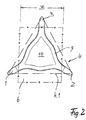
- Fig. 1 for a column-like or tower-like stacking device for CD cases essentially comprises three rack elements 1,2 and 3 which, as is evident from Fig. 2, - in relation to a basic contour 4 in the form of an equilateral triangle - are arranged respectively at the vertices of the triangle. Between the three rack elements 1,2 and 3 there is provided a plurality of horizontal compartments 5 which in each case are arranged parallel one above the other and at a distance apart. The lateral distance between two rack elements 1,2 and 2,3 and 3, 1 respectively which are adjacent in the direction of a base line is, as is evident from Fig. 2, slightly larger than the width B of a CD case 6 to be inserted into a compartment.
- each rack element adjacent one another on a base line for example the rack elements 1 and 2
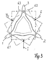
- the rack element 3 then serves as a limiting stop member for the CD case 6. It is thereby possible to insert a CD case from each side into each compartment. This is shown in plan view in Fig. 3 for illustrative purposes.
- the individual CD cases 6.1, 6.2, 6.3 can [sic] be inserted from each side of a base line 4.1 into a compartment of the stacking device.
- the rack elements 1,2 and 3 can be made in one piece, for example from wood, and can be securely connected to one another via a base member 7, which is of frame-like design in Fig. 1, but can also be in the form of a plate, as shown in Fig. 10, and also via a corresponding top member 8.
- the individual lamellar compartments are then secured, for example, in slots in the rack elements 1,2 and 3.
- the rack elements In a similar manner it is also possible for the rack elements to be produced individually in tubular form from a plastics material with corresponding insertion slots, and in a similar manner for the compartments to be of lamellar design with corresponding projections in the corner zones, which can be inserted into the insertion slots of the rack element.
- the three rack elements 1,2 and 3 are then rigidly joined together via a pushed-on base member 7 and a pushed-on base [sic] member 8.
- the compartments can in this case take the form of continuous plates or else, as shown in Fig. 2, they can be of frame-like design with a web 9 defining the peripheral contour, which encloses a free space 10.
- Fig. 3 shows in plan view the possibility of insertion for CD cases 6 which are then inserted one above the other in each case from a different side, as indicated by the arrows I,II and II.
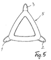
- Figs. 4,5 illustrate an embodiment which corresponds in its construction to the embodiment according to Figs, 1,2 but which visually is of substantially triangular configuration with outwardly bulging contour.
- the device can be assembled from a plurality of component parts.
- Figs. 6, 7 corresponds in its construction to the embodiment according to Figs, 1,2.
- the difference merely lies in the fact that the stacking device is generally of rather cylindrical appearance over the peripheral contour of the compartments 5.
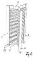
- Figs. 8,9 again corresponds in its basic construction to the embodiment according to Figs. 1,2.
- the compartments are formed by star-shaped flat webs 5,1 so that the stacking device is generally of star-shaped appearance.
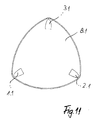
- Figs. 10 and 11 show an embodiment in which the base member 7.1 is in the form of a plate and the top member 8.1 is also plate-like and joins together the rack elements 1.1, 2.1 and 3.1.
- the special advantage of this embodiment lies in the fact that at least the base member 7.1 can be produced from a material of relatively high inherent weight, thereby imparting relatively high stability to the stacking device.
- each of the described embodiments can be provided in each case with a correspondingly formed plate-like base member 7.1 and/or a top member 8,1.
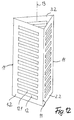
- Fig. 12 illustrates an embodiment in which the rack elements 1.2,2.2 and 3.2 are each of lamellar design and are joined together in the vicinity of their lateral edges 11 so that the surface regions extend approximately along the base line 4.
- the individual rack elements are provided with slots 12 which are delimited by webs 12.1 and which form the compartments.
- a CD case can be inserted from each side.
- the lamellar rack elements 1.1, 2.1 and 3.1 do not, as shown here, have to be flat but can be inwardly or outwardly curved in relation to the vertical centre axis 13.
- the lateral edges 11 can extend at a distance apart and be securely connected to one another via transverse webs.
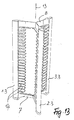
- Fig. 13 illustrates a variant of the embodiment according to Fig. 8.
- the rack elements 1.3, 2.3, 3.3 are each securely joined together with a base member 7 and a top member 8.
- the compartments are in this case not formed by planar or frame-like parts which extend respectively up to the adjacent rack element.
- the compartments are each formed by web-like lugs 14 on the individual racks, which each point towards the centre axis 13.
- Each rack element is thus of comb-like structure.
- Stacking devices of this type can be provided in each case in the vicinity of the base member and/or in the vicinity of the top member with recesses and/or projections so that a plurality of such stacking devices can be arranged tower-like one above the other by means of a plug-and-socket connection.
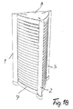
- the frame-like compartments 5 are of approximately triangular ground plan contour in which, however, the peripheral contour extends inwardly curved between the rack elements 1,2 and 3. As is illustrated in Fig. 15, the compartments 5 are frame-like with a free space 10. However, it is also possible for the compartments to be of correspondingly lamellar form.
- the peripheral contour of the boundary plate 8.2 is in this case identical to the peripheral contour of the compartments 5.
Landscapes
- Packaging For Recording Disks (AREA)
- Packaging Of Annular Or Rod-Shaped Articles, Wearing Apparel, Cassettes, Or The Like (AREA)
- Assembled Shelves (AREA)
Applications Claiming Priority (2)
| Application Number | Priority Date | Filing Date | Title |
|---|---|---|---|
| DE20020387U DE20020387U1 (de) | 2000-12-01 | 2000-12-01 | Ablageeinrichtung für CD-Kassetten |
| DE20020387U | 2000-12-01 |
Publications (2)
| Publication Number | Publication Date |
|---|---|
| EP1212964A2 true EP1212964A2 (de) | 2002-06-12 |
| EP1212964A3 EP1212964A3 (de) | 2003-01-02 |
Family
ID=7949523
Family Applications (1)
| Application Number | Title | Priority Date | Filing Date |
|---|---|---|---|
| EP01403091A Withdrawn EP1212964A3 (de) | 2000-12-01 | 2001-11-30 | Stapelvorrichtung für CD Behältern |
Country Status (7)
| Country | Link |
|---|---|
| US (2) | US20020066705A1 (de) |
| EP (1) | EP1212964A3 (de) |
| JP (2) | JP2002264983A (de) |
| CN (1) | CN2522981Y (de) |
| DE (1) | DE20020387U1 (de) |
| GB (1) | GB2370493A (de) |
| HK (1) | HK1048225A2 (de) |
Families Citing this family (9)
| Publication number | Priority date | Publication date | Assignee | Title |
|---|---|---|---|---|
| JP2852892B2 (ja) | 1995-12-29 | 1999-02-03 | テイ・エス テック株式会社 | 自動車用シート |
| JP3449327B2 (ja) | 1999-12-16 | 2003-09-22 | トヨタ車体株式会社 | 車両用シート |
| TWI224806B (en) * | 2000-05-12 | 2004-12-01 | Semiconductor Energy Lab | Semiconductor device and manufacturing method thereof |
| DE20020387U1 (de) * | 2000-12-01 | 2001-03-01 | Sunhing Millennium Ltd., Kowloon | Ablageeinrichtung für CD-Kassetten |
| US6536608B2 (en) * | 2001-07-12 | 2003-03-25 | Saint-Gobain Ceramics & Plastics, Inc. | Single cast vertical wafer boat with a Y shaped column rack |
| US7051899B1 (en) * | 2003-09-25 | 2006-05-30 | Keith Offenhauer | Carousel-type holder for dispensers for tape marker flags and POST-IT stacks |
| USD500418S1 (en) * | 2003-10-07 | 2005-01-04 | Cometform Ltd. | Display equipment for sales and advertising |
| HK1084828A2 (en) * | 2006-05-26 | 2006-08-04 | 凌思设计有限公司 | Multipurpose stereoscopic display shelf |
| US8708165B2 (en) * | 2011-01-03 | 2014-04-29 | John M. Weiher | Apparatus configured to store media cases and boxes |
Family Cites Families (26)
| Publication number | Priority date | Publication date | Assignee | Title |
|---|---|---|---|---|
| USD311102S (en) * | 1986-12-05 | 1990-10-09 | Philip Morris Incorporated | Merchandising display stand or the like |
| US5188240A (en) * | 1991-07-05 | 1993-02-23 | Robert K. Hanson | Storage unit for recording-media boxes |
| GB2267381A (en) * | 1992-04-29 | 1993-12-01 | Tin Horse Design Limited | Compact disk rack |
| FR2692120B1 (fr) * | 1992-06-15 | 1994-09-23 | Ecole Nat Sup Creation Ind | Système modulaire de rangement. |
| USD352848S (en) * | 1992-09-02 | 1994-11-29 | Shahriar Dardashti | Storage rack |
| DE4303698A1 (en) * | 1993-02-09 | 1993-09-02 | Frank Mueller | Frame for storing CD, music and video cassettes - has side wall parts gripping stored objects at least at their diagonal ends |
| US5314077A (en) * | 1993-02-18 | 1994-05-24 | Theosabrata Yos S | Storage rack |
| US5341943A (en) * | 1993-04-06 | 1994-08-30 | Fraser Richard J | Decorative stand for compact discs |
| GB2276808A (en) * | 1993-04-08 | 1994-10-12 | Stephen Paul Joseph Astruc | Collapsible storage rack for entertainments media |
| USD364979S (en) * | 1993-10-15 | 1995-12-12 | Thomas Brian D | Cap and hat rack |
| JPH09168441A (ja) * | 1995-12-21 | 1997-06-30 | Elecom Kk | ラック |
| US5908121A (en) * | 1996-03-11 | 1999-06-01 | Dardashti; Shahriar | Adjustable display assembly |
| USD380925S (en) * | 1996-05-28 | 1997-07-15 | Abel Chu | Rack for compact disks |
| TW298337U (en) * | 1996-08-19 | 1997-02-11 | guo-min Gao | Tilting-type stackable CD rack |
| GB2317327B (en) * | 1996-09-24 | 1998-08-05 | Kao Kuo Ming | An inclined type stackable CD rack |
| FR2754379B1 (fr) * | 1996-10-07 | 1998-12-11 | Azema Laurent | Ensemble modulable pour le rangement d'articles sensiblement plats, notamment de disques compacts |
| US6039186A (en) * | 1997-04-16 | 2000-03-21 | Fluoroware, Inc. | Composite transport carrier |
| NL1006008C2 (nl) * | 1997-05-07 | 1998-11-10 | Zedek Bv | Plano uit karton geschikt voor het vormen van een CD-rek. |
| USD397561S (en) * | 1997-06-03 | 1998-09-01 | Spectra Products Corporation | Freestanding modular display/divider wall |
| US5984115A (en) * | 1998-03-06 | 1999-11-16 | Koestenblatt; Erik D. | Compact disc case system |
| US6126020A (en) * | 1999-01-06 | 2000-10-03 | Sunhing Millennium Limited | Assemblable storage and display unit |
| USD435189S (en) * | 1999-08-19 | 2000-12-19 | Sunhing Millennium Limited | Storage rack for holding articles |
| USD453654S1 (en) * | 2000-05-18 | 2002-02-19 | Kwok's Brother Manufacturing Limited | Rack for compact disks |
| USD441246S1 (en) * | 2000-05-31 | 2001-05-01 | Sunhing Millennium Limited | Storage rack |
| DE20020387U1 (de) * | 2000-12-01 | 2001-03-01 | Sunhing Millennium Ltd., Kowloon | Ablageeinrichtung für CD-Kassetten |
| US6536608B2 (en) * | 2001-07-12 | 2003-03-25 | Saint-Gobain Ceramics & Plastics, Inc. | Single cast vertical wafer boat with a Y shaped column rack |
-
2000
- 2000-12-01 DE DE20020387U patent/DE20020387U1/de not_active Expired - Lifetime
-
2001
- 2001-11-30 CN CN01269660U patent/CN2522981Y/zh not_active Expired - Fee Related
- 2001-11-30 HK HK01108447A patent/HK1048225A2/xx not_active IP Right Cessation
- 2001-11-30 EP EP01403091A patent/EP1212964A3/de not_active Withdrawn
- 2001-11-30 JP JP2001367337A patent/JP2002264983A/ja active Pending
- 2001-11-30 GB GB0128757A patent/GB2370493A/en not_active Withdrawn
- 2001-11-30 US US09/996,785 patent/US20020066705A1/en not_active Abandoned
-
2003
- 2003-03-04 US US10/377,747 patent/US20040074853A1/en not_active Abandoned
-
2004
- 2004-07-12 JP JP2004004107U patent/JP3107235U/ja not_active Expired - Lifetime
Also Published As
| Publication number | Publication date |
|---|---|
| CN2522981Y (zh) | 2002-11-27 |
| US20040074853A1 (en) | 2004-04-22 |
| HK1048225A2 (en) | 2003-03-07 |
| DE20020387U1 (de) | 2001-03-01 |
| JP2002264983A (ja) | 2002-09-18 |
| EP1212964A3 (de) | 2003-01-02 |
| JP3107235U (ja) | 2005-01-27 |
| US20020066705A1 (en) | 2002-06-06 |
| GB2370493A (en) | 2002-07-03 |
| GB0128757D0 (en) | 2002-01-23 |
Similar Documents
| Publication | Publication Date | Title |
|---|---|---|
| US4932538A (en) | Fixture support wall panel | |
| US6761609B1 (en) | Toy building set with flexible toy building sheet element | |
| EP0359894B1 (de) | Sechsweg-Verbinder | |
| US6116436A (en) | Modular shelving storage system | |
| EP0324232A2 (de) | Lautsprechergehäuse | |
| EP1212964A2 (de) | Stapelvorrichtung für CD Behältern | |
| WO1999013953A1 (en) | A thermoformed toy building plate | |
| US10238208B2 (en) | Modular food product display stand | |
| US5845790A (en) | Apparatus and related method for interconnecting articles | |
| GB2204566A (en) | Containers | |
| WO2007030871A1 (en) | Modular storage system | |
| US6789686B2 (en) | Rack with divided base plate for stacking flat articles | |
| CN211767078U (zh) | 一种冷却风机周转包装托盘 | |
| US20080087617A1 (en) | Cake tier separator for layered cakes | |
| US5655460A (en) | Interconnectible spacers for supporting an article from a base surface | |
| US11696640B2 (en) | Shelving system | |
| JP2000270937A (ja) | 新聞および雑誌収納棚 | |
| JPS6110502Y2 (de) | ||
| RU2231277C1 (ru) | Полка | |
| WO1992016081A1 (en) | Loudspeaker enclosure | |
| JP2004223227A (ja) | 棚装置 | |
| JP3022089U (ja) | 思うまま本棚等 | |
| AU2006292022B2 (en) | Modular storage system | |
| GB2293594A (en) | Panels for building containers | |
| JPH0630831A (ja) | 長方形板状物体の展示棚 |
Legal Events
| Date | Code | Title | Description |
|---|---|---|---|
| PUAI | Public reference made under article 153(3) epc to a published international application that has entered the european phase |
Free format text: ORIGINAL CODE: 0009012 |
|
| AK | Designated contracting states |
Kind code of ref document: A2 Designated state(s): AT BE CH CY DE DK ES FI FR GB GR IE IT LI LU MC NL PT SE TR |
|
| AX | Request for extension of the european patent |
Free format text: AL;LT;LV;MK;RO;SI |
|
| PUAL | Search report despatched |
Free format text: ORIGINAL CODE: 0009013 |
|
| AK | Designated contracting states |
Kind code of ref document: A3 Designated state(s): AT BE CH CY DE DK ES FI FR GB GR IE IT LI LU MC NL PT SE TR |
|
| AX | Request for extension of the european patent |
Free format text: AL;LT;LV;MK;RO;SI |
|
| 17P | Request for examination filed |
Effective date: 20021121 |
|
| 17Q | First examination report despatched |
Effective date: 20030207 |
|
| AKX | Designation fees paid | ||
| REG | Reference to a national code |
Ref country code: DE Ref legal event code: 8566 |
|
| STAA | Information on the status of an ep patent application or granted ep patent |
Free format text: STATUS: THE APPLICATION IS DEEMED TO BE WITHDRAWN |
|
| 18D | Application deemed to be withdrawn |
Effective date: 20030702 |