EP1212965A1 - Chaise - Google Patents
Chaise Download PDFInfo
- Publication number
- EP1212965A1 EP1212965A1 EP01125697A EP01125697A EP1212965A1 EP 1212965 A1 EP1212965 A1 EP 1212965A1 EP 01125697 A EP01125697 A EP 01125697A EP 01125697 A EP01125697 A EP 01125697A EP 1212965 A1 EP1212965 A1 EP 1212965A1
- Authority
- EP
- European Patent Office
- Prior art keywords
- rods
- locking part
- receptacles
- parallel rods
- parallel
- Prior art date
- Legal status (The legal status is an assumption and is not a legal conclusion. Google has not performed a legal analysis and makes no representation as to the accuracy of the status listed.)
- Withdrawn
Links
Images



Classifications
-
- A—HUMAN NECESSITIES
- A47—FURNITURE; DOMESTIC ARTICLES OR APPLIANCES; COFFEE MILLS; SPICE MILLS; SUCTION CLEANERS IN GENERAL
- A47C—CHAIRS; SOFAS; BEDS
- A47C9/00—Stools for specified purposes
- A47C9/02—Office stools; Workshop stools
- A47C9/025—Stools for standing or leaning against, e.g. in a semi-standing or half-seated position
-
- A—HUMAN NECESSITIES
- A47—FURNITURE; DOMESTIC ARTICLES OR APPLIANCES; COFFEE MILLS; SPICE MILLS; SUCTION CLEANERS IN GENERAL
- A47C—CHAIRS; SOFAS; BEDS
- A47C5/00—Chairs of special materials
- A47C5/04—Metal chairs, e.g. tubular
- A47C5/10—Tubular chairs of foldable, collapsible, or dismountable type
Definitions
- the present invention relates to a chair with a along two first ones running parallel to each other Poles adjustable in height, with which the Poles in the lower end area over support legs on the Support the ground using these first parallel rods with a pair of second parallel rods around one horizontal axis, which is below the seat, swiveling are connected so that the chair from the use position with spread pairs of rods in a flat Transport position is foldable, being in the Use position with spread pairs of rods one Lock is provided.
- a chair of the type mentioned at the beginning is for example known from DE 197 33 785 A1.
- the chair serves as a lock in the erected position Use position with spread pairs of rods one Cross strut made of a round material, which in the Use position as a stop for one of the pairs of rods serves.
- This simple previously known solution is at best met a stop function, but is not suitable as an effective one Abutment to support the second pair of rods acting forces. In particular, these forces act in disadvantageously mainly on the one serving as a stop Aim.
- the Rod pairs when folded into the transport position not prevented.
- the object of the present invention is therefore in creating a lock in the joint area that a more even flow of force in both pairs of rods guaranteed and in addition to the pure stop function other functions fulfilled.
- a locking part is used for locking, which is arranged in the joint area and in each case recordings for the has first parallel rods and a support area to support an arch area that supports the second pair connecting parallel rods.
- Locking part according to the invention are by the recordings the parallel rods of the first pair of rods at least partially bordered so that the forces at the Weight load of the chair over a greater length of the Poles are introduced into this and not punctually as with an adjacent strut according to the prior art. Also the forces that act on the second pair of rods will picked up by the locking part over the Support area on which the arch area is supported, the the second pair of parallel bars above each other combines.
- the locking part according to one Further development of the invention also includes recordings for the second parallel bars, each further inside next to the mounts for the first parallel bars and the second parallel bars in the folded one Can take up transport position.
- the Locking part on a support area.
- the Locking part is preferably a molded plastic part.
- said support area preferably has one on the the recordings for the parallel bars protruding support nose or opposite side like. This can then be used for this support nose Arch area, which is the second pair of parallel rods above connects with each other, in the spread position support.
- the Invention provided that on the locking part on the Side on which the receptacles for the pairs of rods are are, at least one element is molded, which the Push the spread pairs of rods together in the Prevents use position, d. that is, the pairs of rods in the spread use position holds.
- Such one molded element can, for example, at least one Stop lens.
- the locking part is arranged in the joint area.
- the two pairs of rods when opening the chair into the spread use position are pivotable across the Arresting.
- the locking part preferably each in the mounts for the first parallel bars and / or in the inner recordings for the second parallel rods each have holes that extend across take up the locking part extending hinge axis.
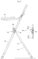
- FIGS. 1 and 2 show a chair according to the invention with a along two first ones running parallel to each other Poles 103, 104 height-adjustable seat 99.
- the Device for the height adjustment of the seat 99 and its Locking at an appropriate altitude is not Subject of the present invention and is therefore not explained in detail below.
- the chair according to the invention is like the side view according to Figure 2 shows set up, the in the use position Rod pairs consisting of the first two parallel ones Rods 103, 104, which are a little further out and which are extend further up and the second parallel Bars 106, 107 are spread. From Figure 2 you can do well recognize that the second pair of each further inside lying parallel rods 106, 107 (see also FIG. 1) is shorter and in this spread use position the first pair of rods 103, 104 at an acute angle occupies. The first two parallel rods 103, 104 both extend upwards and at these is above of the joint 98, the seat 99 is fastened in a height-adjustable manner.
- the chair can be folded into a flat transport position in which both pairs of rods, namely the first Bars 103, 104 and the second bars 106, 107 approximately parallel, d. that is, they are relatively close together. That in the Side view according to FIG. 2 recognizable locking part 100 has the task of creating an arch region 108 (see FIG. 1) which the second pair of parallel rods 106, 107 above each other connects, in the spread use position according to FIG. 2 support.
- FIG. 2 A section of the folded position is shown in FIG. 2 shown separately on the right, so that the course of the Rods then recognizes.
- Figure 3 shows in principle a top view of the Locking part 100 from which the support area 105 can recognize, which serves the previously mentioned Arc region 108 of the second pair of parallel rods 106, 107 to support.
- This arch area 108 overflows one corresponding to the pipe diameter of the bend area shaped and dimensioned trough-shaped depression 120 the top of the support area 105, which one in the Side view of the locking part 100 according to FIG. 6 can recognize.
- the two images can be seen in FIG 101, 102 for the two rods 103, 104 of the first Rod pair. You can also see that the locking part 100 in FIG.
- Receptacles 109, 110 are more parallel for the second pair Bars 106, 107, which have a partial circular shape and the Partially include rods 106, 107. They also have two outer receptacles 101, 102 at least in sections a partial circle or partial ring shape so that they are the outer partially enclose parallel rods 103, 104.
- the second pair runs in parallel Rods 106, 107 connecting arch area 108 over the am best trough-shaped depression 120 recognizable in FIG. 6 on the upper side on the support area 105 shown transport position, however, in which the second Pair of parallel rods 106, 107 only a small angle the pair of first parallel rods 103, 104 and almost lying parallel with these are the two inner rods 106, 107 of the second pair of the two inner images 109, 110 of the locking part 100 added.
- FIG. 8 shows that approximately in the axis of the bores 115, 116 also in the formations on which the holding lenses 111, 112 are located, corresponding bores 121, 122 for the Inclusion of a transverse joint axis are present.
Landscapes
- Purses, Travelling Bags, Baskets, Or Suitcases (AREA)
- Special Chairs (AREA)
Applications Claiming Priority (2)
| Application Number | Priority Date | Filing Date | Title |
|---|---|---|---|
| DE10061396 | 2000-12-09 | ||
| DE2000161396 DE10061396B4 (de) | 2000-12-09 | 2000-12-09 | Stuhl |
Publications (1)
| Publication Number | Publication Date |
|---|---|
| EP1212965A1 true EP1212965A1 (fr) | 2002-06-12 |
Family
ID=7666496
Family Applications (1)
| Application Number | Title | Priority Date | Filing Date |
|---|---|---|---|
| EP01125697A Withdrawn EP1212965A1 (fr) | 2000-12-09 | 2001-10-27 | Chaise |
Country Status (2)
| Country | Link |
|---|---|
| EP (1) | EP1212965A1 (fr) |
| DE (1) | DE10061396B4 (fr) |
Citations (5)
| Publication number | Priority date | Publication date | Assignee | Title |
|---|---|---|---|---|
| FR2216953A1 (fr) * | 1973-02-14 | 1974-09-06 | Talin Srl | |
| EP0034452A2 (fr) * | 1980-02-13 | 1981-08-26 | Jesus Gasca Burges | Dispositif d'articulation structural pour chaises pliantes |
| US5634684A (en) * | 1994-12-27 | 1997-06-03 | Kokuyo Co., Ltd. | Foldable chair |
| DE19733785A1 (de) | 1997-08-05 | 1999-02-11 | Loh Kg Hailo Werk | Stuhl |
| US5887947A (en) * | 1998-01-09 | 1999-03-30 | Chi; Shaw-Tsong | Chair having seat that can be elevated and inclined |
-
2000
- 2000-12-09 DE DE2000161396 patent/DE10061396B4/de not_active Expired - Fee Related
-
2001
- 2001-10-27 EP EP01125697A patent/EP1212965A1/fr not_active Withdrawn
Patent Citations (5)
| Publication number | Priority date | Publication date | Assignee | Title |
|---|---|---|---|---|
| FR2216953A1 (fr) * | 1973-02-14 | 1974-09-06 | Talin Srl | |
| EP0034452A2 (fr) * | 1980-02-13 | 1981-08-26 | Jesus Gasca Burges | Dispositif d'articulation structural pour chaises pliantes |
| US5634684A (en) * | 1994-12-27 | 1997-06-03 | Kokuyo Co., Ltd. | Foldable chair |
| DE19733785A1 (de) | 1997-08-05 | 1999-02-11 | Loh Kg Hailo Werk | Stuhl |
| US5887947A (en) * | 1998-01-09 | 1999-03-30 | Chi; Shaw-Tsong | Chair having seat that can be elevated and inclined |
Also Published As
| Publication number | Publication date |
|---|---|
| DE10061396A1 (de) | 2002-06-27 |
| DE10061396B4 (de) | 2004-02-05 |
Similar Documents
| Publication | Publication Date | Title |
|---|---|---|
| DE19544615A1 (de) | Zusammenlegbarer Laufstall | |
| DE202013012410U1 (de) | Kinderwagen | |
| CH687379A5 (de) | Uebergangseinrichtung zwischen zwei gekuppelten Fahrzeugen. | |
| DE69716197T2 (de) | Schirmfuss | |
| DE3645011C2 (fr) | ||
| WO2019179913A1 (fr) | Cadre de support | |
| DE3733150A1 (de) | Selbstaufrichtende mine | |
| DE2807644C2 (fr) | ||
| DE10061396B4 (de) | Stuhl | |
| DE2023011C3 (fr) | ||
| EP0931871B1 (fr) | Séchoir à linge | |
| DE3311600A1 (de) | Stativ | |
| DE19511176C2 (de) | Vorrichtung zur Verstellung der Höhe und/oder Neigung der Tischplatte eines Tisches | |
| DE2706120C3 (de) | Sauenkäfig für eine Abferkelbucht | |
| DE202021100420U1 (de) | Wäschetrocknungsgestell | |
| DE69702410T2 (de) | Leiterträger für Fahrzeuge | |
| DE2012025C3 (de) | Faltschirm | |
| DE2703168A1 (de) | Falttisch | |
| DE2535765C3 (de) | Faltschirm | |
| DE9218787U1 (de) | Ausziehbare Bettcouch | |
| EP2095739A1 (fr) | Table pliante | |
| DE10025339A1 (de) | Klapptisch | |
| EP1184506A2 (fr) | Table à repasser | |
| DE4108421C1 (en) | Folding pushchair for children - has crossed support rolls and two-armed levers forming connecting links | |
| EP0524271A1 (fr) | Dispositif de levage de charge. |
Legal Events
| Date | Code | Title | Description |
|---|---|---|---|
| PUAI | Public reference made under article 153(3) epc to a published international application that has entered the european phase |
Free format text: ORIGINAL CODE: 0009012 |
|
| AK | Designated contracting states |
Kind code of ref document: A1 Designated state(s): AT BE CH CY DE DK ES FI FR GB GR IE IT LI LU MC NL PT SE TR |
|
| AX | Request for extension of the european patent |
Free format text: AL;LT;LV;MK;RO;SI |
|
| 17P | Request for examination filed |
Effective date: 20020412 |
|
| AKX | Designation fees paid | ||
| REG | Reference to a national code |
Ref country code: DE Ref legal event code: 8566 |
|
| STAA | Information on the status of an ep patent application or granted ep patent |
Free format text: STATUS: THE APPLICATION IS DEEMED TO BE WITHDRAWN |
|
| 18D | Application deemed to be withdrawn |
Effective date: 20021213 |